I've already asked some power supply specific question in another thread and received quite valuable information. Now I would like to share my ongoing building experience of my first tube amlifier.
Initially I wanted to build the EL34 amplifier but I quickly dropped it for a simpler and less expensive idea. With some assistance I picked the ECL82. Initially I thought I'd simply follow someone elses lead but then decided to study the ECL82 datasheet, read some schematics and articles and come up with my "own" design. As much as one could call it that, take the datasheet suggestion and make a few design choices.
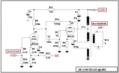
I decided to operate the ECL82 with a B+ of 270V and a OT impedance of close to 8k. The equipment driving the amp will produce up to 2V rms at maximum volume, therefore I did not bypass the cathode resistor of the triode to reduce overall gain. The rectifier is a EZ81. Per datasheet the EZ80 should have worked but required higher PT secondary. PSUDII complained about exeeding the EZ80 maximum ratings. I wanted to play it safe and settled on the EZ81 instead.
I am not new to electronics. Learned the "Radio and Television Technician" trade in Germany after highschool. I worked in the electronic repair business for many years, first in Germany and later in Canada. Nearly a decade ago I switched careers and entered the IT field. Designing and building electronic circuits, be it analog, microcontroller or RF (amateur radio) has always been a passion. But until now I never got around to building with tubes. In my youth I restored a few tube radios (even repaired a few tube TVs) but otherwise only worked with solid state gear. Recent events in my life have brought back memories of the warm sound of tubes, the smell of heated dust and the glow of the tubes. So here I am building a tube amp.
The schematic of the first cut of the design is attached. I'd really appreciate some input as to what I've brewed here, good or bad.
Adi
Initially I wanted to build the EL34 amplifier but I quickly dropped it for a simpler and less expensive idea. With some assistance I picked the ECL82. Initially I thought I'd simply follow someone elses lead but then decided to study the ECL82 datasheet, read some schematics and articles and come up with my "own" design. As much as one could call it that, take the datasheet suggestion and make a few design choices.
I decided to operate the ECL82 with a B+ of 270V and a OT impedance of close to 8k. The equipment driving the amp will produce up to 2V rms at maximum volume, therefore I did not bypass the cathode resistor of the triode to reduce overall gain. The rectifier is a EZ81. Per datasheet the EZ80 should have worked but required higher PT secondary. PSUDII complained about exeeding the EZ80 maximum ratings. I wanted to play it safe and settled on the EZ81 instead.
I am not new to electronics. Learned the "Radio and Television Technician" trade in Germany after highschool. I worked in the electronic repair business for many years, first in Germany and later in Canada. Nearly a decade ago I switched careers and entered the IT field. Designing and building electronic circuits, be it analog, microcontroller or RF (amateur radio) has always been a passion. But until now I never got around to building with tubes. In my youth I restored a few tube radios (even repaired a few tube TVs) but otherwise only worked with solid state gear. Recent events in my life have brought back memories of the warm sound of tubes, the smell of heated dust and the glow of the tubes. So here I am building a tube amp.
The schematic of the first cut of the design is attached. I'd really appreciate some input as to what I've brewed here, good or bad.
Adi
Attachments
I am now laying out the chassis. I understand that to reduce magnetic coupling the OT and PT should be a 90 angle to each other. Looks like it should be possible to get everything arranged on a Hammond 12"X8"X2" or 12"X8"X3" aluminum chassis. I thought about bolting the choke to the rear wall under the PT. I think this should place the choke into the 3rd plane and reduce coupling between it and the other transformers.
Adi
Adi
Attachments
Hi Adi,
regarding magnetic coupling two tips:
1) If you are not restricted to optical symmetry, move the xfrmrs to opposite sides, see my ECL82PSET
2) If you use a steel chassis, magnetic coupling is possible through stray magnetic fields induced in it. Put non-magnetic chims under the iron, so that the iron cores do not touch the chassis, 1-2 mm will do nicely. Alternatively, I use rubber grommets as "bearings" for the screws holding the xfrmrs, which also decouples mechnical hum (a chassis is a resonance corpus).
Good luck with your project!
Tom
P.S.: Regarding EZ81 rectifyers, while they are getting cheaper since they are in current production by JJ/Tesla again, a GZ34/5AR4 still is a robust and easy to get alternative. Needs a separate 5V heater winding, though.
The top of the chassis will be open. It has to look nice but not at the expense of performance. Here is a drawing that places PT on one side and OT on the other. This way there is room for the choke on top. So I substituted the choke with a Hammond enclosed style. Thinking about wiring, it would be a bit awkward.
Does it matter how close the OTs are to each other? What about PT and choke, I would hope that orientation between power transformer and choke wouldn't matter that much.
As far as rectifier is concerned, the GZ34 was already recommended. The Hammond transformer even has a 5V winding I won't be using. I didn't like the idea of mixing sockets and tube styles.
You're in Leverkusen? I just returned from a visit not far from there. Spent most of January in Overath. Grew up in Bensberg and lived in Bergisch Gladbach for a while.
Adi
Attachments
Consider increasing the current through the triode. The ECL82 datasheet only suggests one or to setups. However the triode is infact very similar to the ECC82. An examination of the ECC82 will show you that you can reduce the 220K resistor to 110K and the cathode resistor to 1.1K. This will double the current through it whilst keeping the overall plate voltage. Well worth trying. I did this on my ECL82 preamp and it allowed me to increase the plate to plate feedback I was using.
Talking of plate to plate feedback, I would suggest that you at least try introducing a 160K resistor between the anode of the triode and the anode of the Pentode. This reduces output impedance and will help to linearlise a tube which is not noted for its linearity.
Still the ECL82 sound excellent to my ear.
Shoog
Hello,
I think that is a very good design, especially considering it is your first tube circuit - congratulations!
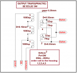
The ECL82 was a good choice. You can expect a very nice sounding amp. I have built a similar amp also using the Hammond 125CSE output transformer and it performs very well indeed with great bass and all. I use the 5000 ohms tap (yellow) but you can experiment with that to suit your speakers.
I would second Shoog's recommendation on increasing the current through the triode. I actually use a load of 100K and a cathode resistance of 255 ohm which works very well, so you might like to experiment in this direction.
I would not agree on the addition of feedback though. While it does make the amp measure much more lineary, it sounds a lot better without. Feedback takes the life out of the amp - you can easily verfy this experimentally.
The aluminium chassis is also a good decision as it does not conduct magnetic radiation. Whether your proposed layout works can als easily be determind: set up the components, connect a pair of headphones to the output transformer, connect a dummy load resistor to the secondary of the mains transformer and apply power. Listen for hum in the headphones and move and rotate the transformers. If there is no hum to be heared it is a good setup.
In the finished amp there will be a small rest of hum because one choke is not sufficient in removing the hum completely but you may be able to live with that. Otherwise you might consider using a second choke which will totally eliminate the hum.
Good luck with the amp!
Best regards
Michael
I think that is a very good design, especially considering it is your first tube circuit - congratulations!
The ECL82 was a good choice. You can expect a very nice sounding amp. I have built a similar amp also using the Hammond 125CSE output transformer and it performs very well indeed with great bass and all. I use the 5000 ohms tap (yellow) but you can experiment with that to suit your speakers.
I would second Shoog's recommendation on increasing the current through the triode. I actually use a load of 100K and a cathode resistance of 255 ohm which works very well, so you might like to experiment in this direction.
I would not agree on the addition of feedback though. While it does make the amp measure much more lineary, it sounds a lot better without. Feedback takes the life out of the amp - you can easily verfy this experimentally.
The aluminium chassis is also a good decision as it does not conduct magnetic radiation. Whether your proposed layout works can als easily be determind: set up the components, connect a pair of headphones to the output transformer, connect a dummy load resistor to the secondary of the mains transformer and apply power. Listen for hum in the headphones and move and rotate the transformers. If there is no hum to be heared it is a good setup.
In the finished amp there will be a small rest of hum because one choke is not sufficient in removing the hum completely but you may be able to live with that. Otherwise you might consider using a second choke which will totally eliminate the hum.
Good luck with the amp!
Best regards
Michael
"You say the triode of the ECL82 compares to the ECC82, but shouldn't it be the ECC81?"
That was off the top of my head - so you could well be correct. I can't remember exactly where I got that information. However my instruction to halve the load resistor and the cathode resistor works ( I have tried it ).
"I would not agree on the addition of feedback though. While it does make the amp measure much more lineary, it sounds a lot better without. Feedback takes the life out of the amp - you can easily verfy this experimentally."
I found that if the partial feedback was overdone then indeed it did rob the end result off life, but 160K proved a good compromise - gaining the benefits of lower output impedance whilst retaining the sound quality. Its so easy to try this that I would recommend an experiement just to see if you like the end result.
If using partial feedback I would also consider going pentode for extra power. The RH84 and RH807 are pentode connected and with plate to plate feedback the sonic effects are marginal according to Alex Kitic the designer.
Alternatively UL if the transformer offers the option. I have just gone from triode to UL on my 807 amp and I like the results more than the triode.
Shoog
The triode section has a max current of 3.5mA and an amplification of 70, with a max plate dissipation of 1 Watt.
So 170V at 0.5mA looks about right to me.
I would also suggest trying some negative feedback. The distortion may get a bit messy in a pentode circuit like this without it. Also it provides more useable power too.
So 170V at 0.5mA looks about right to me.
I would also suggest trying some negative feedback. The distortion may get a bit messy in a pentode circuit like this without it. Also it provides more useable power too.
Oodi,
The schematic makes sense to me. However, there are linearity and damping factor issues.
The linearity of pentode mode is significantly improved when the screen grid B+ value is stable. Zener regulating the screen grid voltage at approx. 150 V. is definitely something to consider.
NFB in 1 form or another is necessary (IMO) to obtain an adequate damping factor with pentodes. The 125CSE's multiplicity of taps can work to your advantage. Think about the "exolinear" topology of Doug Piccard (Bandersnatch). Instead of connecting the triode's load resistor to B+, connect it to a tap on the O/P trafo's primary. You will have to forego the B+ decoupling network, but that is usually OK in a 2 stage circuit.
I calculate that the 220K resistor would drop 110V, leaving 110V on the plate. This would give a dissapation of 110 x 0.0005 = 0.055watts. So theres a good deal of margin to push more current. If going for plate to plate feedback you need more current or the feedback will swamp the triode.
Shoog
Shoog
Thank you for all the input. The great thing is that I can experiment with all of these when the amplifier is put together. No major invasive changes. I've ordered all the parts but some of them will take a few weeks. While I wait I'll be playing with the layout of the components on the chassis and the wiring diagram.
Adi
Adi
I know this is a very old thread, but im looking at building a similar amp, but want to make a 2.1 sound system for my computer, whats the best way to go with this?
Should i add a third channel to the same amp chassis for the sub, or am i better adding a slightly more powerful channel for the sub with a single ended or even push pull pair of el84 tubes? I want to make the system as compact as possible.
Should i add a third channel to the same amp chassis for the sub, or am i better adding a slightly more powerful channel for the sub with a single ended or even push pull pair of el84 tubes? I want to make the system as compact as possible.
OK, well thats interesting to know.
Ive never driven a sub with a valve amp before, but i do see some early motorola amps that had a sub driven with a single ended el84.
I could go harder and use a 6L6 perhaps, but either way, the OP's schematic looks great for computer speakers.
Ive never driven a sub with a valve amp before, but i do see some early motorola amps that had a sub driven with a single ended el84.
I could go harder and use a 6L6 perhaps, but either way, the OP's schematic looks great for computer speakers.
I second radiotron's suggestion: Class D or gainclone amp for the subwoofer + ECL82 SE for the main channels.
Subwoofer amps need only to work with narrow bandwidth but they need to provide strong kicks. Reaching the low frequencies needs a good output transformer and with target power output of around 50W (or more.. depending on your driver), you will spend a lot on this OPT. Not worth it IMO. You won't hear the tubey-ness anyway.
Subwoofer amps need only to work with narrow bandwidth but they need to provide strong kicks. Reaching the low frequencies needs a good output transformer and with target power output of around 50W (or more.. depending on your driver), you will spend a lot on this OPT. Not worth it IMO. You won't hear the tubey-ness anyway.
I probably will end up building a separate sub box with integrated MOSFET amp, but my only problem i find now is what the easiest way is to control the volume of the sub?
Since the sub is on its own seperate channel, i need to find a way to control the volume of the sub at the same time i control the volume level of the speakers.
I could run a cable from the sub to a triple gang pot on the amplifier chassis, but i dont believe this is the done thing?
Either way i will be building a very similar amp to what is discussed here and will post my updates on progress.")
Since the sub is on its own seperate channel, i need to find a way to control the volume of the sub at the same time i control the volume level of the speakers.
I could run a cable from the sub to a triple gang pot on the amplifier chassis, but i dont believe this is the done thing?
Either way i will be building a very similar amp to what is discussed here and will post my updates on progress.
- Status
- This old topic is closed. If you want to reopen this topic, contact a moderator using the "Report Post" button.
- Home
- Amplifiers
- Tubes / Valves
- Building an ECL82 Single Ended Amp ...