Finally i started on my Quadrature Z amp... i will place some pictures of the progress....
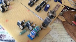
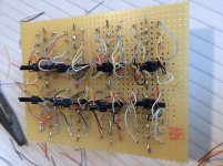
First the driver stage/phase inverter using a EF80 or EF184 in ultra linear mode. With this i will try to drive EL84 output tubes as these are easy driven. Later i will try other tubes depending how the driver performs.
First the driver stage/phase inverter using a EF80 or EF184 in ultra linear mode. With this i will try to drive EL84 output tubes as these are easy driven. Later i will try other tubes depending how the driver performs.
Attachments
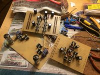
The driver/phase inverter now works fine but it has not enough voltage swing to drive any screen grids. Naturally i could change the ratio of the transformers but then i prefer the old fashioned driver with high dc voltage as changing the ratio also requires higher DC voltages.
This driver stage is perfect as headphone amp (Quadrature Z) or balanced line driver where current is needed.
This driver stage is perfect as headphone amp (Quadrature Z) or balanced line driver where current is needed.
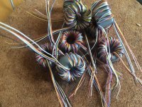
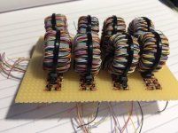
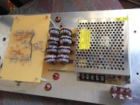
The core material is from a standard PSU common mode choke i found in an electronics dump store. Therefore i am not sure about the exact value. I tested this and found it satisfactory...
Thank you for the links. I was just trying to get rough idea on the core that works for you, I have a few contacts in recycling business selling harvested cores from broken atx supply. I am guessing that 2 pcs of a 33 mm OD would do for an EL34, probably stacked. It will be a very long journey for me so any help and share of experience is greatly appreciated.... Building big Zotls need higher voltages and big Mosfets plus double/parallel impedance converters....
Common mode chokes work best for me but the ferrite transformers used in SMPS power supplies are no good as these work at about 30KHz. Best thing you try with less power first and then crank it up until it starts to distort (not too long otherwise your transistors will fry) , that's how i do it.

![IMG_9844[1].jpg](/community/data/attachments/856/856858-497816b4edc26c99f013eaa7db68b64e.jpg?hash=SXgWtO3CbJ)
![IMG_9845[1].jpg](/community/data/attachments/856/856835-067c0b252c438bc5ec8d1228adc71fc6.jpg?hash=BnwLJSxDi8)
![IMG_9849[1].jpg](/community/data/attachments/857/857468-de4999a13dacaa8fa137d3d846bd4082.jpg?hash=3kmZoT2sqo)
![IMG_9863[1].jpg](/community/data/attachments/859/859077-f8d0f89c6e84a7f1dfc6a5146b95427f.jpg?hash=-ND4nG6Ep_)
![IMG_9861[1].jpg](/community/data/attachments/859/859090-fcfd424f1fd418609611ea4893f7463c.jpg?hash=_P1CTx_UGG)
![IMG_9862[1].jpg](/community/data/attachments/859/859108-4a4b2d8573eed85dbdad76ee0950aa9d.jpg?hash=SksthXPu2F)
![IMG_9856[1].jpg](/community/data/attachments/859/859183-4090984fb1d186887e9b39a5b3947ea5.jpg?hash=QJCYT7HRho)
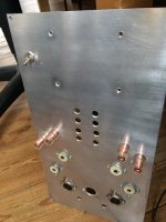
Curious - so you shield the switched valves but keep the normal valves on show?
I need to look into this so I understand it better. I can see from scanning the patent.. Almost no point doing an SMPS booster if the amp is the booster 😉
It basically looks like a current chopper controlled by the valve stage using magnetics DC current. The switching is by SMPS PWM, that creates a square wave AC and the magnetics flux is controlled by the DC for the output for that 1/2 of the wave.
Last edited:
The simple way to look at the Berning type switch-mode OTs is that it is just a square wave (FERRITE HF) DC to DC converter. The tube is put across the HV output side and whatever current it draws shows up as a higher current on the LV side of the converter. You just use the LV terminals like it is a high current linear device then.
Any type of DC to DC converter will work, providing it has sufficient bandwidth.
For example, one could just use a capacitive ladder type (multi-step) voltage multiplier with the tube across the HV side. Higher switching frequency needed to compensate for the multi step process, but no leakage L to contend with. The capacitors can be very small at HF, less than the distributed C in a conventional OT. You actually want a triangle wave HF with the caps to limit (flat level, to audio) the HF current pulses.
The Berning type scheme typically has the LV sides for the two tubes configured as a stacked totem pole, like a typical SS amp. It is also possible to combine each converter with its LV power supply and configure them like a Circlotron. Whether you get CFB effects however depends on the tube referencing, which is normally isolated from the load by the converter xfmr.
Last edited:
The simple way to look at the Berning type switch-mode OTs is that it is just a square wave (FERRITE HF) DC to DC converter. The tube is put across the HV output side and whatever current it draws shows up as a higher current on the LV side of the converter. You just use the LV terminals like it is a high current linear device then.
Any type of DC to DC converter will work, providing it has sufficient bandwidth.
For example, one could just use a capacitive ladder type (multi-step) voltage multiplier with the tube across the HV side. Higher switching frequency needed to compensate for the multi step process, but no leakage L to contend with. The capacitors can be very small at HF, less than the distributed C in a conventional OT. You actually want a triangle wave HF with the caps to limit (flat level, to audio) the HF current pulses.
The switching booster (LT1243 based) I am working on used an RC network for the timing at 95KHz currently, so this is not so far away, I'll have a look at building a sim tonight. Should prove interesting. I'd look to replace the back end 2x4 PP ecc99 stage - the front end is an M60-inspired differential amp. A maida-LT3080 regulator would provide regulation on that front end from the same switching.
I'd look to replace the back end 2x4 PP ecc99 stage
You still need the tubes with the Berning type converter to act as the linear HV series control devices.
I suppose a 50% duty cycle boost converter could work also in place of the square wave inverter (minimal ripple), but those look like current sources without some N Fdbk to bring them back to V sources. They usually lack isolation too, which is important for tube grid/cathode V referencing.
The Cuk converter along with other related ripple free converters could work well too, but all of them look like current sources without some N Fdbk.
Last edited:
You still need the tubes with the Berning type converter to act as the linear HV series control devices.
I suppose a 50% duty cycle boost converter could work also in place of the square wave inverter (minimal ripple), but those look like current sources without some N Fdbk to bring them back to V sources. They usually lack isolation too, which is important for tube grid/cathode V referencing.
The Cuk converter along with other related ripple free converters could work well too, but all of them look like current sources without some N Fdbk.
My booster design uses a 300W 240Vac->48Vdc isolated mean well SMPS (mains safety for transients, active power correction, and the usual over/under and thermal protection). The design seems able to put out 150W for 180W input at 230V. It could do more but that's all I need.
I had it in my head that I can just use a single pair of ecc99 to control the HV side that simplifies things a little. Leaving the ZOTL to control the current.
Zotl just acts like an xfmr. Reducing the tubes will mean a higher impedance ratio needed to handle the same current. The single tube will have to handle higher V (and power diss). [ Zotl does not provide power gain by itself }
Understood - just been looking into options for controlling the half bridge. A overly complicated way the LT3723 series, a synchronous push pull IC, can be setup Half bridge and has the added benefit of current limiting, duty cycle control along with startup etc: https://www.analog.com/media/en/technical-documentation/data-sheets/372312f.pdf
I did look at this chip before with the SMPS and running it to drive alternating boosters.
I have 15 minutes left of 'geek time'.. I'll read the patent properly.
I did look at this chip before with the SMPS and running it to drive alternating boosters.
I have 15 minutes left of 'geek time'.. I'll read the patent properly.
- Home
- Amplifiers
- Tubes / Valves
- ZOTL and ferrites