I suggest you to arrange an excel file, especially if you want to play with simulations, because it saves you alot of time.
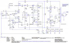
Good suggestion. Schematic below including the Toroidy EL84 OPT. 404H primary with 43% taps gives Lp of 32.82H and Ls of 18.68H.
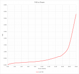
I also have an Excel macro that parses the LTSpice error log and pulls out power and THD information. Plot of THD vs power also below.
THD @ 1W is 0.11%. Less than 1% up to about 17W. 3.9% at 20W.
It'll be interesting to see how the actual measurements compare.
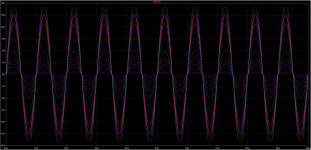
I couldn't resist including the LTSpice waveform plot because it's pretty.
Attachments
Great job! May I ask you to upload the Excel Macro? Would it be possible to adjust it in order to separate each harmonic, in order to see how it performs?
Here you go. Let me know if you have any problems. I can always zip up the spreadsheet.
Attachments
There is a new, ongoing group buy for BH EL34 PCBs and the complementary PSU.
See here:
https://www.diyaudio.com/forums/group-buys/368190-gb-el34-baby-huey-amp-psu-mk2-pcb.html#post6547232
ECL86 PCBs had been scarce.
Good luck.
See here:
https://www.diyaudio.com/forums/group-buys/368190-gb-el34-baby-huey-amp-psu-mk2-pcb.html#post6547232
ECL86 PCBs had been scarce.
Good luck.
Schematic below including the Toroidy EL84 OPT. 404H primary with 43% taps gives Lp of 32.82H and Ls of 18.68H.
I’m enjoying learning about your (and Zintolo’s) simulations of BHEL34 and I’m trying to learn LTSpice myself to be able to do this “magic”.
Could you point me to a reference where I could learn more about output transformer modeling in LTSpice and the calculations of inductance you performed.
I noticed in the schematic that while both of you have 0.6 mA through each triode, you are using one red and one blue LED in the CCS, and Zintolo two reds, with different values of R16. Does that not have any significant influence on the triode currents? Additionally, I thought the purpose of the “two LED” modification was to achieve a 1 mA current.
Hello François,
Thanks for your help François.
By the way, there are plenty of new ECL86 on ebay and the prices are not so hot. Have a look if you are interested.
About LT Spice, https://web.mit.edu/6.101/www/s2020/handouts/LTSpiceIntro.pdf.
http://dept.me.umn.edu/labs/hmd/lab/docs/LTspice_Guide.pdf
If you read French (?) there is a big book : Amazon.fr
About transformer, there are divert macro in LT Spice you can combine, perfect transformer at the begining is well enough to understand what is happening;
Could you point me to a reference where I could learn more about output transformer modeling in LTSpice and the calculations of inductance you performed.
I noticed in the schematic that while both of you have 0.6 mA through each triode, you are using one red and one blue LED in the CCS, and Zintolo two reds, with different values of R16. Does that not have any significant influence on the triode currents? Additionally, I thought the purpose of the “two LED” modification was to achieve a 1 mA current.
Hi Francois. I can't point you to a single reference for transformers. I've built up what I know over the years through online searches, downloading and playing with models people post and questions to diyAudio like this rather spirited thread: LTSpice model for a commercial toroidal output transformer.
While not specifically transformer-related, if you haven't done all the tutorials in mooly's great thead I highly recommend it: Installing and using LTspice IV (now including LTXVII). From beginner to advanced.
As for the CCS 0.5mA for each triode was the recommendation for a total of 1mA through the CCS. It was discussed in posts #2420 and #2421.
dch53,
Thanks for the pointers and encouragement. I will study the thread LTSpice model for a commercial toroidal output transformer That is exactly what I was looking for.
Thanks also for reminding me about Zintolo’s handy table in post #2421. I had remembered incorrectly that the 2 mA was the current through the two cathodes, rather than through the LEDs.
Last edited:
Here you go. Let me know if you have any problems. I can always zip up the spreadsheet.
Thank you very much dch53!
The right current for the two triodes is between 0.6 (for EL84) and 0.7 mA (for EL34), see here: EL84 Amp - Baby HueyAs for the CCS 0.5mA for each triode was the recommendation for a total of 1mA through the CCS.
question about global feedback -- does installing R1 in the PCB have any effect if the OPT secondary is connected directly to the binding posts and not through the feedback terminals on the PCB?
Does anyone know the answer to this?
Thanks
Does anyone know the answer to this?
Thanks
Itsik,
I believe you are asking if it will have an effect on the performance of the amp if you install the feedback R1 resistor on the PCB, but NOT connect it to the output transformer secondary. It will not.
I have been making slow progress and finally tested one channel last night - came up perfectly, a tribute to an excellent design
a few pictures for this thread
Putting the horse before the cart - playing with layout options before all the parts had arrived

I decided to go with the solid state power supply as buying a another transformer to accommodate the tubed regulator didn't seem the most sensible thing to do . The one thing I need to look into is the timer - it takes about 2 minutes to release. I seem to recall that it is just a capacitor value change.
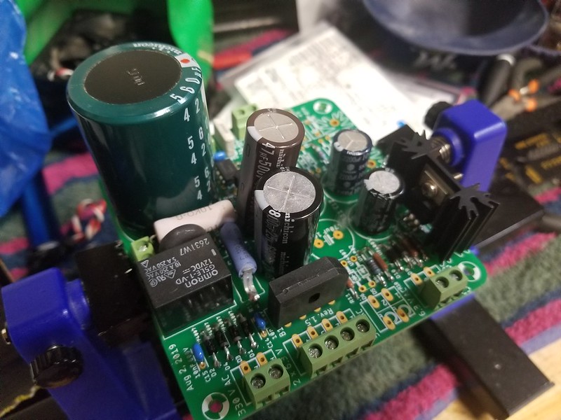
Assembled and ready to be tested

and finally found some time to test one of the boards

The most challenging thing about about building this amp has been the inability to just sit down and build it
..dB
a few pictures for this thread
Putting the horse before the cart - playing with layout options before all the parts had arrived
I decided to go with the solid state power supply as buying a another transformer to accommodate the tubed regulator didn't seem the most sensible thing to do . The one thing I need to look into is the timer - it takes about 2 minutes to release. I seem to recall that it is just a capacitor value change.
Assembled and ready to be tested
and finally found some time to test one of the boards
The most challenging thing about about building this amp has been the inability to just sit down and build it
..dB
I am having difficulty zeroing out the anode voltages on the second build - I can adjust from 25 to 37 V . I could increased the resistor size but something tells me that is not the correct solution. I made sure everything is soldered correctly and I can adjust the bias for the power tubes without any trouble.
I have the led mod for R15 and the negative bias from my bias transformer is -80V ( I have used a 37K resistor per the table.
any ideas as to how to troubleshoot are welcomed.
..dB
I have the led mod for R15 and the negative bias from my bias transformer is -80V ( I have used a 37K resistor per the table.
any ideas as to how to troubleshoot are welcomed.
..dB
I checked everything that could make sense I reduced the bias supply to 40V, measured the bias for the 12AX7 to be 2.3mA. Switched ru ES on the off chance it was a tube and nothing changes this odd behavior. I ultimately dropped a 5K trimmer into the circuit and could null the voltage.
Any ideas as to where to look for a possible problem or if this is OK to use the amp like this.
It seems to be working normally otherwise
Thanks.. dB
Any ideas as to where to look for a possible problem or if this is OK to use the amp like this.
It seems to be working normally otherwise
Thanks.. dB
- Home
- Amplifiers
- Tubes / Valves
- EL84 Amp - Baby Huey