@JKeny: At ETF there's no "national-grouping" as such. It's one community.
Sometimes the same nations gather in a car to go to ETF or in a room to do demos.
I'd say this is more related to the language barrier than to anything else.
English is the universal language at the ETF but not everyone's mothertongue,
so the behaviour is quite understandable. At the end of ETF, everyone will have listened to everyone's system. Besides, every european football-nation will have made fun of their favorite foreign opponent and vice-versa. And the end
they all have some beers & drinks and are happy to be at ETF.
@adamus: The enormus heatsinks were a 100% fit to cover the open sides
of my U-shaped chassis without any additional tooling.
Besides some (small) heatsinks were needed anyhow for the CCS.
As I had the heatsinks in my scrapbox, their putting into use was a no-brainer.
@YvesM: I'm planning a "serious" 2-way open-baffle system (from Martin J.King) which is transportable without too much hassle and can cope with
larger rooms. If i've something presentable for next ETF10, we should
cooperate (as we did for the wine) .
.
Bye
Yves
PS: According to my wife, the size of my "equipment" (so to speak) at home is by far too large .
Sometimes the same nations gather in a car to go to ETF or in a room to do demos.
I'd say this is more related to the language barrier than to anything else.
English is the universal language at the ETF but not everyone's mothertongue,
so the behaviour is quite understandable. At the end of ETF, everyone will have listened to everyone's system. Besides, every european football-nation will have made fun of their favorite foreign opponent and vice-versa. And the end
they all have some beers & drinks and are happy to be at ETF.
@adamus: The enormus heatsinks were a 100% fit to cover the open sides
of my U-shaped chassis without any additional tooling.
Besides some (small) heatsinks were needed anyhow for the CCS.
As I had the heatsinks in my scrapbox, their putting into use was a no-brainer.
@YvesM: I'm planning a "serious" 2-way open-baffle system (from Martin J.King) which is transportable without too much hassle and can cope with
larger rooms. If i've something presentable for next ETF10, we should
cooperate (as we did for the wine)
.Bye
Yves
PS: According to my wife, the size of my "equipment" (so to speak) at home is by far too large .
Last edited:
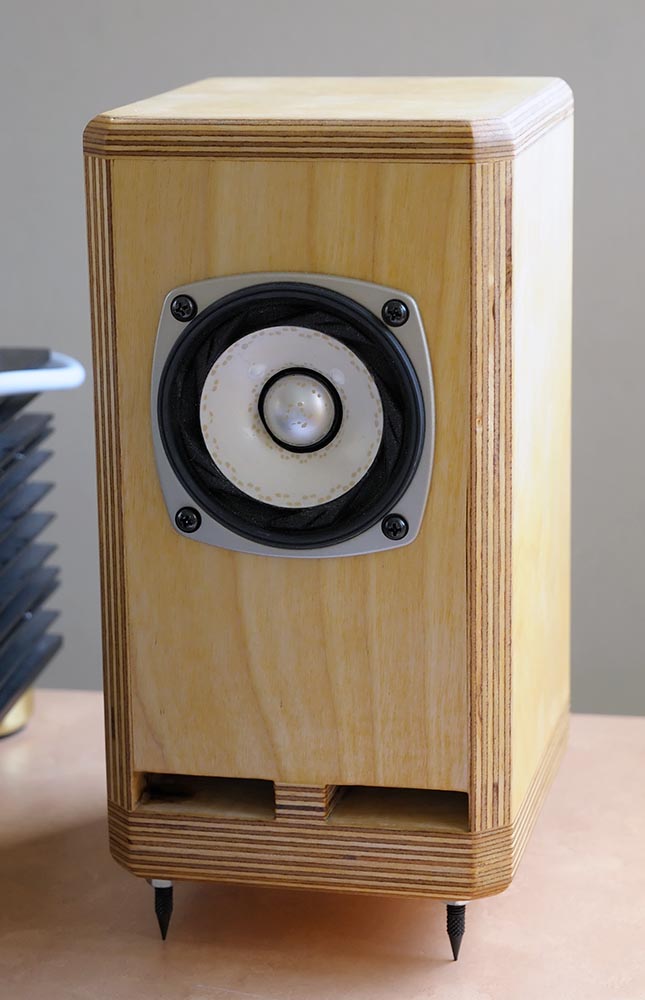
Yves Dupont's Baby Huey has been spotted at the ETF 2009.
There is a set of uFonken in that picture too (and Henkjan's desktop TLs)... the picture is small, but there is a hint that the FF85 are EnABLed. Yves, who's are those?
dave
Dave you caught me. I admit building the uFonken without dropping you a note (mea culpa  )
)
You correctly spotted Henkjan's DeskTop TL which i built too.
Christian Gather made a very nice closeup of the EnABLed uFonken:
They both work great. I didn't do any measurement so far, the DeskTop TL with
the Alpair5 seems to go a bit lower in the bass but can not play as loud as the
uFonken with the FF85k. Enabling the FF85k was accompanied with lots of
cursing. The driver is too small to get my fingers around it while painting
the EnABL patterns. The bigger FE103S was a piece of cake in comparison.
So far I didn't make my mind up which one to take to my office as a desktop
system. After the Alpair5 is broken in, i'll do some more comparisons.
The BabyHuey's preferred mate seems to be the uFonken.
A tube amp will usually benefit if you correct the impedance dips/peaks
of the speaker an present an even impedance to the amp. When I'll be fiddling
around with the ARTA measuring software, I'll check if an impedance
correction actually helps the tube amp. But i doubt if the effect will be
very audible.
My second set of FF85k will go into an open baffle (Martin J.King style) together with an Eminence Alpha 15A. I'll pick up the birch-ply this week.
A thing i wanted to say for a long time: Thanks Dave for providing the diy-community with plans for the Fonken line and for the new EL70/Alpair enclosures. Your effort is greatly appreciated.
-Yves
)You correctly spotted Henkjan's DeskTop TL which i built too.
Christian Gather made a very nice closeup of the EnABLed uFonken:
They both work great. I didn't do any measurement so far, the DeskTop TL with
the Alpair5 seems to go a bit lower in the bass but can not play as loud as the
uFonken with the FF85k. Enabling the FF85k was accompanied with lots of
cursing. The driver is too small to get my fingers around it while painting
the EnABL patterns. The bigger FE103S was a piece of cake in comparison.
So far I didn't make my mind up which one to take to my office as a desktop
system. After the Alpair5 is broken in, i'll do some more comparisons.
The BabyHuey's preferred mate seems to be the uFonken.
A tube amp will usually benefit if you correct the impedance dips/peaks
of the speaker an present an even impedance to the amp. When I'll be fiddling
around with the ARTA measuring software, I'll check if an impedance
correction actually helps the tube amp. But i doubt if the effect will be
very audible.
My second set of FF85k will go into an open baffle (Martin J.King style) together with an Eminence Alpha 15A. I'll pick up the birch-ply this week.
A thing i wanted to say for a long time: Thanks Dave for providing the diy-community with plans for the Fonken line and for the new EL70/Alpair enclosures. Your effort is greatly appreciated.
-Yves
Dave you caught me. I admit building the uFonken without dropping you a note
It isn't mandatory
I do like seeing people's efforts thou, Very nice use of the plywood edge-grain.A tube amp will usually benefit if you correct the impedance dips/peaks of the speaker an present an even impedance to the amp.
Not much in that for the FF85
My second set of FF85k will go into an open baffle (Martin J.King style) together with an Eminence Alpha 15A. I'll pick up the birch-ply this week.
We've got one of those in the queue too. I need to make some more drivers thou. The ones for the OB are in the proto uFonken^2
A thing i wanted to say for a long time: Thanks Dave for providing the diy-community with plans for the Fonken line and for the new EL70/Alpair enclosures. Your effort is greatly appreciated.
dave
Hi All Baby Huey or PP el84 fans out there. As you might know I'm busy with my Baby Huey build. I have the output transformers for them already. But I've already started thinking which transformers I'm going to get to compare and see if I can get my BH to the next level.
So as I wondered over at the Magnequest site. I saw a thread coming up on the MQ 565. (For which Mike has actually got/bought the blueprints). And the option of nickel pinstripes.
So if you are in the market for something like this...
Announcement
And a happy owner
MQ 565 fan...
No affiliation. Just a big MQ fan.
Two more endorsements:
I'll throw in another "Hell Yeah, these rock" on the MQ 565. I have a pair of these in nickel pinstripe/m4, used in an ST-35 (the Shannon Parks design, diytube.com, with some modifications...), it just doesn't get any better than these trannies for EL84 usage, IMNSHO.
-Ed
Ed Sawyer's post
I can attest that the 565's are awesome PP EL84 OTs.
Words like devastating, amazing, and damn come to mind.
If you do a run, let me know, I only have one pair left
and they are accounted for already for a future build.
Again, highly recommended. Love em.
Triode3's post
What is the minimum current requirement of the -48v rail?
Reason I ask is that I have a transformer which suits building a stereo BH, other than the negative rail. I have a 70v@40mA bias winding spare, which would be fine for just the bias but I'm unsure if it is suitable for the negative rail.
Thanks.
Reason I ask is that I have a transformer which suits building a stereo BH, other than the negative rail. I have a 70v@40mA bias winding spare, which would be fine for just the bias but I'm unsure if it is suitable for the negative rail.
Thanks.
The minimum current requirement is:
1mA for front end diff amp
about 2 to 3 mA for each of the 2 source followers driving the output tube grids
So say about 7mA per channel or 14mA for 2 channels.
The bias tap will handle that easily.
Also the -48V is not that critical as to the actual voltage. For source followers direct coupled to the output tube grids like in the fixed bias BH circuit the signal at the MOSFET source pin will sit at the required bias volts (about -12V for EL84), will swing up to 0V and down to at least -24V ( 2 x the bias volts), accordingly the "rule of thumb" for that -ve rail is that it should be a minimum of about 3 times the bias volt, that is more than -36V. There is no real upper limit but you start wasting power and generating a lot of heat if you go too high and the current sources need to use higher voltage rating transistors. -48V is an ideal value. Check back on what transistors I recommended for the source follower CCS loads. I think I suggested 2N5551, if so they are 160V rated and so you wouldn't want to get too close to that. With a 70V winding and a bridge rectifier you are likely to end up at around -85 to -90 volts. Check what transistors you are using in the diff amp and source follower current sources but if using the 2N5551 there will be no problem with that rail.
Cheers,
Ian
Last edited:
News Coming - I have been running the Original Prototype for a couple of months on the HiFi System and had concluded that something was not quite right yet sonically. It is great but falls just short of totally gorgeous.
I have theorised that the problem may be with time shift due to Output Tranny leakage inductance which will mess with the balanced shunt feedback at higher fequencies BUT also messes with the time of the Ultralinear feedback.
This prototype DELIBERATELY had Hammond 1608 Output Trannies put back into it.
I started adding Zobel Networks across the speaker (Secondary of output tranny) but was never 100% satisfied.
I then started adding zobel networks between the anode and Ultralinear taps of the output tranny. I first tried
1) 1K + 820pF - Hummm.. a bit better
2) 1K +1500pF - Better again
3) 1K + 2n2 - Verge of drop dead gorgeous
Then looking at the reflected impedance between the anode and ultralinear taps of a 8K Raa Output Tranny I calculated an impedance of 320 Ohms.
Maybe that 1K is too high.
So tried
5) 560 Ohms + 4n4 (2 off 2n2 in parallel) - Damn, now we are really getting somewhere. Maybe a bit overdone but I think better than 1K + 2n2
Time to stop screwing about and do this scientifically - So in the next week or so I will be doing Phase and amplitude plots to set the zobels exactly for flattest phase and frequency response I can manage.
I can tell you the addition of these zobels shows up in crispness, stereo image, stereo balance and particularly in amplifier pace. It also seems to reveal more fine detail.
I'm not actually surprised - in an earlier post I noted that in Fritz Langford-Smiths articles on Ultralinear he stated that capacitors (or zobels) were required between the anode an screen taps and then for the next 40+ years people built Ultralinear Amps without them.
The other thing which is of passing interest - when I ran a frequency response on this amp, way back when, I recall noting that there was a resonance at about 68KHz from the output tranny.
1K + 2n2 is 72kHz
560 Ohms + 4n4 is 64.5kHz
Cheers,
Ian
Cheers,
Ian
I built some Baby Huey modules recently (fixed bias schematic), the module with all the caps is an attempt to get +/-50V from a 50V bias winding, none of the modules are tested yet. I'm going to try them with 6P3S (6L6G) first, if no luck I'll try EH 6V6. I'm a bit worried about the B+ being a bit high for the 6P3S screen grids (B+ will be 360V). But I do have an EL84 amp which has the correct voltages waiting for a rebuild if the first project doesn't work out. Looking forward to it, can't wait. Thanks for the update on Zobels on the OPT's Ian. Wondering if that might have been the "missing link" for UL that was never really missing in the first place...anything is possible...
Ian.
Ian.
News Coming - I have been running the Original Prototype for a couple of months on the HiFi System and had concluded that something was not quite right yet sonically. It is great but falls just short of totally gorgeous.
I have theorised that the problem may be with time shift due to Output Tranny leakage inductance which will mess with the balanced shunt feedback at higher fequencies BUT also messes with the time of the Ultralinear feedback.
This prototype DELIBERATELY had Hammond 1608 Output Trannies put back into it.
I started adding Zobel Networks across the speaker (Secondary of output tranny) but was never 100% satisfied.
I then started adding zobel networks between the anode and Ultralinear taps of the output tranny. I first tried
1) 1K + 820pF - Hummm.. a bit better
2) 1K +1500pF - Better again
3) 1K + 2n2 - Verge of drop dead gorgeous
Then looking at the reflected impedance between the anode and ultralinear taps of a 8K Raa Output Tranny I calculated an impedance of 320 Ohms.
Maybe that 1K is too high.
So tried
5) 560 Ohms + 4n4 (2 off 2n2 in parallel) - Damn, now we are really getting somewhere. Maybe a bit overdone but I think better than 1K + 2n2
Time to stop screwing about and do this scientifically - So in the next week or so I will be doing Phase and amplitude plots to set the zobels exactly for flattest phase and frequency response I can manage.
I can tell you the addition of these zobels shows up in crispness, stereo image, stereo balance and particularly in amplifier pace. It also seems to reveal more fine detail.
I'm not actually surprised - in an earlier post I noted that in Fritz Langford-Smiths articles on Ultralinear he stated that capacitors (or zobels) were required between the anode an screen taps and then for the next 40+ years people built Ultralinear Amps without them.
The other thing which is of passing interest - when I ran a frequency response on this amp, way back when, I recall noting that there was a resonance at about 68KHz from the output tranny.
1K + 2n2 is 72kHz
560 Ohms + 4n4 is 64.5kHz
Cheers,
Ian
Cheers,
Ian
keep us posted ian, I am interested in trying this.
Time to stop screwing about and do this scientifically - So in the next week or so I will be doing Phase and amplitude plots to set the zobels exactly for flattest phase and frequency response I can manage.
Good luck Ian, hoping you can generalize from what you learn to include non-1608 ot's
Brgds Bill
Anyone spot the "deliberate" ..cough ..cough mistake above.
For Raa of 8K the reflected impedance between anode and screen taps is not 320 Ohms.
It is (0.3)^2 x 8K = 720 Ohms
Last night I changed that zobels from 560R + 2n2 to 710 + 2n2 by adding 150 Ohms to each of the existing zobels.
I thought that was a step in the right direction. Tested by applying shorting links across the added 150 Ohms an then cutting the links with (INSULATED) cutters. BUT I'm inclined to think (based upon that 720 Ohms calculation above) that the original 1K value for the zobel resistors is abut right.
Cheers,
Ian
Cheers,
Ian
PT
Greetings All:
Ian, this is a fantastic thread. I am new to the forum and so only made it to about post 210 before may head began to ache too much. I have an old Harman Kardon A250 Epic chassis with a dead OT that may become a Baby Huey with a line level pre and some baxandall tone controls.
Perhaps offensively off topic, if so, mod please delete!
I have available 5 or 6 custom PT wound for me for a run of guitar amps. (I have 8 left but want to keep a couple for this project and one other) I am dissatisfied with the secondary HT winding and need to sell these at cost. They are 235-0-235 at 200ma with 120VAC in (Sorry OZ) but I have run them at full roar guitar distortion at 60 watts out with no ill effect. Phil Heyboer said 200ma plus. M6 iron.
Problem is, they have only one 4 amp 12VAC filament winding with no center tap. I had intended them for 7551s and they are ideal for that. Most folks though are unwilling to run a guitar amp with an out of production somewhat rare tube. I have used them for EL-84 and use series filaments on the output tubes and and use the pre tubes wired to 4&5. They make about 320VDC idle with EL-84 biased at 70% and a stealth diode package.
Cost less shipping for me was $54.50. That's what I'll sell them for +shipping to you if they will work. We need to add an additional 5 or 6 VAC trafo under the chassis for the doubler circuit. It doesn't need to be very big does it.
I hope you folks don't mind me jumping in here with this but many have complained of the unavailability of a proper HT winding and as I say, I'm selling at a shipping loss so it's not quite a commercial venture. Besides, it may not work for you with the 12VAC winding. I always put in a 100ohm hum balance pot.
Wait a minute, would Baby Huey work for 7551? The tube will last a couple of human lifetimes in stationary use......they bias more in the 18V range though so might be more 6V6 like. It is also a beam PT not a pentode. Hmmmm. Never mind
By the way, has the 6V6 version evolved past the scheme on page 3 or so? I intend to read all 900 posts, but it sure would be nicer in book form. Or with your thinking points canonized into a single synopsis.
- Home
- Amplifiers
- Tubes / Valves
- EL84 Amp - Baby Huey