Hey!
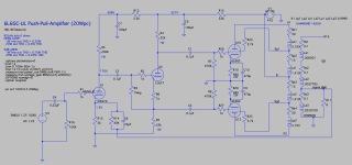
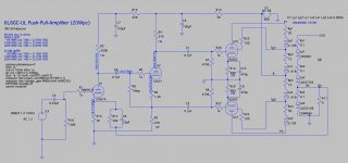
It's been a while, but I've been noodling on a design for a 20W PP amp and decided to take a whack at a 6L6GC UL PP. Not sure that it's all it could be, but I wanted to keep it simple.
I have attached the schematic in progress, but should mention that the driver circuit is from the EL84PPP in this post and seems to be fine to supply voltage gain for the 6L6s.
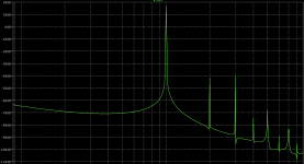
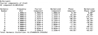
LTSpice is indicating about .17% THD with 6dB of global NFB at 10W with about 20W of power available before clipping. 2H / 3H are about -58dB down at 10W / 1kHz.
Thoughts from the community would be much appreciated.
Kofi
It's been a while, but I've been noodling on a design for a 20W PP amp and decided to take a whack at a 6L6GC UL PP. Not sure that it's all it could be, but I wanted to keep it simple.
I have attached the schematic in progress, but should mention that the driver circuit is from the EL84PPP in this post and seems to be fine to supply voltage gain for the 6L6s.
LTSpice is indicating about .17% THD with 6dB of global NFB at 10W with about 20W of power available before clipping. 2H / 3H are about -58dB down at 10W / 1kHz.
Thoughts from the community would be much appreciated.
Kofi
Attachments
With Ohms' law I find some discrepancies in the current in the first stage when using the values as stated in the schematic.
- R13 and R14 paralleled give a cathode resistance of 1875 Ohm. So the cathode current would be V/R = 1.5/1875 = 0.8 mA.
- The current through anode resistor R13 would be V/R = 136/200K = 0,68 mA.
- The current through R12 would have to be V/R = 15/2K2 = 6.81 mA.
Probably the value for R12 is 22K instead of 2K2. But that doesn't explain the difference between the calculated anode and cathode current.
Cool!
I've noodled around with a design similar to that. 12AX7 input/voltage amp, 12AT7 (or 12AU7) split-load phase inverter, PP 6L6. I actually built one with the 6L6s in triode, but had to give up because of a mysterious hum problem most likely caused by the weird power transformer I used (I'm going to try to give it another shot at some future date).
One comment:
It might be better to make R15 = 2.2k and R12 = 22k (instead of the other way around).
Since R15 will have the combined current of both U1 (12AX7) and U2 (12AT7), you won't see as much of a voltage drop there if it's 2.2k, allowing U2 to work with higher voltages, for more possible voltage swing. Probably a good idea for a phase splitter/driver stage.
U1, being a high rp/high mu triode, will be susceptible to low frequency problems if its plate supply feed is not decoupled fully down to extremely close to DC. Also, since its Ip is going to be <1mA, 22k won't drop many volts (~20V?), so there should still be enough voltage swing possible from U1, even if its plate voltage is a tiny bit lower.
Otherwise, best of luck with this! I think this simple topology may work out really well.
Last edited:
Sorry for the delay in responding-- work has been busy.
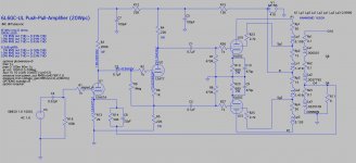
You're right, PFL200. I kept some hard-coded voltages on the schematic from a prior iteration. I added the corrected values here (new values were calculated by LTSpice).
Thanks for the advice, rongon. I tried to get the first dropper resistor down to 2.2K, but the B+ is 410 and it wasn't enough to drop the plate voltage on the 12AT7 to below 300 (max voltage @ plate, per the datasheet). I am at max plate voltage with a 12K dropper.
Any other comments? Also, a question about the screen resistors for the 6L6s. Any reason I can't use 2K7 here? I've seen screen resistor values of 100R elsewhere and didn't know why.
Thanks!
Kofi
With Ohms' law I find some discrepancies in the current in the first stage when using the values as stated in the schematic.
You're right, PFL200. I kept some hard-coded voltages on the schematic from a prior iteration. I added the corrected values here (new values were calculated by LTSpice).
It might be better to make R15 = 2.2k and R12 = 22k (instead of the other way around).
Thanks for the advice, rongon. I tried to get the first dropper resistor down to 2.2K, but the B+ is 410 and it wasn't enough to drop the plate voltage on the 12AT7 to below 300 (max voltage @ plate, per the datasheet). I am at max plate voltage with a 12K dropper.
Any other comments? Also, a question about the screen resistors for the 6L6s. Any reason I can't use 2K7 here? I've seen screen resistor values of 100R elsewhere and didn't know why.
Thanks!
Kofi
Attachments
I tried to get the first dropper resistor down to 2.2K, but the B+ is 410 and it wasn't enough to drop the plate voltage on the 12AT7 to below 300 (max voltage @ plate, per the datasheet).
Is that 'max B+' is 300V or is that max 'plate voltage' (meaning plate-to-cathode) is 300V?
Looking at the data sheet, it looks to me like they mean plate-to-cathode voltage, not a maximum B+.
The way you have it now, the plate-cathode voltage on U2 is about 220V.
You can also increase the value of R4 and R5 as needed. 27k 1W would work. Actually 33k 1W would also work, depending on the B+ voltage and plate-cathode voltage desired.
The advantage of larger value R4 and R5 would be a flatter load line for U2 (12AT7) meaning lower THD. However, you do want to keep the 12AT7 plate current >/=3mA, and its grid bias at -1.7V or more negative. It's all a balancing act.
Would you be willing to post the .asc file? I'd like to play around with it a bit, to see if what I'm saying isn't completely off the mark.
Edit to add:
The heater to cathode voltage on the 12AT7 will be important. You want that to stay below about 80V. If you raise the B+ voltage to the 12AT7, the 12AT7 cathode may end up higher than +100V, and you would then need to float the heater voltage above ground, maybe up to +50V or +60V.
--
Last edited:
question about the screen resistors for the 6L6s. Any reason I can't use 2K7 here?
Resistance in series with the screen grid will introduce some degeneration (increased g2 internal resistance, reduction of gain). You actually don't want to introduce degeneration there, because it will degrade performance. However, you also want to make sure there's no transient oscillation on signal peaks, so you want a screen stopper there. You want the screen stopper to be large enough in value to suppress oscillation, but not so large as to introduce too much degeneration. Yet another balancing act.
MerlinB explains the screen stopper in UL stages on his Valve Wizard site:
The Valve Wizard
Some guitar amp guys go for 'screen compression' from using high value screen stoppers.
Grid stopper resistors and screen resistors...clarification
Screen resistors, on the other hand, are handy for eating up excess screen current when the plate voltage is peaking. If the Rg2 is un-bypassed (as most screen grid resistors are) then the larger the Rg2 resistance, the more compression you will end up with in the g1 curves. (i.e. more compression = decreased transconductance). Having said that, a Rg2 value of 470R to 1k on your typical 6V6 or 6L6 screen won't have much impact on compression, but 100k will compress it heaps.
I'd say for the screen stopper in your UL configuation, I'd put in 100R and see how it goes. Increase to 470R if you need to. I'm not sure what 2.7k would do, but it may be high enough R to introduce some degeneration (lowering gm of the 6L6 a bit).
Is that 'max B+' is 300V or is that max 'plate voltage' (meaning plate-to-cathode) is 300V?
Looking at the data sheet, it looks to me like they mean plate-to-cathode voltage, not a maximum B+.
The way you have it now, the plate-cathode voltage on U2 is about 220V.
You can also increase the value of R4 and R5 as needed. 27k 1W would work. Actually 33k 1W would also work, depending on the B+ voltage and plate-cathode voltage desired.
The advantage of larger value R4 and R5 would be a flatter load line for U2 (12AT7) meaning lower THD. However, you do want to keep the 12AT7 plate current >/=3mA, and its grid bias at -1.7V or more negative. It's all a balancing act.
Would you be willing to post the .asc file? I'd like to play around with it a bit, to see if what I'm saying isn't completely off the mark.
Edit to add:
The heater to cathode voltage on the 12AT7 will be important. You want that to stay below about 80V. If you raise the B+ voltage to the 12AT7, the 12AT7 cathode may end up higher than +100V, and you would then need to float the heater voltage above ground, maybe up to +50V or +60V.
--
Thanks!
I attached the latest edits to the schematic (screen shot and .asc file). I dropped the B+ to 400V, changed the dropper resistor to 5K and upped R4 and R5 to 27K. This results in about 300V at the plate ~2.5V of bias voltage and 80V at the cathode, which is under the max heater to cathode voltage.
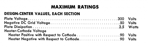
Also, I attached a screen shot ot the 12AT7 datasheet I have been using for reference. It looked to me like the 300V was just the plate maximum to 0V, not to cathode. Am I understanding this incorrectly?
I'd say for the screen stopper in your UL configuation, I'd put in 100R and see how it goes. Increase to 470R if you need to. I'm not sure what 2.7k would do, but it may be high enough R to introduce some degeneration (lowering gm of the 6L6 a bit).
Makes sense! So, I did reduce the screen resistors to 100R as well. Interestingly enough, LTSpice is calculating an increase in THD resulting from this. I am guessing this is because Spice sees this as a decrease in localized NFB. Looks like the calculated distortion figures may not be infallible.
Please feel free to tinker with the schematic as you see fit.
Thanks again.
Kofi
Attachments
Thanks!
I attached the latest edits to the schematic (screen shot and .asc file). I dropped the B+ to 400V, changed the dropper resistor to 5K and upped R4 and R5 to 27K. This results in about 300V at the plate ~2.5V of bias voltage and 80V at the cathode, which is under the max heater to cathode voltage.
Yes, but the plate-cathode voltage is still 220V, so you're good. No problem there at all.
You now have only 2.6mA plate current through the 12AT7, so you could probably reduce the value of R6 to 1k or maybe even 820R. Vp = 200V and Ip = 3mA is a classic set of operating points for 12AT7. Vp +/- 10% would mean anywhere from 180V to 220V.
Also, I attached a screen shot ot the 12AT7 datasheet I have been using for reference. It looked to me like the 300V was just the plate maximum to 0V, not to cathode. Am I understanding this incorrectly?
When they say "Plate Voltage" I'm pretty sure they mean plate-to-cathode voltage. When they say "Plate Supply Voltage" or "Ebb" then you know they mean the B+ going to the tube.
Makes sense! So, I did reduce the screen resistors to 100R as well. Interestingly enough, LTSpice is calculating an increase in THD resulting from this. I am guessing this is because Spice sees this as a decrease in localized NFB. Looks like the calculated distortion figures may not be infallible.
Well yes, depending on the models you're using, LTspice's THD predictions are usually much lower than reality. They are useful to tell you when you're going in the wrong direction, though.
Reducing the screen stoppers to 100R probably increased the gain of the 6L6GCs by reducing degenerative feedback to the screens, which would increase THD (along with the gain)). Check to see if you're also getting more max power out with the smaller value screen stoppers. [/QUOTE]
Please feel free to tinker with the schematic as you see fit.
Thanks again.
Kofi
No problem Kofi. It's fun to tinker, even virtually. I just hope I don't steer you into a dead end or a worse solution than you would have come to on your own. Apply healthy skepticism, please.
--
OK, I tinkered. What I did was...
1) First file - Simple 6L6GC Amp v4.01.asc - I changed R10 and R20 from 680 ohms down to 560 ohms. That increased current through the 6L6s. They were dissipating 17W each before, now they're dissipating 20W each. That's still 10W below the max for 6L6GC and should be fine for 6P3S-E (the wafer based Sovtek '5881'). It would be right at the max dissipation for 6L6GB or 6P3S (the straight bottle, phenolic based Russian 6L6-oid), so if you're using those tubes as your output then this would not be a good idea. However, if you're using 6L6GC outputs, the THD is cut in half.
2) Second file - Simple 6L6GC Amp v4.02.asc - I changed the cathode resistors again, to add a 'harmonic cancellation' thing. That's R17 in the schematic. The idea is that R17 (33R 2W) is left unbypassed and shared between the 6L6 cathodes. R10 and R20 are reduced to 510R 5W. That's equivalent to each 6L6 having a 560R Rk, but it's been split. The result is suppression of odd harmonics in the output stage. Keep in mind that this in simulation, and is not guaranteed in real life.
Either way, increasing the current through the output stage lowers THD. Can you justify pulling 57mA through each 6L6 instead of 49mA? Would that break the power supply VA budget?
--
Attachments
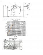
PP UL 6L6GC 25W Amplifier
I built a pair of these around 1960, they were in daily use for 17 yrs when they were replaced by a Sansui AU717 / TU717 Combo. Now on the shelf but both still in working order.
The PS is a Hammond 273BX, the rectifier a 5AR4, but for this series of tests the rectifier used is a plug in SS replacement. The filter is 40 microF / 1.5H Hammond 156R / 35 microF, the ripple at the OPT CT is 0.4 mV p-p.
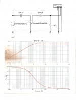
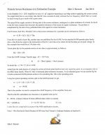
The 2-Tone Intermodulation (IMD) test is by the 3-4 method devised by Graeme Cohen. His 2008 paper covering it is here for those who might be interested.
At real power of 15.8 watts the IMD is down more than 40 db. This creates peaks of ~22 Watts. Clipping is > 30 Watts.
The front end is a 2-stage HF filter to reduce the effects of any LF transients caused by the various sources.
I built a pair of these around 1960, they were in daily use for 17 yrs when they were replaced by a Sansui AU717 / TU717 Combo. Now on the shelf but both still in working order.
The PS is a Hammond 273BX, the rectifier a 5AR4, but for this series of tests the rectifier used is a plug in SS replacement. The filter is 40 microF / 1.5H Hammond 156R / 35 microF, the ripple at the OPT CT is 0.4 mV p-p.
The 2-Tone Intermodulation (IMD) test is by the 3-4 method devised by Graeme Cohen. His 2008 paper covering it is here for those who might be interested.
At real power of 15.8 watts the IMD is down more than 40 db. This creates peaks of ~22 Watts. Clipping is > 30 Watts.
The front end is a 2-stage HF filter to reduce the effects of any LF transients caused by the various sources.
Attachments
-
 25W PP UL 6L6GC Amp w Captions.jpg162.3 KB · Views: 563
 -
3-4.ratio.distortion.measurement Graeme Cohen 2008.pdf815.2 KB · Views: 91
-
 6L6GC UL Amp Front End.jpg127.1 KB · Views: 478
 -
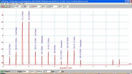 2-Tone Spectrum at Limits 15.8 Watts w Captions.jpg194 KB · Views: 442
 -
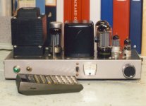 25W Amp Front.jpg74.9 KB · Views: 424
 -
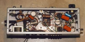 25W Amp Bottom.jpg82.5 KB · Views: 484
WOWOWOWOWOW!!!
Just a quick note to let you know that I am in a work shart-nado and can't respond right now. I should be out of it by the weekend. Thanks so much, rongon. You are amazing. I will review and have a more studies response shortly. Thanks also to jhstewart9 for your design and measurement docs. Great stuff.
Work is killing me right now but know that you are appreciated and that I will respond shortly.
Kofi
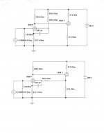
Driver Circuit in PP UL 6L6GC Amp
I tried this on the bench pre 1960, it looked like a good alternative. Much later when I had time I set up two different experiments to investigate this alternative circuit & the ordinary version. Not much to choose from, the results are about the same.
Later this driver shews up in one of the RCA tube manuals.
Attachments
OK, I tinkered. What I did was...
1) First file - Simple 6L6GC Amp v4.01.asc - I changed R10 and R20 from 680 ohms down to 560 ohms. That increased current through the 6L6s. They were dissipating 17W each before, now they're dissipating 20W each. That's still 10W below the max for 6L6GC and should be fine for 6P3S-E (the wafer based Sovtek '5881'). It would be right at the max dissipation for 6L6GB or 6P3S (the straight bottle, phenolic based Russian 6L6-oid), so if you're using those tubes as your output then this would not be a good idea. However, if you're using 6L6GC outputs, the THD is cut in half.
2) Second file - Simple 6L6GC Amp v4.02.asc - I changed the cathode resistors again, to add a 'harmonic cancellation' thing. That's R17 in the schematic. The idea is that R17 (33R 2W) is left unbypassed and shared between the 6L6 cathodes. R10 and R20 are reduced to 510R 5W. That's equivalent to each 6L6 having a 560R Rk, but it's been split. The result is suppression of odd harmonics in the output stage. Keep in mind that this in simulation, and is not guaranteed in real life.
Either way, increasing the current through the output stage lowers THD. Can you justify pulling 57mA through each 6L6 instead of 49mA? Would that break the power supply VA budget?
--
Totally, totally amazing. Looking at the results now and the distortion figures have really dropped. Thank you so much for your 'tinkering', rongon!
I would say that the 12AT7 cathode is a little close to 90V and makes me a bit nervous about violating the heater-to-cathode maximum, but I suppose I could always raise the heater voltage to accommodate.
It will be a little more expensive to service the increased current, but not too too bad. Obviously worth it for the distortion figures.
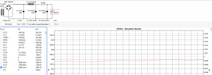
I'm thinking the Hammond 1650H would be OK for OPTs and I will likely use the Antek AS-3T350 toroid for the PTX.
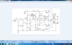
Attached a PSU design. Pretty simple, but feedback is welcome on this one as well.
Full parts list and design docs coming soon.
Thanks a million.
Kofi
Attachments
It's a question of 'Will the 12AX7 drive the 6L6GC Ultralinear outputs sufficiently well?'
That is actually a controversial topic around here. Some say the measly 1mA plate current of the 12AX7 is just barely enough to use to drive the 6L6GC UL finals. Others (including me) think that's not enough plate current to properly drive both the 6L6GC UL finals and the feedback loop without slew limiting on high frequency signals.
My *opinion* is that a 12AX7 used as the cathodyne/split load inverter would be a downgrade. A 12AU7 would work better (higher plate current possible with that type). If I had a choice, I'd use a beefier triode like 6CG7, 6N6P or 5687. But that's me. Others may say that's overkill. Certainly all these types use more heater current than the 12AU7 does, which might be an important consideration.
--
- Home
- Amplifiers
- Tubes / Valves
- 6L6GC UL PP Fun Time!