Hi, planning to start a tube amp build next autumn, hardwired and as basic as it gets - just to get my feet wet.
I have built several projects before, mainly SS amps, most recent was a PassDiy F3.
Never a tube amp though. I’m aware of the high voltages.
Any recommandations? Plan is to drive boxes with either alpair or small Fostex.
I have built several projects before, mainly SS amps, most recent was a PassDiy F3.
Never a tube amp though. I’m aware of the high voltages.
Any recommandations? Plan is to drive boxes with either alpair or small Fostex.
Last edited:
The 3-3 has a nice description over at r-type: Mullard 3-3. Three Watt Amplifier
Thanks!
What set me off in this direction was this gentleman’s website:
3W Single Ended Class-A Stereo Tube Amplifier – HEATED CATHODE
What set me off in this direction was this gentleman’s website:
3W Single Ended Class-A Stereo Tube Amplifier – HEATED CATHODE
Last edited:
Pentode amplifiers with long loop feedback (around two high gain stages plus an output transformer) are comparatively tricky to build. Folks do it and live to tell the tale, but it's somewhat trickier than lazy modern designs with less open loop gain, triode output impedances, and a grudging acceptance of resulting distortions.
Separately, modern sources don't really need such a high sensitivity. Nobody uses ceramic phono cartridges anymore, and that's the era that these Mullard circuits originated.
I don't want to come off as negative, but I just don't think that designs from this era, or from the 1980s or 1990s for that matter, are important anymore, except as historical lessons. That does sound negative, doesn't it? I'm sorry. But it's just not an ideal first valve amplifier project.
All good fortune,
Grumpy Guy Chris
The only change I would perhaps ensure you make if you take the original schematic is putting the fuse on the live side of the switch - ie mains live input -> fuse -> switch -> amp. That way if the switch shorts the fuse will blow. In your link they have done this.
It did occur to me to suggest a triode simple design first but I figured with your previous amp experience you'd probably be fine.
Lastly - know that tube schematics are like a dartboard given the variances of tubes, probably more so than the silicon alternatives. Plan in some adjustment variable resistors etc unless you're going down the full kit road.
Last edited:
Chis already mentioned most important issues with this design. . Poor open loop frequency response, far too high negative feedback, still far too high sensitivity. EF86 operates at starving voltages. If you have well equipped lab, then go ahead. If not, something more straightforward is my recommendation.
Something like this:

Something like this:
Last edited:
There is at least one Mullard 3-3 thread on this forum.
I agree with artosalo's comment about the voltage starved EF86.
And there were some recent builders who had problems with their EF86 not working in that circuit (tube OK, just not for that circuit).
I agree with Chris Hornbeck about high gain, and wrapping negative feedback around a less than ideal output transformer.
There are so many good circuits out there to try, and they are easy to build and they work at first power up.
All amplifier circuits can be made to look beautiful, boutique, etc., but they do not all work without a lot of help from this forum.
Just my opinions.
Chis already mentioned most important issues with this design. . Poor open loop frequency response, far too high negative feedback, still far too high sensitivity. EF86 operates at starving voltages. If you have well equipped lab, then go ahead. If not, something more straightforward is my recommendation.
Something like this:
I have a few 100x100mm boards for that circuit in the mail.
If OP needs any.
Attachments
I have built two Mullard 3-3s with excellent results. However the grid leak biasing is a little hit and miss. I don’t know if this is due to modern valves or whether this was also a problem in period. I have now modified them to conventional biasing, which the BBC also did back in the 1950s. Excellent transformers at reasonable prices are available from Primary Windings in the UK, which makes building any of the Mullard designs quite straightforward. The performance matches that published in the Mullard amplifier book. It’s difficult to explain why they sound so good when the measured performance is so modest. Perhaps modern speakers actually benefit from fairly low damping, I don’t know. Anyway, highly recommended.
pbb33,
Please Post the complete schematic of your modified version of the Mullard 3-3.
I suspect your modifications may be more than just a single resistor or two.
And please post the transformer model number, and any other changes you made.
Without the above information we are probably in for a lot of posts on this thread, in order to get coldcut's amplifier build working properly.
Or, coldcut can build any of a large selection of other simple but well proven amplifier designs.
artosalo's schematic in Post # 6, is one good example of just how simple an amplifier can be, and work and perform well.
Just my opinion.
Last edited:
Be aware that building a tube amplifier is not the same as building a solid state amplifier. Unless you have exactly the same output transformer you will need to adjust the feedback loop. If not having exactly the same laytout and output transformer you are likely to run into problems like ultra sonic spurious parasetics and the list goes on. I doubt that many know how exactly to test and adjust for those issues.
As others have mentioned the 3-3 as is has a few issues, I'd recommend just designing and building your own 3w amp, it's pretty straight forward.
Use solid state rectification though,however the power supply is one area that is a bit tricky for a low powered SE amp,you want it to supply as high a HT/B+ as poss without exceeding Va max to ensure full OP power.
I'd start with the best OPT you can lay your hands on, then start from there. All the info you need pretty much is over on - How to design valve guitar amplifiers
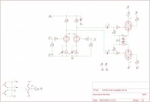
Lastly I've attached a schematic for a 3w amp I built, it may have not be perfect,it's the first attempt at designing an amp I did some years ago, the result though was very good,to my ears at least.
Andy.
Use solid state rectification though,however the power supply is one area that is a bit tricky for a low powered SE amp,you want it to supply as high a HT/B+ as poss without exceeding Va max to ensure full OP power.
I'd start with the best OPT you can lay your hands on, then start from there. All the info you need pretty much is over on - How to design valve guitar amplifiers
Lastly I've attached a schematic for a 3w amp I built, it may have not be perfect,it's the first attempt at designing an amp I did some years ago, the result though was very good,to my ears at least.
Andy.
Attachments
@ 6A3sUMMER
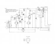
Just for information the modified BBC circuit (AM8-2/A) using cap coupling between the stages. And the information pdf.
@ coldcut,
I would not start my valve journey with the Mullard 3-3 circuit. There are plenty of suitable 'work first time' alternatives.
Just for information the modified BBC circuit (AM8-2/A) using cap coupling between the stages. And the information pdf.
@ coldcut,
I would not start my valve journey with the Mullard 3-3 circuit. There are plenty of suitable 'work first time' alternatives.
Attachments
Last edited:
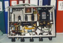
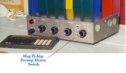
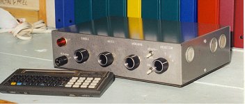
Did this one in 1968, its still running in the workshop today. Think the 6AQ5 was replaced once. And no problems at all with the NFB.")
Attachments
Alan4411,
Thanks for the schematic, and the posted article.
The first thing I noticed about the modified Mullard 3-3 schematic is:
The high frequency negative feedback path is . . .
Output transformer secondary to
C4 0.01 uF to
C1 25 uF to
The EF86 cathode and suppressor grid to
C10 220pF to ground.
Output transformer secondary drives
0.01uF drives
25uF drives
220pF to ground
Can anybody explain the purpose and function of C10, 220pF?
My guess is the re-designed amplifier was built near a high power RF transmitter or high power RF antenna tower.
For more evidence, look at the amplifier input low pass filter, a 1k Ohm series resistor and 220pF to ground, the filter connects to the EF86 control grid.
And, depending on the test equipment frequency, 1k in series with 220pf to ground does not measure to be 150pF at the input, but the article says it does.
How many more versions of modified Mullard 3-3 are there?
Why are they so popular?
Agreed: There are many many alternative simple and effective low power amplifiers out there - time tested and listened to with great enjoyment.
Get those feet tapping!
"You should make things as simple as possible, but no simpler." - Albert Einstein
Last edited:
Alan4411,
Can anybody explain the purpose and function of C10, 220pF?
That is to stop the highest impulses to reach the OPT. Can be seen when testing with square wave - less ringing.
This is the link to the Primary Windings site and article
The Mullard 3-3, an excellent choice for a first amp – Primary Windings
PS I have no connection to Primary Windings other than as a customer.
The Mullard 3-3, an excellent choice for a first amp – Primary Windings
PS I have no connection to Primary Windings other than as a customer.
As someone who built Mullard 3-3's a good 60 years ago (I was about 14) based on that green Mullard book, using Trimax output transformers and the layout suggested by Mullard, I experienced no issues.
They drove a pair of Rola 8mx's and fed from a Garrard turntable and Acos crystal cartridge. The family thought it sounded great.
However coming forward to 2021, there are better alternatives IMO. Something like the class A Hiraga or the JLH class A.
They drove a pair of Rola 8mx's and fed from a Garrard turntable and Acos crystal cartridge. The family thought it sounded great.
However coming forward to 2021, there are better alternatives IMO. Something like the class A Hiraga or the JLH class A.
- Home
- Amplifiers
- Tubes / Valves
- Mullard 3-3 for first time build- or better alternative?