Hi all,
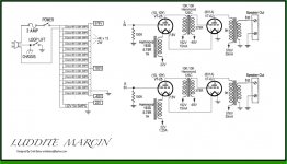
This summer I'll be plunging into the greenvalve design with 10y driving 801a, through hammond interstages and SMPS power supply.
I'll follow the schematic but will use 4 rod coleman regulators for the filaments.
This is my first DHT build, and how bias works is still beyond me.
What would you recommend? Filament bias on 10y, maybe with SIC diodes, and how many volts? And what to do with the output stage?
Any pointers on filament topology and values for this circuit are most welcome!
Cheers,
Simon
Attachments
I've built a few 10Y stages, including 2 or 3 with the 126C. In one of them I used 2 126C in series just as plate chokes. Ridiculous use of real estate but it did actually sound a little better.

My view would be:
- Use filament bias on the 10Y to avoid a cathode bypass and also to avoid SIC diodes, which I ripped out of all my equipment and replaced with resistors. Better sound, smoother and more musical. The SIC diodes had a kind of glare I couldn't live with.
- Use just the primary of the 126C as a plate choke and use a Russian FT-2 or FT-3 coupling cap. You'll get a cleaner and better sound. Incidentally, you can't add the primary and secondary to make a larger value plate choke. Doesn't work in practice, and believe me I tried all ways.
- Use one supply with Rod Coleman regs for each tube. So total 4 supplies.

For any cathode bypass caps, use DC Link caps. Vishay or Kemet I've used and sound great. I haven't tried Epcos or Wima DC Link caps but they probably sound equally good. I never used an 801A in the output so no comment there. Anyway, you should get good sound, though not too much output. I know nothing of A2 operation, but I know that works and I've heard it in a high sensitivity horn system sounding very nice. Maybe others could say a word about that and include a schematic.
.
My view would be:
- Use filament bias on the 10Y to avoid a cathode bypass and also to avoid SIC diodes, which I ripped out of all my equipment and replaced with resistors. Better sound, smoother and more musical. The SIC diodes had a kind of glare I couldn't live with.
- Use just the primary of the 126C as a plate choke and use a Russian FT-2 or FT-3 coupling cap. You'll get a cleaner and better sound. Incidentally, you can't add the primary and secondary to make a larger value plate choke. Doesn't work in practice, and believe me I tried all ways.
- Use one supply with Rod Coleman regs for each tube. So total 4 supplies.
For any cathode bypass caps, use DC Link caps. Vishay or Kemet I've used and sound great. I haven't tried Epcos or Wima DC Link caps but they probably sound equally good. I never used an 801A in the output so no comment there. Anyway, you should get good sound, though not too much output. I know nothing of A2 operation, but I know that works and I've heard it in a high sensitivity horn system sounding very nice. Maybe others could say a word about that and include a schematic.
.
Last edited:
Any advice that isn't just spitting out what I did and thinking you should buy into needs to start with a question. How much time do you have and what's your goal?
Are you interested in exploring differences in sounds and the electronics used to get them or are you wanting to get quickly to a set-up and stay there? I suppose it wouldn't hurt to ask if you've heard the Greenvalve circuit in person.
Are you interested in exploring differences in sounds and the electronics used to get them or are you wanting to get quickly to a set-up and stay there? I suppose it wouldn't hurt to ask if you've heard the Greenvalve circuit in person.
48V bias for 1.25A filament current will result in 60 VA wasted plus the normal filament power. I would never use filament bias with this kind of tube. That's the filament consuption of 2x 845 tubes!

If want to do all with one supply voltage could use back-bias where the resistor is between the first and second filter capacitors (on the negative side) and the ground is at second capacitor. This way the current thorugh that resistor is the total anode current (and the negative voltage will be taken at the first capacitor and then well filtered), hence much less power wasted.
If this is not possible because of the SMPS supply then cathode bias with RC.
Code:
I've built a few 10Y stages, including 2 or 3 with the 126C. In one of them I used 2 126C in series just as plate chokes. Ridiculous use of real estate but it did actually sound a little better.
My view would be:
- Use filament bias on the 10Y to avoid a cathode bypass and also to avoid SIC diodes, which I ripped out of all my equipment and replaced with resistors. Better sound, smoother and more musical. The SIC diodes had a kind of glare I couldn't live with.
- Use just the primary of the 126C as a plate choke and use a Russian FT-2 or FT-3 coupling cap. You'll get a cleaner and better sound. Incidentally, you can't add the primary and secondary to make a larger value plate choke. Doesn't work in practice, and believe me I tried all ways.
- Use one supply with Rod Coleman regs for each tube. So total 4 supplies.
For any cathode bypass caps, use DC Link caps.Thanks a lot for your input, Andy! I'll follow your 3 advices and will draw up a schematic for scrutiny later on. I've read a lot of your posts and appreciate your expertise.
Code:
How much time do you have and what's your goal?My goal with this one is to get a taste of the thoriated tungsten tubes on hand with an astonishingly easy design.Time and resources are limited, just want to get my feet wet. I haven't heard the greenvalve design. Building it will allow me to do so
 Not afraid to tweak, but I have to start somewhere.
Overall I prefer a compromised easy implementation over an elaborate design I'll never build. Any tips to reduce the compromise, respecting the overall simple topology: please shoot
Thanks!
Simon
Last edited:
Code:
48V bias for 1.25A filament current will result in 60 VA wasted plus the normal filament power. I would never use filament bias with this kind of tube. That's the filament consuption of 2x 845 tubes!
If want to do all with one supply voltage could use back-bias where the resistor is between the first and second filter capacitors (on the negative side) and the ground is at second capacitor. This way the current thorugh that resistor is the total anode current (and the negative voltage will be taken at the first capacitor and then well filtered), hence much less power wasted.
If this is not possible because of the SMPS supply then cathode bias with RC.Thanks 45, I get the rough idea and will take it into consideration when drafting a schematic for the filaments. I did order some extra smps supplies, so a separate PS for bias is an option.
Simon
Last edited:
Any advice that isn't just spitting out what I did and thinking you should buy into......
I've built a lot of this stuff and learned several practical things in doing so. I'm trying to help here, and pass on some of the things I encountered during actual builds. It's one thing looking at a schematic and another thing actually building it and listening carefully to the results, and then trying out variations on it, all of which I would have thought was a bit obvious.....
48V bias for 1.25A filament current will result in 60 VA wasted plus the normal filament power. I would never use filament bias with this kind of tube. That's the filament consuption of 2x 845 tubes!
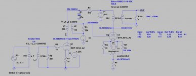
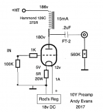
That would be true of 48v bias as you say. But it depends on your operating point for the 10Y. I used a 19v supply to Rod's regs and an operating point of 175v, -5v and 15mA which suits the 126C. Ale used a similar operating point and a 17v supply as you can see here. It sounds just fine. Not the only way to do it, but one way.
Attachments
My goal with this one is to get a taste of the thoriated tungsten tubes on hand with an astonishingly easy design.Time and resources are limited, just want to get my feet wet. I haven't heard the greenvalve design. Building it will allow me to do so
Overall I prefer a compromised easy implementation over an elaborate design I'll never build. Any tips to reduce the compromise, respecting the overall simple topology: please shoot
Thanks!
Simon
Well , taking you at your word and not being sure what you mean by "compromise" I can't offer more , especially as it's still not entirely clear to me whether you want to take a heli to Everest or climb it yourself. No problems with either approach but not knowing which it is, it's hard to know whether to recommend a helicopter service or climbing school.
That circuit isn't the only way to hear what a DHT sounds like. If you have other tubes on hand, especially in a previous build with already existing power supply. . . . .
I've built a lot of this stuff and learned several practical things in doing so. I'm trying to help here, and pass on some of the things I encountered during actual builds. It's one thing looking at a schematic and another thing actually building it and listening carefully to the results, and then trying out variations on it, all of which I would have thought was a bit obvious.....
If you're posting the above because you think I'm referring to you, you didn't read my post. It's not about you. To quote my post " Any advice that isn't just spitting out what I did and thinking you should buy into needs to start with a question."
As explanation for my post: I might have a word to put in toward what the OP seems to be asking about , but I don't want to waste anybody's time with my own musings if they don't relate to the real question and, more importantly to me, I want to give whatever I can to support honest exploration at the simplest level, something that is often discouraged by those who think knowing is better than asking. (Again, not referring to you)
So it seems to me to be an important question, do you want to go directly to whatever circuit is the present day equivalent status of the "Ongaku", or are you interested in exploring differences in the sound reproduction and how it's affected by the circuitry? Without knowing which one it is, how can you answer? And especially if it's the latter, why would you direct them to bypass all the learning they could do by going straight to the Ongaku?
For example, the OP states his intention is to get a taste of DHT sound. Will he really get which is the DHT sound and which is the Coleman reg's contribution if he starts out with both at the same time? You've been around the block a few times. What do you think?
I have used the multiple 48v smps units which you can read about here. Remember that I was trying to make the amp lightweight so that I could carry it.
Audio ratbag: The heart attack special - 6S17K-V powerdrive GK71 SE amplifier
We moved to Australia from the US last year and I disassembled the amp. I will probably rebuild it sometime but I will do the smps units differently. For the first version, I cut open the smps units which was a real pain in the neck. In the next version, I will not cut them open, but use insulated spade connectors to connect to the AC prongs. The ground prong is not connected. I used a flat head screwdriver to loosen the spade connectors slightly to fit the prongs.

You have to be careful with the wiring, particularly stringing the positive and negative DC wires.
Since you are experimenting, use some sort of breadboarding technique so that you get a sense of how much room you will need in the final amp. You might like to try some different ways of powering the filaments before ending up with Rod's modules. In addition to 6-volt smps units, you might take a look at the D-Noizator thread in the power supply forum.
D-Noizator: a magic active noise canceller to retrofit & upgrade any 317-based V.Reg.
ray
Audio ratbag: The heart attack special - 6S17K-V powerdrive GK71 SE amplifier
We moved to Australia from the US last year and I disassembled the amp. I will probably rebuild it sometime but I will do the smps units differently. For the first version, I cut open the smps units which was a real pain in the neck. In the next version, I will not cut them open, but use insulated spade connectors to connect to the AC prongs. The ground prong is not connected. I used a flat head screwdriver to loosen the spade connectors slightly to fit the prongs.
You have to be careful with the wiring, particularly stringing the positive and negative DC wires.
Since you are experimenting, use some sort of breadboarding technique so that you get a sense of how much room you will need in the final amp. You might like to try some different ways of powering the filaments before ending up with Rod's modules. In addition to 6-volt smps units, you might take a look at the D-Noizator thread in the power supply forum.
D-Noizator: a magic active noise canceller to retrofit & upgrade any 317-based V.Reg.
ray
What would you recommend?
Forget this schematic!
10Y hasn't enough gain (has approximately gain 8) to drive 801a in two stage amplifier.
801a bias is 48V, so it's requiring at least 8V peek input signal.
On the other hand series connection of -large cathode current- DHT tube's filament is designing mistake, occurs feedback between tubes.
The critical point of using 801a as SE is the OPT.
If you use it in A1 region, requiring 10k...14k -good- transformer, which is rare and expensive.
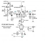
Instead it I used PSE (paralleled 801a power tubes) with 5k transformer and large gain VAS stage (841/VT51 tube), and cathode or source follower.
The other solution is using 801a in A2 mode (zero bias) as L0rdGwyn had:
801A in Single-Ended A2 - Design and Build
So it seems to me to be an important question, do you want to go directly to whatever circuit is the present day equivalent status of the "Ongaku", or are you interested in exploring differences in the sound reproduction and how it's affected by the circuitry? Will he really get which is the DHT sound and which is the Coleman reg's contribution if he starts out with both at the same time? You've been around the block a few times. What do you think?
Good post and good points you raised. Are you asking me, or everyone, or the OP? If it's me I'd use a plate choke (126C is fine for that, or 126B for more current, or a LL1668/15mA or 18mA, or something more exotic) and a FT-2 coupling cap. Different operating point to suit filament bias. Or to simplify it even more, drop the filament bias and use a cathode bypass cap for which I favour DC Links. I would use Rod Coleman regs, which are widely used and highly rated for DHTs. All very simple, which is what the OP wants. I can't comment on the Ongaku type schematic he first posted, and I agree with euro21 that you should start in a different place for the reasons he gives. But I don't think (?) the OP is specially attached to it - more to the idea of a 10Y into an 801A which is fine if the speakers can support it (???). Again, there are A2 solutions for which there's an active thread already so that's another way to go. In practical terms, for the input 10Y I'd make separate filament supplies in a different box and link them with XLR 4 pole connectors. This allows me to use choke input filament supplies when using filament bias - gives an even purer sound specifically when you use filament bias. Not so important in ordinary self bias - Rod's regs are enough. But overall I'd use a 300b output tube with a triode input tube with a mu of 30 or more. 10Y and 801A are expensive, and I'd put the money into better OPTs with a plain old 300b. That's my personal preference after 12 years of building with DHTs. But that's another concept altogether.
.
Last edited:
Some thoughts :
I think Klimon's posts are pretty straightforward. An important detail to start with is that he says he already has the 10Y and 801 in hand. The only thing I'm not sure of is how much he wants to explore. I get others' objection to the schematic but as long as he doesn't try to make a monument out of the build (I agree with Ratbagp's breadboarding suggestion.) , maybe it's best just to help him go ahead with it as is and see what he thinks. After all, Larry Moore's 10 squared amp (10 driving 10) was somewhat famous in its day, and my guess it was the inspiration for the Greenvalve circuit. We both know he's not going to find long lasting perfection in his first DHT amp (or will he?) but once built he might come back with comments and then go on to address whatever he feels are its shortcomings.
I don't agree with stacked switchmode supplies for a builder who doesn't yet know what bias is about.
To be honest, I think if he's already built other tube amps, he'd be better off to see if he could use one of the DHTs as a driver or output in a circuit he already knows the sound of to hear what difference it can make.
In a vacuum, I'd say start with 10 or 801 as the output and an idht with gain and transconductance as the input/driver . No fancy bias , no fancy anything.
Of course there's a LOT more that can be talked about but it's all dependent on what he has to say. nudge nudge
Hi all,
Great to have your attention Let me take it one step back:
- I've been collecting 10y, 801a and 841 for some years now and want to put them to use without breaking the bank or my head
- power will be enough for my 98db/w speakers
- I'm quite set on this design: elegantly simple + I want to try the smps thingy + already ordered hammond 126c, edcor 8ohms to 10k (better exists, but at what cost) and the Cisco smps' greenvalve used
- I will use 4* rod coleman because of its reputation and clear instructions, I have 'em on hand + as Euro21 remarked: I didn't trust the filament connection & supply in the schematic
- I've been building and tinkering with tube amps for years. Like another member wrote: I'm more of a cut and past guy than an engineer. It works for me, with the priceless help from you guys
@Andy: thanks for your advice and 10Y bias schematic, I'll use that one as a blueprint and go with cathode bias with DC link for the output
@Hearinspace: I hope I answered your heli / climbing school question with the info above. Curious to hear your remarks on the circuit.
@Euro21: Thanks for your assessment of the gain. I'll also build a preamp then. You published two schematics here with 841 - 10Y or source follower - 801a PSE which got my attention, but are too complicated for me at this point. Same goes for L0rdGwyn's elaborate design. I don't have enough tubes either to find matching PSE pairs.
@ratbagp: Great info! I'll follow your advice on connection & wiring. Space is not a problem.
Cheers (let it rip) !
Simon
Great to have your attention
Let me take it one step back:- I've been collecting 10y, 801a and 841 for some years now and want to put them to use without breaking the bank or my head
- power will be enough for my 98db/w speakers
- I'm quite set on this design: elegantly simple + I want to try the smps thingy + already ordered hammond 126c, edcor 8ohms to 10k (better exists, but at what cost
) and the Cisco smps' greenvalve used- I will use 4* rod coleman because of its reputation and clear instructions, I have 'em on hand + as Euro21 remarked: I didn't trust the filament connection & supply in the schematic
- I've been building and tinkering with tube amps for years. Like another member wrote: I'm more of a cut and past guy than an engineer. It works for me, with the priceless help from you guys
@Andy: thanks for your advice and 10Y bias schematic, I'll use that one as a blueprint and go with cathode bias with DC link for the output
@Hearinspace: I hope I answered your heli / climbing school question with the info above. Curious to hear your remarks on the circuit.
@Euro21: Thanks for your assessment of the gain. I'll also build a preamp then. You published two schematics here with 841 - 10Y or source follower - 801a PSE which got my attention, but are too complicated for me at this point. Same goes for L0rdGwyn's elaborate design. I don't have enough tubes either to find matching PSE pairs.
@ratbagp: Great info! I'll follow your advice on connection & wiring. Space is not a problem.
Cheers (let it rip) !
Simon
Last edited:
nudge nudge
I see we cross-posted. Hope you'll find the answers in my previous post.
I doesn't have to be perfect, just as perfect as it can be with the proposed basic circuit and parts. 'The best is the enemy of the good'
Best... I mean good
If you have Edcor 10k:8, this is one of the acceptable solution.
Looks like an elegant way to get into A2 with only two stages. But the added cost of the other interstages & input xformers plead against it for now. Glad to see you consider the edcors as viable candidates!
With all the comments so far and input to amend the circuit, I'm feeling confident the basic design + C-coupling + coleman regulators and practical tips for the smps implementation will get me somewhere good.
Will I need some kind of HV delay or inrush current limiter to increase tube life? The coleman regulators are slow start I think, but I hear the tungsten filaments are quite vulnerable. Not switching them on and off too often will also be part of the special care...
Cheers
Simon
- Home
- Amplifiers
- Tubes / Valves
- Greenvalve 10y into 801a