Change the bloody cap to at least 0,22uF PIO.
What about your PSU?
@Schmitz77: 6N6P or 6N30P are unbeatable no matter which pentode in comparison, gone that way. Pentode klingt scheisse...")
OK, haven't tested and audited this tube.
You're talking about university so apparently you are clever enough ....
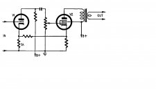
Well done to draw the red dots; however these connections are obvious...no place to go elsewhere.
There are two "crossings" of lines where it might have been better to follow normal drawing protocols but it is obvious enough as it is, at least to be able to read the schematic correctly.
Biggest problem in my view is the 0.015 uF capacitor / 680 k resistor combo, which makes a 15 Hz high pass.
Why don't you understand, most important question is always: how can the problems of the customer can be solved?
I don't have any problems with misinterpretations, as you saw.
But I wouldn't have problems with debugging this amp either.
So your going straigth in the wrong direction.
Any company who produces industrial goods is establishing a quality control system. And that would beware the company to use schemos like this. Because its prone for establish faults in the production.
And that may lead to the problems of this gentleman with his gear.
Btw, biggest problem isn't the 0.015 uF capacitor / 680 k resistor combo. It's just not the biggest problem- it's no problem at all.
Last edited:
Haha, trying to help solve the problems is exactly what I did by pointing to the R/C combo giving the wrong high pass.
First check if the amp has sufficient bandwidth before the output transformer (the output transformer being the limiting factor but in this case will perform well).
It does not help CoolJazz at all to bash the drawing, or bash the pentode input stage.
First check if the amp has sufficient bandwidth before the output transformer (the output transformer being the limiting factor but in this case will perform well).
It does not help CoolJazz at all to bash the drawing, or bash the pentode input stage.
We all know that the problem you describe is no problem.
Do you have expertise in audio design?
That combo doesn't make for a limited bandwith. If so, all other commercial amps would have this done false.
But I told you already.
Btw, thats the reason, why plans aren't written the way this plan has been written. Do you get the idea?
How many possible interpreations would this plan have without the dots?
Attachments
Last edited:
That combo makes for a 15 Hz high pass, which is an engineering mistake compromizing the performance.
Together with the bandwidth of the output transformer it might give unsufficient bass response at the output of the amplifier.
Funny drawing you come up with...
The dots are not necessary; the two crossing could have been drawn better, but you don't even have to be a university student to grasp....
Together with the bandwidth of the output transformer it might give unsufficient bass response at the output of the amplifier.
Funny drawing you come up with...
The dots are not necessary; the two crossing could have been drawn better, but you don't even have to be a university student to grasp....
Last edited:
I tested C26 and C24, capacitance measurements are good.
Did you check R29/30?
68k instead 680k makes 156 Hz high pass...
You did not show the power supply schematic.
I bet before the tubes warm up, the B+ is more than 400V (solid state diodes, no load).
And the bias is -35V.
C25 and C26 are subjected to at least 435V before the tubes warm up.
But they are only rated at 400V. They may be leaky by now.
Use a 600V or 630V part.
Back to your loudspeakers, what is the make and model?
What is the minimum impedance in the bass region?
(may vary a lot versus frequency, but sometimes as low as the DCR).
. . . Get your Ohmmeter out, measure the DCR. Probably the impedance from 20 to 35 Hz is the same as DCR, and probably at about 150 to 300 Hz is the same as DCR.
That can sound thin, example, if the speaker is rated 8 Ohms, but has 4 Ohm DCR.
Then on to the output transformer.
What make and model?
Is it rated for 84mA DC?
(the quiescent current of your schematic)
How heavy is the transformer?
**************
I finally read most of the posts. Monolith Magnetics makes very good output transformers.
However . . . if you use their 60mA 300B version, it will sound thin if you put 84mA quiescent DC in it.
It will be badly saturated.
57V/680 Ohms = 84mA.
****************
Then on to your ears (most peoples ears).
at sound levels of 60 to 70 dB, the Fletcher Munson curves take over. Ears at that volume do not hear low frequencies.
I call it Fletcher's Munching Effect.
The low note on an electric bass guitar is about 41Hz. That is plenty low to have a strong bass sound.
20Hz or 30Hz is for 32 foot pipe organ pedal notes (most organs do not go there).
Hopefully we landed on one thing or more that is causing the problem.
Last edited:
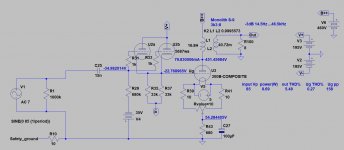
The bias is not -35V.
Fixed bias is -23V (grid, relative to "ground") and cathode bias is +57V (cathode, relative to "ground"), so overall bias (grid relative to cathode) is -80V.
Monolith S-9:
single ended output transformer
3300 Ω to 4 and 8 Ω
optimized for 3 0 0 B type power triodes in 10 Watt mode
(400V 80mA condition)
Primary DCR: 107R so anode at 451V.
Anode-cathode voltage: 394V.
300B operating point:
-80V, 394V
Current from datasheets (depends of manufacturer): 80..85mA.
IMHO schematic and bias point are OK.
Last edited:
-Check schemo for correct build without ANY errors
-Check values of parts to build with before building
-Check circuit for correct theory of operation before building, not afterwards
-Check voltages in real vs. voltages of schemo
Thats the part of the amp. If anything is OK, the amp is OK.
Then follows the other parts of the whole audio system
-Check speaker and source for compatability
-Check room- speaker interaction
If a mismatch is somewhere, this can cause the wrong sound, even when the amp is OK.
Every DIY should be able to do those basic checks of gear. Otherwise don't do DIY.
Its like buying a car without having the knowledge and licence to DRIVE.
You should have at least: Digital/analog Multimeter.
Better: Oscilloscope, signal generator, Multimeter
We have learned to troubeshoot small faults in very complex gear.
The procedure is always the same fo find the fault.
Every DIY should learn this. Without it, a forum can't do the basic teaching. Just give hints.
For basic learning, there are primers on every subject on the internet.
But most people don't want to learn for themself those basics. Because its easier to go into a forum and put the basic questions there.
But a forum is a forum and not about teaching the basics again and again with every new project.
And this feels on both sides like "nobody is competend to find my fault".
Because its not the correct method that can be applied on a forum without knowing nothing about the amp and its surrounding.
To me, this will always be a mediocre sounding amp. Because the circuit isn't first class.
Last edited:
The driver and output section IMHO is correct design ... apart from mixed bias (I prefer fix bias method).
Not the lowest distortion amp, but tolerable.
The - simmed 14.5Hz - LF limiting due to the 15nF - 680k.
Increasing the capacitor, or decreasing the resistor also helps.
It's another problem, that practically no sound.
The thin, weak "chirping" can come from many things:
- no real input, only crosstalk;
- bad implementation (bad parts, misconnections etc.);
- the loudspeaker is requiring biwire bridging or cabling;
- etc....etc...
Attachments
Thanks for all your thoughts and hints. It gave me some direction and I might have thought up a possible issue with signal input grounding and/or the grid resistor(s) R19 and R17. Going to check that later today.
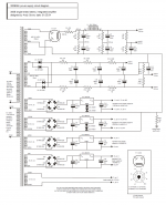
I've attached the PS schematic for good measure.
Supplies for the heaters is different, I'm using Pete Millet's regulated filament supplies (x4).
Primary on the PT is 440V instead of 460V, my choke has about 100ohms less resistance.
With some of you discussing C25+R29 filtering out anything below 15hz, what benefit is there having a lower cut off? I don't think I'll ever own a speaker (or ears) that can render anything below ~20hz
Attachments
Last edited:
Thanks to various comments made here I found the issue. I screwed up with a ground wire, basically bypassing R17/18 so pin 9 on V1 &V2 only saw 1K to ground instead of 1M.
Another lesson learned
Really appreciate all your help.
It's still like to hear more about the high pass of 15hz and why maybe it's not ideal.
Another lesson learned
Really appreciate all your help.
It's still like to hear more about the high pass of 15hz and why maybe it's not ideal.
Thanks for all your thoughts and hints. It gave me some direction and I might have thought up a possible issue with signal input grounding and/or the grid resistor(s) R19 and R17. Going to check that later today.
I've attached the PS schematic for good measure.
Supplies for the heaters is different, I'm using Pete Millet's regulated filament supplies (x4).
Primary on the PT is 440V instead of 460V, my choke has about 100ohms less resistance.
With some of you discussing C25+R29 filtering out anything below 15hz, what benefit is there having a lower cut off? I don't think I'll ever own a speaker (or ears) that can render anything below ~20hz
Just some tips for better sound:
To put elcaps in series is a bad idea, one cap with higher voltage rating instead of 2 in series sounds much better and faster. Even better use MKPs like Solen 100uF/630V with a 0,22uF PIO.
Replace the first resistor after rectifier (47R) with a choke. That will lead to more body, better textures and easier sound. If you dont want to buy another choke put your existing choke in that position and use a resistor in the old choke position. Beware of voltage dropping after changes. If you dont use Lundahl chokes you give up at least 50% sound quality.
Last edited:
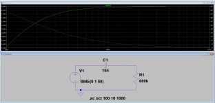
As you can see, the 15Hz highpass filter has -3dB at 15Hz, but till to 100Hz modifies the transmission.
If you lower this breakpoint, this interference decreasing in the audible range.
But using too low lower breakpoint also be avoided.
Absolutely. Change that bloody cap to 0,22.
As you can see, the 15Hz highpass filter has -3dB at 15Hz, but till to 100Hz modifies the transmission.
Thanks, what's that program you're using?
Thanks, what's that program you're using?
LTSpice.
- Status
- This old topic is closed. If you want to reopen this topic, contact a moderator using the "Report Post" button.
- Home
- Amplifiers
- Tubes / Valves
- Help debug 300B amp, thin sound, low volume