@ jhstewart9: Both your preamp drawings show a MAG. PHONO IN. But where's the RIAA equalization with it's two time constants, at least?
Mesnwhile I've searched through Wikipedia, the obvious one, chapter Miniature tubes, and found out that 6J6 was among the first B7G tubes that were introduced in 1939 by RCA. Hence, and especially from the United Statesian point of view, it was a pre-war tube.
Best regards!
The amplifier front end was used primarily with a GE Variable Reluctance pickup, very popular at that time. Part of the equalization curve is got by running the pickup into 6.8K. The other part of the curve results from the NFB from the 2nd plate to the first cathode, the RC network rolloff is ~1000 Hz. The other example posted here was marketed to users who already had a compatible amplifier. I recently gave this piece away, still working.
Attachments
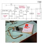
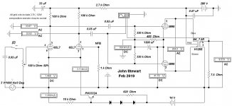
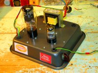
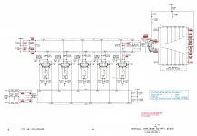
The Electra Print SE 6BX7 amplifier is unlikely to deliver 4 Watts of audio. Early in 2019 I did a series of tests on several octal twin triodes in PP configuration looking for best possible performance without NFB. The tubes tried were 6SN7, 6BX7, 6BL7 & 5998. They all have the same socket connexions. The 6BX7 managed an honest 3 Watts in PP just below clipping, without exceeding the plate dissipation spec. SE amps are normally not as efficient as PP amps. Your 6J6 would sub right into this circuit & drive any of these tubes to clipping.
Attachments
-
Here are the Results for the PP 6BX7 version of the amplifier.doc23.5 KB · Views: 56
-
6BX7GT.pdf328 KB · Views: 60
-
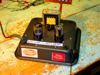 6SN7 Amp Betty Crocker Special.jpg589.9 KB · Views: 247
 -
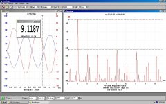
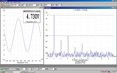 PP 6BX7 260V PS 3 Watts.JPG133.1 KB · Views: 248
 -
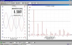
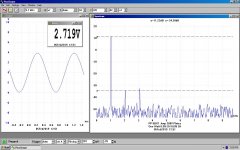 PP 6BX7 260V PS One Watt.JPG129.5 KB · Views: 259
 -
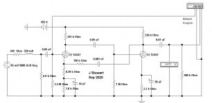
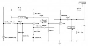
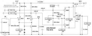 PP 6BX7 Amp Schematic.JPG76.8 KB · Views: 312
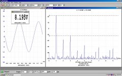
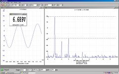
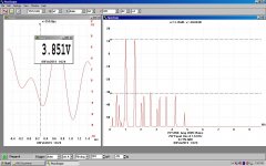
The THD is read by HP 334A. IMD & D traces by PicoScope 3224. Power Watts by MetraHit 29S Precision DVM & Wattmeter. I used 80 Hz in the IMD tests so that any 60 or 120 Hz from heaters would appear separately. The power is provided by a home grown regulated PS.
Attachments
-
 PP 5998 Amp w NPN Drain to -14V.JPG80 KB · Views: 112
 -
 PP 5998 Amp 11 Watts OPT Taps 1-5.JPG133.5 KB · Views: 46
 -
 PP 5998 Amp 10 Watts OPT Taps 1-5.JPG131.1 KB · Views: 41
 -
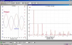 PP 5998 Amp 7.5 Watts w Captions.jpg241.3 KB · Views: 40
 -
 PP 5998 Amp 9 Watts.JPG125.6 KB · Views: 49
 -
 PP 5998 Amp 6W 1.46% 3H.JPG121.6 KB · Views: 41
 -
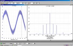 PP 5998 Amp 3 Watt IMD 80 Hz & 5 KHz.JPG130.1 KB · Views: 49
 -
 PP 5998 Amp 2 Watts Equal One & 1.6 KHz.JPG123.3 KB · Views: 61
 -
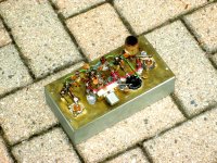
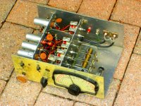
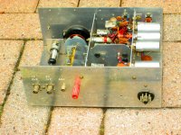
 IMG_3996 Betty Crocker 5998 Version.jpg504.6 KB · Views: 80
 -
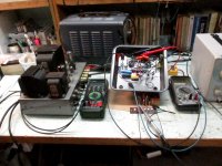 IMG_3994 Betty Crocker on the Bench.jpg363.3 KB · Views: 95
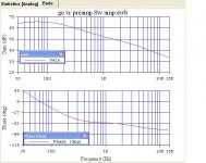
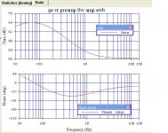
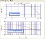
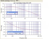
GE Variable Reluctance Pickup Response Curves
Out of curiosity I ran a simulation on the phono preamp in my very old 8W amp. There are three curves, one shewing the pickup & its 6.8K load resistor, then the response of the following 2-stage 12AX7 amplifier. The final curve is the entire path. Don't know how close this comes to the correct equalization but it sounded OK at the time it was used. Especially after a couple of alcoholic beverages!
Out of curiosity I ran a simulation on the phono preamp in my very old 8W amp. There are three curves, one shewing the pickup & its 6.8K load resistor, then the response of the following 2-stage 12AX7 amplifier. The final curve is the entire path. Don't know how close this comes to the correct equalization but it sounded OK at the time it was used. Especially after a couple of alcoholic beverages!
Attachments
Currently I'm reading George Dyson's book Turing's Cathedral in it's 2012 German edition. Chapter 7 describes the development of the IAS machine, an early computer, driven by 3474 vacuum tubes. Among them were 1979 pc. of 6J6 tubes, configured as flipflops. John von Neumann (Johann Neumann von Margittai, as he was Hungarian origin) and his co-designers bought these tubes from WWII military surplus, as Dyson says.
The 6J6 caught my interest, as it has been my very first contact with tube circuitry in my early youth. It's got a rather unusual construction: It has a rectangular cathode sleeve, both triodes were places at the the long sides of this rectangle each. Does anyone know the application(s) it has originally been designed for? And, as the book and some other informations I got gave me some thinking, am I right in my assumption that this tube was the first one with the 7-pin B7G socket, and that B7G tubes in general were preceeding the B9A Noval tubes?
Best egards!
At very high frequencies lengths of electrodes matter a lot, adding inductance. That's why were designed tubes for push-pull stages, with almost zero inductance between cathodes.
The 6J6 in Amatuer Radio
During the 50's many amateurs & others used the 6J6 in home grown small transmitters & receivers. They were useful as oscillators & mixers in many frequency convertors shifting 10m, 6m & 2m signals into the broadcast band.
I never did anything at 2m but did build a crystal controlled 6m converter. This one had a broadband 6m front end using a 6CB6. The oscillator convertor is a 6U8. The IF is another 6CB6 covering the broadcast band. So the BC receiver tunes the 6m band directly. It hasn't run in many years, the correct crystal is lost.
Attachments

BC receiver ?--- yes I had a BC-348 communications receiver bought at an ex Army /RAF/Navy store in the 50,s .
An American receiver it was built like a tank and converted to UK mains operation ,only drawback was its limited shortwave coverage but otherwise a very good receiver .
If I remember correctly ( correct me if I have memory failure ) it had an earth isolated bias , its just a pity the "built like a tank " engineering typical in USA equipment and also domestic equipment of the 50,s went downhill just like the UK.
I found out it was all down to profit ---even in the Armed Forces !
BC-348 Dynamotor Part 1
yes I had a BC-348 communications receiver bought at an ex Army /RAF/Navy store in the 50,s .
I got my BC348 from Fair Radio Sales in Lima OH -- I think it was $80 -- money I made from cutting lawns. It was OK, not great. I was able to move up to a Hammarlund HQ140XA a bit later.
Jan had mentioned a book to me several weeks ago, and I was able to locate a copy: "Handbook of Electronic Control Circuits" edited by John Markus, 1959. If you want to know how to control the firing rate of machine guns (600 rounds per minute) this is your book! High gain differential op amps etc.
Somebody is reading it in Open Library and The Library of Congress says you must check in.
I did have several Hallicrafters including the SX28.
In the UK you can be jailed for having information on obtaining guns and weapons, one guy imported a gun from the USA via an online seller he first knew about it when his door was knocked in and he was arrested.
I did have several Hallicrafters including the SX28.
In the UK you can be jailed for having information on obtaining guns and weapons, one guy imported a gun from the USA via an online seller he first knew about it when his door was knocked in and he was arrested.
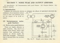
When I wrote BC receiver, I meant Broadcast Receiver, not one of the BC series of WW2. Many of these convertors were installed in the experimenters car to act as a mobile unit. So the broadcast receiver became a kind of 2nd IF. Ignition noise was a real problem, so the in car receiver needed a noise suppressor in the audio path. The one I used tracked the signal strength. I built two other convertors, one a general coverage, 3-30 MHz & another, a 40m rig.
Attachments
For dual common cathode VHF tubes like the 6J6, one should also mention the Amperex 7699 dual beam pentode.
It was used in the Tektronix 581 and 585 Oscilloscopes as the vertical deflection output stage. The 585 was a 100 MHz Scope. The 7699 tube is rated on the Amperex data sheet as good to 500 MHz.
(the beam plates are connected to the cathode internally, not shown on the tube diagram, and internal capacitance neutralization is provided)
https://frank.pocnet.net/sheets/201/7/7699.pdf
I'm not too impressed with the linearity of the curves on the data sheet, but somehow Tek got 1% without N Fdbk.
Attachments
Each 6DJ8 is in balanced mode. That means the 2nd order distortion is partially cancelled.
And, then the distributed amplifier topology used to get more gain was a great engineering solution.
Later, distributed amplifier topology was implemented in both BJT transistors, and even later in GASFETs (the GASFET distributed amplifier was done by Tektronix subsidiary, Triquint, that later spun off).
The 7699 was in differential mode, even though the common cathode resistor was only 1.1k Ohms. That means the 2nd order distortion is partially cancelled.
Even without the common cathode resistor (and with more complex biasing), the circuit would have been balanced, and the 2nd order distortion would be partially cancelled.
Yes, cancellations are only partial, but 1% accuarcy was both a noble goal, and tough to achieve.
Perhaps the greatest engineering feat on this amplifier is that it is all DC coupled, with 5 6DJ8s in parallel, and driving the 7699.
But even more than that . . .
It is DC coupled all the way from the input connector, to and through the preamp, to the delay line, and then to the 6DJ8s and on to the 7699.
Last edited:
Tektronix had the first 1GHz scope.
It used a delay line that fit in several 15 Inch turns of a 1 inch "pipe".
The input was differential.
There was no active "amplifier".
The only 'amplification' was the Distributed Vertical Plates in the CRT.
Refer to the 100MHz Distributed Vertical Plates in the schematic of Post # 57.
A little study of a delay line (or piece of coax transmission line), will tell you how it worked.
The electron stream had the same velocity as the distributed vertical plates delay time (velocity of the delay).
Last edited:
- Status
- This old topic is closed. If you want to reopen this topic, contact a moderator using the "Report Post" button.
- Home
- Amplifiers
- Tubes / Valves
- 6J6 and it's history