That 1 GHz model would be the Tek 519.
There was a later Tek 519C with 3 GHz bandwidth.
519 - TekWiki
I have seen (back in 1971) a scope that was like 4 feet or more long. Obviously a distributed deflection design. I don't know who made it.
Another interesting scope was the Tek 7912. It used a CRT that was double ended, a scan converter design. A distributed deflection CRT on one end, with a silicon storage screen, and a TV camera like tube on the other end to read off the image in either video mode or digital mode.
First model was 500 MHz, later models were 750 MHz. ( 1 GHz direct access) There was also the direct view (image intensifier micro channel plate) Tek 7104 1 GHz scope too. Then another later scan converter model at 17 GHz I think. Everything is of course SS digitizers today.
I experimented with a variable speed transmission line once, where the signal came in at full speed, then gets dropped to low speed (magnetic field change of permeability by an orthogonal transmission line with an opposite direction pulse) for readout on a lower bandwidth scope. Would have required expensive planar ferrite ( GHz Ferroxplana) development to make it commercial.
7912 - TekWiki
Attachments
Last edited:
distributed amplifier topology was implemented in both BJT transistors, and even later in GASFETs
We even made one out of silicon in LDMOS form. The data sheet does not explicitly state that this is a distributed amp, but each of the two stages is a DA made from 4 individual LDMOS fets with all the associated inductances integrated on chip.
The spec says "usable from 20 MHz to 1000 MHz, but my testing on pre-production parts showed over 5 watts of power could be obtained to 1.3 GHz although the gain dropped below 20 dB at 1296 MHz. Linearity was good enough for 5 watts peak running LTE from 100 MHz to 1 GHz. Linearity below 100 MHz was not so great, but it was good enough for SSB on the 6 meter ham band.
Somewhere in my junk collection I have a test board with switchable LPF's that was suitable for an RF power amp on all the ham bands from 50 MHz to 1296 MHz.
Attachments
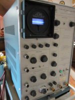
The crt is a unique blue shade and super crisp.
Those scopes exclusively used film cameras to capture the image and magnify it.
Is this an advantage? A common cathode tube can never get "out of balance" emission-wise, simply because there is only one cathode. So as the tube ages both halves will always remain in their original emission proportions.
A buddy of mine has a few Tek 519s. The crt is a unique blue shade and super crisp.
The lab I worked in had a TEK 545 with the fast blue screen. We needed something to record pulses with nS rise times, so the way in was direct to the CRT vertical plates. The vertical sensitivity was a problem. The fix was using a mercury relay, discharging a transmission line into the test object. That way the response was OK, all recorded on the TEK camera running Polaroid ASA 10000 film. The delay was provided by the TEK blue suitcase delay line. That all pre 1960.🙂 But that scope was hard on the eyes for much else.🙁
Last edited:
I used a dual tetrode ГУ-17 in my Constellation-T amp, as a LTP driver. It is a Soviet copy of QQE03/12 tube. It was used in UHF power amplification stages. The same construction as 6J6, but more powerful. There are even more powerful UHF tubes of a similar construction.
However, you can't match halves if they are in the same bulb, so I had to add a bias balancing pot.
However, you can't match halves if they are in the same bulb, so I had to add a bias balancing pot.
Windcrest77,
Please expand and/or clarify your question of Post # 65.
What earlier Post # does it refer too?
Please expand and/or clarify your question of Post # 65.
What earlier Post # does it refer too?
A common cathode tube can never get "out of balance" emission-wise, simply because there is only one cathode.
Beside also not understanding where your posting exactly refers to, your firm statement only holds if the surface of the cathode ages/deteriorates at even speed/rate. Maybe they (mostly) do, but I wouldn't know.
Windcrest77,
Please expand and/or clarify your question of Post # 65.
What earlier Post # does it refer too?
Configured as push pull for the earlier RF discussion about short leads and all in the tube. I would think a tube with two separate cathodes, at high frequency push pull, would play havoc if the two cathodes aged differently over time. One cathode seems to eliminate both that problem and overall less wire in the tube.
Here is a link to a very good paper on the history & progress of HF scopes. They mention sampling plug-ins for the HP 140 Series, I don't recall ever hearing of those at all, altho I sold many of the 140 series. And also Lumatron, they were in some labs but I never saw one in my travels. We had a TEK N plug-in for the 540 scopes. The blue suitcase delay line in our lab had the GR 874 Hermaphrodite connectors. I think it could be ordered with Type N connectors as well.
https://citeseerx.ist.psu.edu/viewdoc/download?doi=10.1.1.471.2710&rep=rep1&type=pdf
All very much off topic, but interesting to several here I guess.🙂
https://citeseerx.ist.psu.edu/viewdoc/download?doi=10.1.1.471.2710&rep=rep1&type=pdf
All very much off topic, but interesting to several here I guess.🙂
Configured as push pull for the earlier RF discussion about short leads and all in the tube. I would think a tube with two separate cathodes, at high frequency push pull, would play havoc if the two cathodes aged differently over time. One cathode seems to eliminate both that problem and overall less wire in the tube.
Better RF behaviour in push-pull operation (which as far as I know has mostly to do with the inductances of cathode leads) by using one shared cathode has been described often. But I keep having my doubts over the second part of your statement.
I think it's safe to presume that the pre-treated cathodes used for the construction of a series of double triodes with seperate cathodes, come from a same batch. Looking at the three factors which according to the authors of this book are decisive in determining the life of an oxide cathode, I still don't see why two seperate cathodes inside one tube, operating under the same conditions (which is the case with push-pull operation) would age/deteriorate differently than one shared cathode.
The Oxide Coated Cathode (G. Hermann, S. Wagener) 1951 (Volume II) : Free Download, Borrow, and Streaming : Internet Archive
And if cathode surfaces can't be produced controlled enough when producing a batch of pre-treated cathodes, than I don't see why these production differences would be of importance when looking at the surfaces of seperate cathodes, but would be of no importance when looking at the surface of a single cathode (localized aging/deterioration).
All this certainly doesn't prove that your statement is false, but (atleast to me) there seems to be some room for doubt.
All this certainly doesn't prove that your statement is false, but (atleast to me) there seems to be some room for doubt.
Interesting though. I think in a push pull circuit where both triodes are doing the same function, at the same DC operating points, upon the same AC signal, same plate loads and voltage... Separated cathodes are unlikely to become unbalanced in emission. But if the two triodes were doing dissimilar functions with different operating points the cathodes may age in unbalanced trajectories over time?Which doesn't apply here anyway.
I think so. Based on the findings in the book the aging/deterioration could very well be different when the two sections have been operating differently for some time. The question remains wether this effect is about the same for double triodes with seperate cathodes and double triodes with a common cathode.
I tested a lot of tubes some years ago. Among them were many double triodes with separate cathodes but just a few double triodes with a common cathode. I should have kept record of these kind of differences, but at the time I just binned a double triode as soon as one of the sections was duf. If I would have kept record, I still couldn't know how a particular double triode was used in the past. But it would have been a start. If there would hardly be double triodes in which the sections tested differently, it could be a clue. I just can't remember if I ever noticed something like that.
Maybe other forum members did notice something relevant when testing used tubes?
A couple of tubes to look at are the 829B and 832A.
Intended for RF Push Pull.
Separate Cathodes, but a common internal connection.
The same goes for the common internally connected screen grids.
The Beam Formers are internally connected to the cathode (need to see a tube to see if those connections are to each respective cathode, or just a common connection from Beam Former common to cathode common).
And there is an internal capacitor bypassing the screen to the cathode
(aparently from the common screen connection to the common cathode connection).
Then, there is the 'dual sided' 5894 with only one cathode, only one screen, and only one Beam Former. So there is no need for "internal" connections of those elements, it is intrinsic in the metalwork.
Only the control grids and only the plates are separate metalwork.
A question I have for all these tubes when used in push pull service is how equal are the quiescent currents of the two halves?
If they are not equal, will the cathodes deteriorate at different rates?
Last edited:
One can take this single cathode / dual tube idea to a further extreme.
Beam deflection tubes, such as 6JH8, have a single cathode forming a single electron beam. Two deflection electrodes allow the beam to be deflected linearly between two output plates. The tubes are equivalent to an adjustable CCS tail, with two triodes (LTP like) above it. Gain is low (Mu 6 for differential inputs) but can be increased greatly by a dual cascode stage above it. Almost the ideal phase splitter. They do require magnetic shielding and initial demagnetization however.
(https://frank.pocnet.net/sheets/093/6/6JH8.pdf)
Attachments
Very interesting! Do you have any examples or schematics for the PI application that you mentioned? For which use has this tube basically been designed?
Best regards!
Best regards!
One thing to remember is that the top stage of a cascode circuit is the very high output impedance.
The gain is high if the load is high impedance, but the gain is low if the load is low impedance.
Using a triode for the top stage of the cascode, the effective rp will be many times higher than that of the same triode rp in a single tube common cathode amp that uses a bypassed self bias resistor.
A load that varies widely versus frequency is probably not a good application for a cascode circuit.
From the data sheet for 6JH8, its obvious they were designed for TV color demodulating applications.
But I have seen schematics where this or similar BDT tubes (6ME8 uses deflectors at +75V, 6JH8 and others at 0V, 6AR8 similar, 6HW8, 7360 ) have been used for a voltage controlled attenuator (remote volume control). They can be used in pairs for generating or detecting SSB (single sideband, Ham radio), synchronous detectors, and also for doing analog multiplication (and division using a feedback loop). The 6JH8 is low distortion, 6ME8 has rounded saturation.
A "poor man's" version of these tubes (back then for TV) is the 6LE8. (I have seen 6JH8, 6ME8 and 6LE8 for cheap over the last 10 years)
For phase inverting I might use the unused deflector for Global N Fdbk, or one could try putting an R attenuator from one of the outputs back to the unused deflector. That should double the gain (pos. unity Fdbk)
Last edited:
A couple of tubes to look at are the 829B and 832A.
A circuit using a PP 832 did appear in DIY not long ago. Don't recall whether it was built or someones idea.
Around 1955 I built a PP 815 amp. Driven by a Triode connect 6F6 thru a Hammond 447 IT. It was soon pulled apart to build something else. Don't think it would test well on the bench today.😀 Still have an 815 in my stash, gave away a couple of them a while ago.
- Home
- Amplifiers
- Tubes / Valves
- 6J6 and it's history