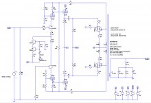
A friend of mine will gift me a hand-built Hi-Fi without tubes, but I all of of them already. The schematic is in attachment, the only variation is that EL34s run with 43% UL taps instead of pure pentode (so of course the choke will work on the PI and driver only).
It is around 15 years old, and built based on this article, with some variations:
PP2010 - Hi-End Push Pull Amplifier
First of all I have one question: layout is same for both monoblocks (they are not mirrored), wiring is same, but whilst one is perfect, the other one needed a 50 kHz lowpass on the PI because of some autooscillations out of the audio band. Can it be due to some differences on the parameters of the output transformers?
Then I would like to ask you if you agree on some mod to be done this winter, after a long period listening to it as is:
The first one is to move the coupling caps before the 12AT7, to apply the bias to theirs grids and DC couple them to the EL34s and to be able to drive them into AB2 squeezing a bit more watts.
To do so I will rectify full bridge the 40-0-40V winding and the 12AT7 will be connected to that negative rail (around -112V) through the resistors (that could become a CCS indeed), while anode will be kept positive of course.
The other one is to apply shunt feedback to the EL34s, that in this case I would apply by connecting the plates of the EL34s and the 12AX7 with a resistor (I guess the value will be around 1 to 2.2 MOhm). Then I'll try it with and without GNFB.
If you see something better that can be done to it, I'll be pleased to try.
Thank you all in advance.
Attachments
The EL 34 power pentode wasn't exactly designed for class AB2 operation. If you draw an appropriate loadline into the plate curves set, you'll see whether AB2 makes sense at all with them, 'cause the loadline may cross the leftmost curve at some still negative grid level.
Best regards!
Best regards!
Thanks as usual for your prompt reply, Kay.
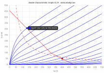
The reason why I asked about AB2 with EL34s, is that compared to the attached schematic of pure pentode, the amp is now working with 43%v UL taps.
Based on this document: http://www.oestex.com/tubes/Rudolf Moers - Appendices.pdf
EL34s in pentode mode can bring the anodes down to 30V being still in AB1, but with 43%v taps they can go down to around 150V only (see page 17). So I asked about AB2, in order to bring their anodes down a bit more.
What do you think?
Well, if the control grids permit it, class AB2, hence grid current, appears to work with UL configurations shown at that page.
Best regards!
Best regards!
Thanks again Kay,
indeed seems impossible to find Wg1 for EL34, and the reason could just be what you just said: it was optimized to make AB2 useless in pentode mode. I will pose the question on the BH34 thread: over there with all those people driving EL34s with powerdrive, there will be someone who got some first-hand information.
indeed seems impossible to find Wg1 for EL34, and the reason could just be what you just said: it was optimized to make AB2 useless in pentode mode. I will pose the question on the BH34 thread: over there with all those people driving EL34s with powerdrive, there will be someone who got some first-hand information.
I've found an easy improvement looking at different tube's curves and characteristics: substitute the EL34s with 6550s.
PT will supply the same power:
- heaters will pass from 1.5 to 1.6 A
- max plate current is already foreseen for 3.5 kRaa
- idle current raises from 2x 50 mA to 2x 85 mA
- Class AB1 power is higher (52 vs 41 Wrms)
- Class A is higher as well (13 vs 4 Wrms)
- g1 at idle goes from -34 to -39 Vdc, not a big change and easily manageable by the PI and driver.
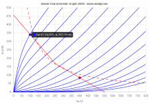
In attachment the curves and the loadlines.
PT will supply the same power:
- heaters will pass from 1.5 to 1.6 A
- max plate current is already foreseen for 3.5 kRaa
- idle current raises from 2x 50 mA to 2x 85 mA
- Class AB1 power is higher (52 vs 41 Wrms)
- Class A is higher as well (13 vs 4 Wrms)
- g1 at idle goes from -34 to -39 Vdc, not a big change and easily manageable by the PI and driver.
In attachment the curves and the loadlines.
Attachments
Some guidelines to chose the tube (Tungsol Reissue) and grid/screen stoppers here:
Maximum Plate/Screen Voltage 6550 in UL
Aronov LS9100 - any info ???
Maximum Plate/Screen Voltage 6550 in UL
Aronov LS9100 - any info ???
Regarding the instability on one monoblock, I bought a job lot of 12AT7WA last year (actually CV4024) and I tested a bunch and only 1 in 10 were reasonably matched for gm of the triodes, within 5%. The design is very sensitive to that driver tube being balanced.
Also, 1uF seems very large for a coupling capacitor?
Also, 1uF seems very large for a coupling capacitor?
zintolo,
EL34 Yes.
The EL34 works with fixed bias and 500k g1 resistance.
The amp in post # 1 has more than 220k.
6550 No.
The 6550 works with fixed bias and 50k absolute maximum g1 resistor!
Not working without changing the load on the Driver tubes;
The driver tubes have to be re-designed to drive 50k instead of 220k.
Make 1 little change, and you have to make at least 3 more changes to make it work.
Last edited:
Thanks OldHector, great information and I will check it.Regarding the instability on one monoblock, the design is very sensitive to that driver tube being balanced.
Luckily they are two Solen Fast mounted on the back of the pcb, so easily accessible from the bottom. I will chek other values as well.Also, 1uF seems very large for a coupling capacitor?
6550 No.
The 6550 works with fixed bias and 50k absolute maximum g1 resistor!
Not working without changing the load on the Driver tubes;
The driver tubes have to be re-designed to drive 50k instead of 220k.
Thanks 6A3sUMMER, so one option could be dc couple the driver with 33 kOhm, moving the bias on the grid of the 12AT7 and so full-bridge rectify the 40-0-40V winding to supply the driver with a reasonable low voltage?
6A3sUMMER, actually the grids of the EL34 see:
4k7 grid stopper + 220k grid lead + 47k||(22k/2 + 22k/4) = 224k7 + 47k||16.5k = 224k7 + 12k2 = 237 kOhm
So with 1 kOhm as grid stopper and 100 Ohm screen stopper, the grid leak must be lower than: 50 kOhm - 1 kOhm - 12.2 kOhm = 36.8 kOhm.
Closest lower value is 33 kOhm.
How do I need to modify the 12AT7 to be able to swing 80Vpp on that redcued load?
Will a CCS instead of the 33 kOhm cathode resistor be enough, or it is needed to dc couple the driver?
Thanks in advance and sorry for my basic questions.
How do I need to modify the 12AT7 to be able to swing 80Vpp on that redcued load?
Isn't this a similar scenario to the Tubelab SSE, and Powerdrive?
Tubelab SSE schematic
The Tubelab has a 12AT7 plate driving an extremely large impedance CCS and the following stage's 220K grid resistor.
When you change the following stages grid resistor to 50k, the 12AT7 voltage gain will be reduced, and the distortion will go up.
But it still May be able to drive +/- 40V (it has to do with the self bias voltage of the 12AT7, the quiescent plate voltage, and the B+ voltage at the top of the CCS). You might have to lower the resistor in the B+ that sets the B+ at the top of the CCS.
Reducing the 10k resistor that is in series, might require the 900V IXYS part to be used, instead of the 400V IXYS part.
I do not see any B+ voltage measurements in that schematic, and no B+ secondary voltage ratings.
Last edited:
I've done some simulations on LTSpice.
I've used 6550s and supplied the 12AT7 with +360V and -56V as per the original design.
Used 33 kOhm 6550 grid leak instead of 220 kOhm, then applied shunt feedback to the PI, without global negative feedback.
PI current lowered to 650 uA on each side.
This is the result:
So I have 50 Wrms with 1.5% THD that is mainly 3rd harmonic.
I've used 6550s and supplied the 12AT7 with +360V and -56V as per the original design.
Used 33 kOhm 6550 grid leak instead of 220 kOhm, then applied shunt feedback to the PI, without global negative feedback.
PI current lowered to 650 uA on each side.
This is the result:
Code:
Harmonic	Frequency	 Fourier 	Normalized	 Phase  	Normalized
 Number 	  [Hz]   	Component	 Component	[degree]	Phase [deg]
    1   	1.000e+03	2.757e+01	1.000e+00	   -1.29°	    0.00°
    2   	2.000e+03	9.405e-03	3.412e-04	  176.11°	  177.39°
    3   	3.000e+03	3.658e-01	1.327e-02	   30.19°	   31.48°
    4   	4.000e+03	5.381e-03	1.952e-04	   59.74°	   61.02°
    5   	5.000e+03	1.468e-02	5.324e-04	  -44.80°	  -43.52°
    6   	6.000e+03	6.905e-03	2.505e-04	  -72.94°	  -71.65°
    7   	7.000e+03	1.693e-01	6.143e-03	  -63.36°	  -62.08°
    8   	8.000e+03	1.876e-03	6.806e-05	 -142.18°	 -140.89°
    9   	9.000e+03	1.017e-01	3.688e-03	 -178.78°	 -177.49°
Total Harmonic Distortion: 1.509687%(1.806634%)
So I have 50 Wrms with 1.5% THD that is mainly 3rd harmonic.
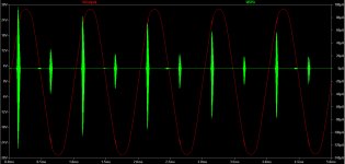
So, this is the schematic I'm simulating.
I also attach a simulation with some spikes of oscillations. Can anyone explain me why they are there? Simulation error or real instability?
Thank you all in advance.
Roberto
I also attach a simulation with some spikes of oscillations. Can anyone explain me why they are there? Simulation error or real instability?
Thank you all in advance.
Roberto
Attachments
I've found four matched EL34s in one box, I will use them so I decided to modify it as follows:
- connect 40%UL taps
- wire the secondary 0-4-8-16 Ohm as follows: ground the 4 Ohm tap, connect the 0 and 16 to the cathodes of the EL34s as cathode feedback, and connect my 8 Ohm speakers between 4 and 16 Ohm taps, in order to have 7 kOhm Raa instead of 3.5
- connect the grid of the 12ax7 with UL connection ( The Tube CAD Journal,Ultra-Linear Output Stages ) with 100k 56k divider
These are the results at approximately 35 Wrms without global feedback (jfet model could not be accurate:
Code:
Harmonic	Frequency	 Fourier 	Normalized	 Phase  	Normalized
 Number 	  [Hz]   	Component	 Component	[degree]	Phase [deg]
    1   	1.000e+03	2.318e+01	1.000e+00	    0.32°	    0.00°
    2   	2.000e+03	7.657e-03	3.304e-04	  109.11°	  108.79°
    3   	3.000e+03	1.518e-01	6.550e-03	  176.83°	  176.51°
    4   	4.000e+03	5.291e-04	2.283e-05	 -128.92°	 -129.24°
    5   	5.000e+03	8.081e-02	3.487e-03	 -177.65°	 -177.97°
    6   	6.000e+03	2.593e-03	1.119e-04	 -105.65°	 -105.97°
    7   	7.000e+03	6.208e-02	2.679e-03	   -0.38°	   -0.70°
    8   	8.000e+03	1.874e-03	8.087e-05	   96.16°	   95.84°
    9   	9.000e+03	3.308e-02	1.427e-03	  178.60°	  178.28°
Total Harmonic Distortion: 0.802540%(0.808006%)zintolo,
The 6550 control grid needs a 50k or less resistor to ground (or to the bottom of the cathode circuit that connects to ground.
In your case, that is the 1 Ohm cathode resistor.
Your simulation schematic in Post # 16 has 60k returning to the negative bias circuit.
So it is 60k plus what ever DC resistance the bias circuit is to ground.
That does not meet the criteria for the 6550 control grid.
It may work, it may not work.
Your mileage may vary.
Depends on the Plate voltage, screen voltage, plate current, screen current, and the manufacturer and how tolerant the tube is of using too large of a g1 to ground resistance.
I am quite sure that no simulation software ever takes into account the maximum g1 resistance requirement.
If so, it should have "flagged" you on the error you made versus the tube maximum g1 resistor spec.
All of the above is just my opinion that has personally had an original Tungsol 6550 Run Away and Red Plate.
Last edited:
Thank you 6A3sUMMER,
I simulated the EL34 considering 100 kOhm to ground, just to be on the safe side. I also considered around 40 mA for each EL34, remembering your warnings about run-away of tubes. This way it should be more than safe.
I simulated the EL34 considering 100 kOhm to ground, just to be on the safe side. I also considered around 40 mA for each EL34, remembering your warnings about run-away of tubes. This way it should be more than safe.
I see that you have output tube plate to the 12AX7 plate and grid.
Positive feedback, and negative feedback.
Also, the 12AX7 plate resistance, rp, is extremely high, because it is in Cascode Mode with the JFET.
Then there is the phase shift of the 12AX7 versus frequency, 100k to the grid, and 10k to ground; the cascode has very high gain, lots of Miller Effect capacitance, and at high frequencies it may be an issue.
Then, the only drive to the bottom 12AX7's grid is from the plate of the bottom output tube plate. But there is leakage reactance from 1/2 of the primary to the other 1/2 of the primary. That creates phase shift.
Could all those phase shifts be what is causing the oscillation in the simulation?
- Home
- Amplifiers
- Tubes / Valves
- improvements on 12AX7 12AT7 EL34 schematic?