1uF will be to do with preventing motorboating/LF peak. One day I will measure some modern 6550's for g1 current at max power dissipation. Although 50k is on the data sheet a lot of schematic have 100k grid leak. The the current arrangement you will get some positive volts on the EL34 but you will also get blocking distortion. Certainly there is benefit in going up to +5v grid on 6550/KT88/EL34's. The miller effect will be needed to get the dominate pole so improving the HF handling will affect stability. This won't show up in LTspice without an accurate OPT model. Those spikes on simulation you do see on real amps - you may need to add a dominant pole.
Last edited:
I don't think you need to DC couple the driver. Even with AC coupling the grid will go above 0v - check on your simulation. The only problem it that will charge the DC coupling caps and make the bias more negative - you will see this too. Making the grid stoppers on the EL34 helps 4k7-10k.
Thank you, I will simulate that solution.
As the file cannot be attached due to its size, I'll report here the information.
OPT:
Raa: 3.5 kOhm (I know it's low, I will double it to 7 kOhm by connecting the 8 Ohm speaker to the 4 Ohm tap)
UL taps: 40.35%
Secondary: 0-4-8-16 Ohm
Core: EI 80x96x50 mm (column 32)
Material: M6
Width: 0.35 mm
Nominal current: 90 mA
Primary Inductance: 27.85 H
Nominal induction: 0.5 Wb/m2
Current density: 2-2.5 A/mm2
Primary: 694 + 694 turns with 0.224 mm wire
Secondary: 3x 52 turns with 0.71 mm wire + 21 turns with 1 mm wire + 30 turns with 0.85 mm wire
Total 11 sections
Insulation between sections: 3 layers of Dacron Mylar Dacron of 0.1 mm
PT:
Primary:
0-230V (595 turns with 0.45 mm wire)
Secondary:
0-300V 220mA (830 turns with 0.315 mm wire)
0-6.3V 5A (17 turns with 1.5 mm wire)
40-0-40V 100mA (110+110 turns with 0.2 mm wire)
Core: EI 80x96x50 mm (column 32)
Material: M330
Width: 0.5 mm
Losses: 1.35W at 1Wb/m2
Induction: 1.09 Wb/m2
Current density: 2.8 A/mm2
Nominal power: 106 W
Thanks, this fit what I usually have in my guitar amps: 2k2 for 6L6GC and 5k6 for EL34.Making the grid stoppers on the EL34 helps 4k7-10k.
I'm calculating the -3 dB cut-off frequency of the ourput transformer and I have a question.
Basically that point is at the frequency where primary inductance has the same impedance of the primary impedance in parallel with the loading impedance plus primary resistance.
Very easy for Class A (RDH4 page 211 and following have an example):
Being the internal resistance of the EL34 in triode mode 910 Ohm as per Mullard datasheet, and 15 kOHm in pentode mode, I expect it to be around 2 kOhm with 40% distributed load plus cathode feedback.
So let's say 50 Ohm primary resistance, in class A when both tubes conduct it will be:
RA = 4050 x 7000 / (4050 + 7000) = 2565 Ohm
So with 28 H of primary inductance the low -3 dB point will be at 14 Hz and -1 dB point at 28 Hz.
But what happens for push-pull designs in class AB, when one side is conducting while the other one not?
Do I need to split the primary in two parts, one paralleled to the tube and the other one paralleled to an almost open contact?
So one side is 1750 || 2025 = 940 Ohm
and the other side simply 1750 \\ inf = 1750 Ohm?
So totally is 2690 Ohm? Not so far from the Class A case?
Thank you in advance
zintolo,
I was not sure of the parameters of your transformer.
So I will give an example transformer to illustrate the principal:
Push Pull Transformer:
6k plate to plate
100 Henrys plate to plate
That is 1.5k plate to center tap (Z is proportional to root of turns)
That is 25 Henrys plate to center tap (Inductance is proportional to root of turns)
In class A, each tube works together with the other tube.
Effectively, the tubes together see 3k load and 50 Henry.
(relatively easy load)
In class AB, with one tube off . . .
The tube that is on sees 1.5k load and 25 Henry.
(relatively hard load)
This causes a shortening of gain and output voltage when in AB.
But that shortening is symmetrical and is dominant 3rd Harmonic Distortion.
A few ways to improve this is to:
1. Use plate resistances, rp, that is much lower than the 1/2 winding Z and 1/2 winding Inductance.
2.Use negative feedback (either from output transformer primary, or from output transformer secondary).
Note: I prefer the negative feedback to come from the primary. Slightly less gain / phase problems (less group delay).
3. Keep the amplifier in class A (do not use enough drive to take the amp to class AB).
Last edited:
Thanks 6A3sUMMER,
So in my case I have 28 Henry and 7 kOhm Raa.
Internal resistance of the EL34 with UL+CFB I expect to be not less than 2 kOhm (being 910 Ohm in triode connection).
So in class A I have 4k||7k = 2k5
Thrn with 28 H I have a -3 dB point at 14 Hz and -1 dB point at 28 Hz.
In class AB I have 2k||1k75 = 933
So with 7 H I have a -3 dB point at 21 Hz and -1 dB point at 42 Hz.
Is it correct?
Thank you in advance
Roberto
So, today I had finally time to perform some tests and modify the amp.
The amp as is had a nice midrange at low volume, but not so much gain and at high volume the midrange became harsh and too much prominent. As anticipated, the load was too low (3.5 kOhm Raa).
Then I connected the 8 Ohm speaker to the 4 Ohm output and the story absolutely changed: a more gentle saturation, more linearity, less "character" to the sound and it became pleasant to hear music at higher volume.
Next step: ground the 4 Ohm output, and connect the cathodes of the power tubes to the 0 and 16 Ohm secondary: I got more low end, more high end, more control, "faster notes" and more detail to every passage even at high volumes.
I'm quite happy with it with many different music styles, from Mozart to Rage Against The Machine, to Police, to Corduroy to some jazz.
Next step will be to work on the gnfb to have a reasonable amount of it, as now the results are not bad at all even without gnfb, whilst the orignal amount of gnfb is way too much.
I will also try some shunt feedback to it.
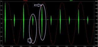
From the snapshot, I figured that the higher frequencies are spurring out of the output waveform, very similar to ringing (not steady oscillation), as it increased with output level. You can see better with square wave, and must you need to experiment with value of Zobel circuit in the output, the frequency of spur is quite high so it needs to be lowered if not eliminated. Since there is no NFB so you can rule it out as the cause.So, this is the schematic I'm simulating.
I also attach a simulation with some spikes of oscillations. Can anyone explain me why they are there? Simulation error or real instability?
Thank you all in advance.
Roberto
Attachments
One of easier way is by virtual inspection: the correct values will change the frequency of ringing, not the just the amplitude. I have pdf document for the complete procedure, but try this.
Here is testing square wave where f is frequency of interest:
Enter this to sig gen you get the square wave:
PULSE(0 0.5 0 1u 1u {1/2/f} {1/f})
Completed output transformer measurements
So you can measure the inter winding capacitance and calculate the K factor indirectly from leakage inductance. Leakage inductance is measured when the secondary is shorted by low resistance wire.
Last edited:
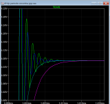
.step param Cz list 0.05n 0.1n 0.5n 1n 1.5n
You mention 1n and 1k zobel with 1k square wave, so here is the result of 1k with above caps in plate of my amp sim, for sharing what I meant. Pink curve is 1.5n is over specified and others under specified values.
You mention 1n and 1k zobel with 1k square wave, so here is the result of 1k with above caps in plate of my amp sim, for sharing what I meant. Pink curve is 1.5n is over specified and others under specified values.
Attachments
The simulation is only as accurate as the models you have. For example the transformer could include some primary capacitance, and the leakage inductance may be measured at a very different frequency to the oscillation. Even with this its only an approximate model. However it does give a good indication that there is a potential problem.
Try increasing the screen resistors a bit this may help.
Try increasing the screen resistors a bit this may help.
Last edited:
Thanks Koonw! I will try it.
Thank baudoin0, yesI know models have their limits, especially when out of linear conditions.
Another suggestion I've got is to make the PI work with higher currents (around 2 x 1.5 mA) to improve the working point of the bottom fet. A lower load for the 12ax7 will be needed. What is above my knowledge is how to determine the curves of each side of the PI, so to determine how to make it better work.
In the tail of PI it's a constant current sink is biased by D1, D2 which is fixed, but I think you still can vary R11 2k emitter resistor to change the current. So if the original is 1mA, increased another 0.5mA will drop the plate voltage by 11V, as DC, whether affects the next stage or not. 1mA is fine with 12AX7. Since the 6550 is biased at -38V, the 12AT7 should see at least 38V at it's grid, at 80v Ik=4.6mA, 1.25W that still within limit of 3W.
Last edited:
Thanks again. I've found this page where a technician explains the modifications he has applied to the original design:
PP2010 - Hi-End Push Pull Amplifier - Audio Design Guide | SB-LAB di Bianchini Stefano
This is the corrected schematic, but some values shown on the image differs from what written on the text (sorry, it's only in Italian).
https://www.sb-lab.eu/wp-content/uploads/2016/02/pp2010-upgrade-2020.png
PP2010 - Hi-End Push Pull Amplifier - Audio Design Guide | SB-LAB di Bianchini Stefano
This is the corrected schematic, but some values shown on the image differs from what written on the text (sorry, it's only in Italian).
https://www.sb-lab.eu/wp-content/uploads/2016/02/pp2010-upgrade-2020.png
- Home
- Amplifiers
- Tubes / Valves
- improvements on 12AX7 12AT7 EL34 schematic?