Diabolical Artificer,
In reference to your to Post # 13:
Heathkit W5M:
The 300 Ohm pot Does adjust DC current balance.
If there is not enough range of adjustment, it means your output tubes are too far from being anywhere near to being matched.
About $5 additional during your purchase gets your pair of tubes matched . . .
a very smart investment.
Do not replace only one tube of a push pull pair.
Good hobbies are not cheap, but they can be economical.
Ketje,
On the W5M, if the DC current balance pot wiper lifts, there is no DC path to ground.
That is a problem.
The output tubes will be at zero bias, and the cathodes will "head toward" the plates.
The cathode voltages will rise, and the 50V electrolytic bypass caps will be destroyed.
That is why I recommended two 1k resistors to ground, with the other ends connecting to the ends of the 300 Ohm pot.
Any reasonably matched pair of KT66 tubes will still be able to be DC current balanced.
I made a mistake, I overlooked one important point:
Adding two 1k resistors in the path to ground will raise the quiescent current of the KT66 tubes.
The fix for that is to change the series common 330 Ohm self bias resistor to 365 Ohms
(or just add 35 Ohms in series with the 330 Ohm resistor that is already there).
Changing one thing often requires 3 more changes to make it work right.
Pretty much the case here.
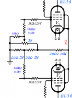
Here are two methods I've used to provide bias and balance adjustment for push pull output stages. The first is an AB1 stage, the second is a class A stage. Adjust component values to suit the range adjustment you need.
These methods offer fail safe operation in the event of wiper(s) disconnecting from track.
These methods offer fail safe operation in the event of wiper(s) disconnecting from track.
Attachments
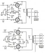
Here are two methods I've used to provide bias and balance adjustment for push pull output stages. The first is an AB1 stage, the second is a class A stage. Adjust component values to suit the range adjustment you need.
These methods offer fail safe operation in the event of wiper(s) disconnecting from track.
Thanks, your first example is exactly what I had in mind and it's good to see more application of it. On a separate topic, would that first schema be a "mixed" or "adjustable cathode" bias? I've heard of a few cases that's used, I don't think this amp will be the spot I try it out but would be interested to read more if you've got a resource (or anecdotes) on it.
The first one (top in the previous diagram) is a fully fixed bias topology, but it's adjustable.
The second one (bottom in the previous diagram) is a cathode bias topology overall, but it siphons voltage from the cathode and applies it to the grid to allow for some adjustability. The idea is not new, in fact I adapted it to work with my amp after studying the HK A500 circuit.
The second one (bottom in the previous diagram) is a cathode bias topology overall, but it siphons voltage from the cathode and applies it to the grid to allow for some adjustability. The idea is not new, in fact I adapted it to work with my amp after studying the HK A500 circuit.
The first one (top in the previous diagram) is a fully fixed bias topology, but it's adjustable.
The second one (bottom in the previous diagram) is a cathode bias topology overall, but it siphons voltage from the cathode and applies it to the grid to allow for some adjustability. The idea is not new, in fact I adapted it to work with my amp after studying the HK A500 circuit.
Thanks for the clarification. I was wondering if the bias test resistors would have any appreciable affect on the bias point, which is why i asked. The voltages I'd expect are in the range of tenths given those r-values but without asking I didn't feel comfortable just hand-waving it away.
Right, 10R at ~30 mA is 0.3V, so for all intents and purposes is negligible. The only purpose for those 10R resistors is for cathode current measurement given the adjustability of the circuit.
The 10R resistors do affect an AB1 stage ever so slightly--at full power a minuscule amount of power is lost, and distortion is ever so incrementally higher--but again negligible in my opinion, and well worth the trade off of having visibility into the DC conditions of the stage (bias and balance).
The 10R resistors do affect an AB1 stage ever so slightly--at full power a minuscule amount of power is lost, and distortion is ever so incrementally higher--but again negligible in my opinion, and well worth the trade off of having visibility into the DC conditions of the stage (bias and balance).
Last edited:
kward,
I believe your second diagram is not strictly class A.
The 130 Ohm resistor is not a true current source.
So you can start with a total quiescent current, and then you can draw more than the quiescent current at the time when signal dictates that one (or the other) tube cuts off, and the remaining tube draws more than the original total quiescent current.
During the time when the voltage across 130 Ohms rises above the quiescent voltage, the 10uF bias bypass caps keep the bias voltage at the 100k grid resistors at a constant voltage.
The signal is probably still clean and useful, but I believe it is in Class AB at that time.
If you have designed the driver to limit its voltage swing, then the amp is still Class A.
But a larger driver voltage swing puts that output stage into Class AB.
Right?
Now if the 130 Ohms was replaced with a true current sink, the current could never be higher than the quiescent value.
That would mean the output stage was always in Class A, right up to the time that the amplifier was very badly distorted (clipping).
The idea is that for all reasonably linear power levels, the amp with the constant current sink is always in Class A.
Last edited:
6A3,
The stage is biased so both tubes conduct a full 360 degrees up through g1 = 0V. So perhaps I should have said class A1. Certainly the conditions you describe would occur in A2.
Now in reality there is a small amount of fluctuation in current through the cathode resistor at near class A1 max power because of small differences in tube matching. A current source or just a bypass cap would address that, though. I ended up adding a cathode bypass cap in the final design for that reason.
kward,
Class A on 6L6GC tubes.
I did not realize that bias voltage would do that.
I should have noticed the 12.6V bias cathode-to-g1.
Perhaps I will try looking at that circuit on a set of curves, with a load line.
What was the plate to plate primary impedance?
Class A on 6L6GC tubes.
I did not realize that bias voltage would do that.
I should have noticed the 12.6V bias cathode-to-g1.
Perhaps I will try looking at that circuit on a set of curves, with a load line.
What was the plate to plate primary impedance?
Last edited:
6A3,
The output transformers used on that particular class A amp were pulled from a derelict Fisher TA-800. They measured 6.2k, end to end.
Max power output was 12 watts per channel, both channels driven.
Frequency response was to 35 KHz at -1 dB (with 14 dB global feedback).
Power bandwidth, both channels driven was 30 Hz to 35 KHz +0/-1 dB
THD at 12 watts output, both channels driven was 30Hz: 0.72%, 1KHz: 0.16%, 20 KHz: 0.7%
Excellent performance! But does the amp sound better than the same topology and tube compliment in an AB1 design? Not in my opinion. It was an experiment in designing/buiding a class A PP amp.
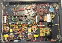
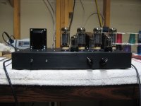
Amp shown below (7581A output tubes shown)
The output transformers used on that particular class A amp were pulled from a derelict Fisher TA-800. They measured 6.2k, end to end.
Max power output was 12 watts per channel, both channels driven.
Frequency response was to 35 KHz at -1 dB (with 14 dB global feedback).
Power bandwidth, both channels driven was 30 Hz to 35 KHz +0/-1 dB
THD at 12 watts output, both channels driven was 30Hz: 0.72%, 1KHz: 0.16%, 20 KHz: 0.7%
Excellent performance! But does the amp sound better than the same topology and tube compliment in an AB1 design? Not in my opinion. It was an experiment in designing/buiding a class A PP amp.
Amp shown below (7581A output tubes shown)
Attachments
Last edited:
kward,
Thanks for your answers, and for the pictures.
Experimental amplifiers are nice (except the ones that blow up).
I once mis-wired a 7591 amp (used the 6L6 pinout, not thinking).
Fortunately, as I brought the amp up, I immediately saw the large current, so quickly turned the amp off.
Wiring corrected, and all was OK (nothing got "hurt").
One issue I've come across is 10r sense resistors going high, I'm not talking about low quality, low wattage types either. it's happened to two types of 2w and 5w Vishay resistors, big 5w Ohmite and several others. I used Welwyn W20 WW's in the end.
To be fair most of these failures happened in the tweaking stage,where wires are not properly dressed or fixed etc, but I've been surprised a few times when instead of reading 0.3v or whatever, to read 100v across the cathode sense R!
Until the other day I wasn't 100% certain how this happened, only that HV or high current transients were involved. Whilst testing an amp design the other day I saw a spark out of the corner of my eye, then the amp shut down, thanks to the protection circuit. In a PPP amp, one sides g2 bus had shorted to the g1 bus briefly.
On inspection both 10r cathode sense R's read over 1m, so choice of sense R worth giving some thought to, it will only take a slip with a cable, cap dying or other failure to bias your OP valves into orbit.
Andy.
Last edited:
Audio Beam Power Tubes and Audio Pentode tubes are usually not designed to have the g2 power supply connected to g1. That was a very bad thing that happened to your amplifier.
Changing the cathode sense resistor to a different ohmic value will not fix this kind of problem.
A couple of things that can burn out those cathode sense resistors:
1. Using an adjustable fixed bias supply, that does not have a resistor(s) to keep some negative voltage on g1 when a pot wiper lifts (even for a brief time during turning a pot to set the bias adjustment).
2. Using g1 return resistance that is higher than the tube specification.
I was given an EL34 amplifier, someone had replaced the EL34s with 6550s.
The amplifier used adjustable fixed bias.
The EL34 can have 500k g1 resistor (the amp had 470k).
The 6550 can have 50k g1 resistor (470k is over 9 times the max spec).
Guess what?
The 10 Ohm cathode sense resistors were blown.
It's not nice to fool Mother Nature!
- Status
- This old topic is closed. If you want to reopen this topic, contact a moderator using the "Report Post" button.
- Home
- Amplifiers
- Tubes / Valves
- Push-Pull Bias Balancing