If has not become plain yet, a OPTx capable of these power levels is not going to be short on both leakage L, and capacitance. The Altec 16355 went about as far as you can go, and perhaps a few feet more than that, and at half the power level of this goal.
This is part of the reason for suggesting a single pair of finals. Go big enough. GU-81m comes to mind with its 150W Thoriated cathode, and 120W g2 dissipation rating. Two will be fine, and with a solid grid choke no heroics will be needed for a grid current-capable driver...B+ will need to be about 3/4 of a kV, and with that much plate dissipation you can stay Class A. And with only two grids, a smaller sweep tube can drive a plate-to-grid NFB circuit...which will make NFB issues due to a less than ideal OPTx much smaller.
Ultimately, I do think you're nuts for going there; get more efficient speakers, and divide up the spectrum and at least bi-amp...two sets of 80W, and a 30W for the very top end will do quite well...")
cheers,
Douglas
This is part of the reason for suggesting a single pair of finals. Go big enough. GU-81m comes to mind with its 150W Thoriated cathode, and 120W g2 dissipation rating. Two will be fine, and with a solid grid choke no heroics will be needed for a grid current-capable driver...B+ will need to be about 3/4 of a kV, and with that much plate dissipation you can stay Class A. And with only two grids, a smaller sweep tube can drive a plate-to-grid NFB circuit...which will make NFB issues due to a less than ideal OPTx much smaller.
Ultimately, I do think you're nuts for going there; get more efficient speakers, and divide up the spectrum and at least bi-amp...two sets of 80W, and a 30W for the very top end will do quite well...
cheers,
Douglas
It’s already hardware, not vaporware, and no exotic parts were required. There may be tweaks, and likely will have a balanced input added (degenerated 12AX7 and MJE340 CCS). Two independent amplifiers with 3 prong plugs is just an invitation for a ground loop otherwise. I have no shortage of efficient speakers (a shop full of PA gear), and the ones to be built for this system are no exception.
The subwoofer amplifier may be a bit more of a challenge - but it is at this point a science experiment and only in planning stages. I want to try an Antek 15T950 as an output transformer with a bunch of inexpensive sweeps driving it. One will get ordered along with the 2nd set for this amp. That trafo won’t be near as good as the Hammond, but could support 800 watts at 30 Hz without saturating. Will it have enough inductance? Is the capacitance too much? Only experimenting will tell.
The subwoofer amplifier may be a bit more of a challenge - but it is at this point a science experiment and only in planning stages. I want to try an Antek 15T950 as an output transformer with a bunch of inexpensive sweeps driving it. One will get ordered along with the 2nd set for this amp. That trafo won’t be near as good as the Hammond, but could support 800 watts at 30 Hz without saturating. Will it have enough inductance? Is the capacitance too much? Only experimenting will tell.
I am no expert here but I would imagine OPT's just scale. So if you need a bigger transformer then the turns ratio will be lower as your driving from a lower impedance. Anyway for a subwoofer HF frequency response is not an issue - you can rool your amp off at 1KHz making the NFB a doddle. You could balance with an input transformer.
There was a recent post on diyaudio which was using to two mains toroids as OPT's which may work for you bass amp. It was some clever arrangement which I think shared the output voltage - not sure. Mind the 15T950 is cheap.
There was a recent post on diyaudio which was using to two mains toroids as OPT's which may work for you bass amp. It was some clever arrangement which I think shared the output voltage - not sure. Mind the 15T950 is cheap.
Last edited:
I thought about that method - interleaving two dual-120v primaries to get a “480 volt capable” OPT. But I see a potential problem with that. In a normal toroid designed for 120/240 operation, the primary is bifilar wound with ordinary single-build magnet wire. They assume there will only be 120 volts between adjacent turns. If you interleave two and use it at full voltage, this will be exceeded. A dual 950v secondary (or primary) will have been designed to tolerate 950 volts between the two windings, either by using a really heavy build or using independent windings. This would be required even with a normal center tapped full wave, choke loaded rectifier. One would expect these transformers to be able to be used this way.
I didn’t do the power supply this way on the 6550 amp because I’m to cheap to buy a $300 choke when there is a way to do it without one. The other obvious way is with an SMPS, but the total cost of that would faaaar outweigh the 4 Anteks, and the supply would still be in development for another year, with exploded IGBTs along the way. This power level is not trivial or cheap with SMPS.
I didn’t do the power supply this way on the 6550 amp because I’m to cheap to buy a $300 choke when there is a way to do it without one. The other obvious way is with an SMPS, but the total cost of that would faaaar outweigh the 4 Anteks, and the supply would still be in development for another year, with exploded IGBTs along the way. This power level is not trivial or cheap with SMPS.
I thought about that method - interleaving two dual-120v primaries to get a “480 volt capable” OPT
I am making some PC boards for high power testing with 36LW6's. I really don't want to risk my irreplaceable Plitron OPT's until all of the exploding parts stuff is over, so I will try the interleaving trick with a pair of Antek 4TK400's that I have. That should get me a "1600 volt capable" OPT.
You’re more likely to be able to get away with interleaving the 400 volt “secondaries” as they should be well insulated from one another to support normal operation. If I understand correctly, you will be just paralleling all four 120V “primaries” on the speaker side, so regular bifilar with single build won’t be an issue. Pretty similar to just using an 8T800 - but of course using what you already have makes sense. And supposedly you get better HF response with two interleaved than with a single toroid that’s only really intended for mains frequency.
If I understand correctly, you will be just paralleling all four 120V “primaries” on the speaker side
Yes.
but of course using what you already have makes sense.
Yes, I have two of these and were not made as initially described when they first came out. They have since quietly disappeared from Antek's lineup. Both windings were identical (in phase) making the 70 volt taps useless for a +/- 100 volt supply. The 5 volt heater winding was next to, and often touching the 6.3 volt winding. This means that wire insulation is the only thing keeping B+ out of your heater circuit.
as they should be well insulated from one another to support normal operation.
Unfortunately, I'm not sure that's how the Anteks are wound. My experience with the 4TK400's lead me to believe that the two secondaries may be bifilar with only the wire coating for insulation.
A Dumm Blonde moment allowed me to let a room full of smoke out of an Antek 4T360, so I have been meaning to take it apart. Somehow it got mixed in with my transformer stash and I accidentally wound up using it again despite it's rather yellowish brown appearance......it works just fine running an 80 WPC tube amp. The secondaries are wired in parallel into a SS bridge, so a short between them would not be noticed. It was a backwards diode in the bridge and no fuse in the primary that let the smoke out.
And supposedly you get better HF response with two interleaved than with a single toroid that’s only really intended for mains frequency.
I have had hit or miss luck with using line (mains) transformers for OPT's ever since my childhood. Some work good, some suck no matter how you connect them. In my youth I would dig through the trash dump for old TV power transformers that had 3 heater windings. Wire all three in series for the speaker output and use the HV winding for a "primary." These were mostly guitar amps where response to 5 KHz was good enough.
About 10 years ago I found a bunch of thermal printers in the trash at a warehouse complex. All had toroidal power transformers, which I collected. There were two kinds, small and medium size, and at least two manufacturers for each part number. I remember that one manufacturer of the medium size unit worked beyond 20KHz in a P-P amp, while the other was unusable. Those went back to the dumpster.
Yes, I have two of these and were not made as initially described when they first came out. They have since quietly disappeared from Antek's lineup. Both windings were identical (in phase) making the 70 volt taps useless for a +/- 100 volt supply. The 5 volt heater winding was next to, and often touching the 6.3 volt winding. This means that wire insulation is the only thing keeping B+ out of your heater circuit.
I was wondering what happened to that model - was it the one tube trafo model that had no magnetic shield? I wanted to try that one by interleaving the 120 and 400 volt windings, and ADDING a 22 or so volt secondary in series with the 6.3V for the speaker. Now it’s gone.
The 70 volt taps are really only useful for a bias supply, where you capacitively couple off to a half wave rectifier (and return path for the DC). That limits the current you can useably draw. Or if you just need the next size down (70 volts less).
The auxiliary windings on their regular solid state models are just wound in with the main secondary. Not usually an issue if you’re using it for fans and a supervisor circuit.
I have had hit or miss luck with using line (mains) transformers for OPT's ever since my childhood. Some work good, some suck no matter how you connect them. In my youth I would dig through the trash dump for old TV power transformers that had 3 heater windings. Wire all three in series for the speaker output and use the HV winding for a "primary." These were mostly guitar amps where response to 5 KHz was good enough.
Toroids in general have low leakage reactance. That’s why we like them for solid state amps - they don’t drop like a stone under very heavy load. At least the big ones don’t. Equivalent VA EI units always drop more, a lot more, using cap input filters. I’ve seen quite a few projects in this forum using the 50 VA Antek models as OPTs. Here’s hoping the big ones just get better. Then that leaves the only real issue being a lack of DC tolerance. Wonder if a DC servo (like used for offset nulling in solid state amps) would be useful as a means of balancing out the DC shift effects of 2nd HD.
Off to order two more 4T430’s, a 2T300 and a 05T160. I’ve got another 6550 channel to build.
The 70 volt taps are really only useful for a bias supply,
In a usual Hammond power transformer there is a 70 volt tap on one side of the HV secondary. True, you can only draw a couple mA from these as they must be half wave rectified and any significant current draw unbalances the secondary.
When Antek first started selling transformers that could be used in tube amps I and others suggested that he made a toroidal equivalent of a Hammond 374BX. It would be more useful if the 50 volt tap was included on both secondaries so that a FWB could be used for +/- 70 volts or so. This would be used for mosfet drive systems where a positive and negative voltage at about 20 ma is needed.
There is a nice toroidal tube amp transformer made by Maryland Toroid. I still have Serial number 001, bought in the late 1990's for $100 even. They will still make you one, but they are now a special item and cost about $350, so they really don't want to sell them. Too bad because it is a really good transformer with a 750 mA rating on that 720 VCT winding, 50 volt taps on both sides of center, 2 X 6.3 volt 5A windings and a 5 volt 6 amp winding. The part number is 236.5072, and I sent Jon the link to the spec sheet (no longer on the toroid.com web site.
The 4TK360 and 4TK400 were the result, and could not really be used for the intended purpose, so nobody bought them. I still think Jon would have a big seller if he simply cloned the Hammond 374BX, or the 236.5072 but I'm not sure he really understands the tube transformer use case.
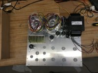
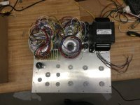
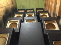
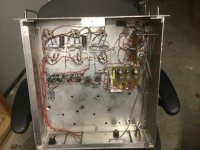
Trafos are all here, the prep is all finished on my speaker project (shooting Duartex on 20 PA cabs now), so fixing to ramp this thing back up again. Here’s what I’m proposing for the new layout. 19” form factor, with a 3U height because I have 4 nice front panels. Trafos, tubes, heatsink and caps stick out the top. The idea was to keep the signal routing for the amplifier section pretty much identical to the original prototype, and compact the power supply. Probably do the voltage regulators on a little perf board (like the bias pot board) because it will be easy to handle strings of zeners that way instead of point to point. All 3 hexfets on the common heat sink. First pic shows where everything on top side will go. 2nd shows what’re the other 2 transformers go, but mounted from underneath. 3rd is the original reference design. Anyone see anything that just isn’t a good idea? Drilling soon.....
Attachments
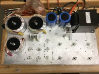
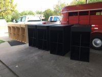
Finally finished the time consuming part of this..... I now have two complete chassis ready and now I get to resume actual electronics! So what was taking so long? Painting all these speaker cabs before winter makes it impossible. Now I’ve also got a shop floor covered in aluminum shards.
Attachments
Finally progress - real progress
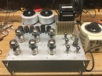
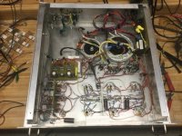
The first one of the final monoblock pair is almost done. It was working properly with the front end section plugged in directly and the power stage running thru a 300 watt bulb limiter this afternoon. Full power music test some time tomorrow. The second unit is to the point where I need to scavenge transformers off the prototype to finish it.
A couple minor updates. An extra RC in the feedback path for low frequency compensation (suppresses the volt or so of sub-1-Hz ringing when recovering from full power) and added transformer input coupling. I was using an LTP tube stage to add balanced XLR in, and but there was an incredible amount of HISS that I couldn’t figure out where it was coming from. Just did the balanced input the easy way after battling it for a week.
Attachments
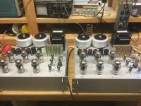
Well here they are!
Both amps completed, except for installing the bottoms on the cases. That will happen when they get racked.
Final schematics to be posted when I get to my other machine later. There were a couple minor mods. I did try the 475 volt power trafos in one of them, but ultimately just used the original 430 volt. Power only increased from 210 to 248 watts, despite going to a full 700 volts. 200 watts per channel into a pair of 2x15’s was playing as loud as I’d ever want anything to.
Attachments
Both amps completed, except for installing the bottoms on the cases. That will happen when they get racked.
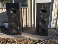
Congratulations! That's one hefty project by all measures. What kind of speakers will they be used with?
Right now I was using a pair of 2x15 + 2x8 +1” PA speakers. Custom build for small parties, just the best speakers I have for testing - fairly bulletproof. I have 12 Audax HM130Z0’s and a pair of AC G1 ribbons, to make a more “hi-fi” oriented version of them. The only thing to be decided is whether to use the Kappa15LFs or hold out for something “better” on the bottom.
Attachments
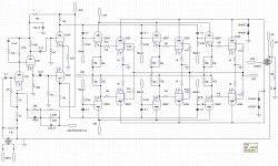
Final schematic set
A few updates from the original design:
Screen supply now taken from the 300V transformer. This experiment succeeded, unlike the 475V mian HT trafo experiment.
Main HT filter caps now 4x 470 uF, because I had a bunch of these.
One 68V zener in each stack dropped to 56. The latest batch of 68's were measuring 70, so it was needed to trim the voltages,
Added 1.33 meg resistor from bias pot wipers to -68V bias supply In case the pots get intermittent.
Increased coupling caps on concertina to 0.33 uF
Added additional low frequency feedback pole to reduce amount of feedback below band. Completely kills the ~2V p-p oscillation that still occurred with no load.
Used a 10k:10k transformer to couple the input and break any potential ground loops. Tried a 12AX7 differential input LTP, highly degenerated to a gain of 2, but it still had too much noise. Decided enough was enough and did it the easy way.
Attachments
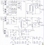
For no-load protection. Saves the output transformer from dangerous flyback voltages. If the voltage at a plate tries to go above 2X B+, the other side of the transformer goes below ground and the diodes clamp it. Without them the plates can reach for the sky when a tube cuts off with no load except the primary inductance. And I have already tested it - the other day I accidentally ran one of them without the dummy load for about 20 minutes, with music and visible clipping on the scope. The music still sounded clean - I was monitoring through a speaker and 1k ohm series resistor to keep the volume reasonable in the shop during extended testing.
- Status
- This old topic is closed. If you want to reopen this topic, contact a moderator using the "Report Post" button.
- Home
- Amplifiers
- Tubes / Valves
- We've got a heartbeat - 6x 6550 is alive