I am wondering what makes a MOSFET a good MOSFET as a buffer to drive the grid of a power tube (aka "PowerDrive")?
The older Tubelab docs show the 2SK2700, which is obsolete. The newer Baby Huey uses the STU9HN65M2 or FQFP2N60C parts. I am not surprised that these are N-channel high-voltage parts.
What other specs are important when choosing a MOSFET for the driver stage?
The older Tubelab docs show the 2SK2700, which is obsolete. The newer Baby Huey uses the STU9HN65M2 or FQFP2N60C parts. I am not surprised that these are N-channel high-voltage parts.
What other specs are important when choosing a MOSFET for the driver stage?
Last edited:
Select Vdrain so that at peak +Ve signal on the Source there is at least 25V across the mosfet. This will reduce input capacitance, that is another aspect to keep under control.
So it's only a question of voltage rating (enough to not blow up with the voltages in a given design) and the parasitic capacitance(s) (as low as possible)? Anything else that should be considered? Is linearity an issue, or are the typical switching-type MOSFETs fine?
A 600V FET is a good choice. The data-sheet capacitance of importance is Crss, and to a degree Coss.
When looking through the data sheets, look for the curves of capacitance versus Vds. The best FETs for source follower duty have low Crss/Coss, and do not change in a menacing way as Vds gets below 50V.
The FQFP2N60C is a Fairchild 'QFET', and you when comparing FETs, you will see that these behave relatively well for capacitance vs Vds. But do compare any others with 600V or 800V ratings, and 2-3A max. current (the low current ones have lower Crss/Coss)
As mentioned, design the circuit so that you have some headroom for Vds, when the driver's voltage swing is at maximum. Then, you can take less account of FET capacitance when Vds is below that value.
One thing to watch out for is that some manufacturers use log scales for capacitance vs Vds which initially might "look" worse than those that use a linear scale. Just take care when comparing different parts.
Hi
It's a follower stage, so to make sure it is really, really linear, use a constant current sink. You can go crazy and do something like Allen Wright's "super reg" circuit for inspiration perhaps. I found a big enough difference by just using a simple constant current sink on the follower.
If you are worried that transients will get "lost" etc. then I would not worry. Once the device is "On" it is ON. All those switching characteristics listed in specs sheets are for applications where the device is actually required to switch on and off. For a simple follower circuit, it is simply ON all the time.
The output impedance of your valve/tube differential amplifier needs to work with the reverse transfer capacitance value (Crss) to not get any audible HF roll-off. For most valves/tubes this is not a problem, except for ecc83. Too high Crss is a deal breaker for ecc83 in Baby Huey (for example). However, for driving a 300b (for example) you need to consider Coss too. Driving pentodes is usually pretty easy in comparison.
Then I start to look at the capacitance vs. Vds to give me an idea of what Vds we need to run the device at, taking into consideration all the headroom needed, as Yntolo and Rod already kindly noted.
Depending on the device and your circuit requirements, 25V across the device (at peak +Ve) might not be quite enough. You might find you need higher rail volts than what you happen to have in your power supply. Then you might decide that ecc83 is maybe not the best choice, as you go on an endless, foolish search for a device that might just not exist... 😱
Also, Some older mosfet specs sheets don't have any charts for capacitance vs. Vds, but they can still work well.
I've been using ZVN0545A with a DN2540 constant current "sink" for ecc83, but you must respect that 700mW limit. I ruined a few running them at 1W.... they actually sounded very nice at 1W (for few days) but they just got too hot and would eventually fail. Yes, there are ways to heatsink T0-92 devices, but I figured it is probably wiser to respect the specs sheet values...
You will naturally find differential stages with lower output impedance easier to work with. For example, you can go cheap and use IFRBC20 with ecc88 and 6SN7, etc. Again, I use dn2540 constant current sinks on them. In the right circuit, they do not sound like a device at all (which is what you want).
You can also spend more than 50 cents on the device though. Newer devices often have option for TO-220F with the heat sink tab insulated. I would consider that a definite bonus worth paying a bit extra for.
Ian
Last edited:
The 2SK2700 is obsolete, killed off a long time ago by ROHS. I don't believe that a lead free part was ever made. It was a good mosfet for PowerDrive in it's day, but there are far better parts available today.
It is unfortunate in todays fast changing electronics world that new parts are introduced, and if they don't find their way into a million unit a year market, they are killed off. I have been constantly chasing the "mosfet of the day" rabbit for years.
Today's current part is the STF3LN80K5. It is the recommended part for the new TSE-II board. It can eat 800 volts, has a rated Crss of 0.1 pF (more on that later) and a Coss of 11 pF. It is a TO-220 part with an insulated case.
Obviously the mosfet needs to handle the highest possible voltage seen in the amp. It can see full B+ on its drain at startup, and may see the full negative supply on its source, depending on the actual circuit application. The mosfet should incorporate internal Zener gate protection, or an external diode should be added. The startup transients in a tube amp can easily zap the gate in a mosfet.
Most mosfets made today are intended for switching use. They are often not even specified for continuous operation in the linear region. Safe Operating Area curves are not given for continuous DC, or may be WRONG (NXP parts)! This is usually not an issue for "normal" tube circuits, but should be considered for big tubes like the 833A or 845 where the signal swing can be a few hundred volts, or the idle current is high to drive a big grid positive.
Crss is the big one. This is the capacitance from the gate to the drain of the fet. The drain is usually bypassed such that it is an AC ground in a follower. The driver tube must drive directly into this capacitance.
ALL semiconductor devices exhibit Voltage Varying Capacitance effects. This means that there is a capacitor from the plate to (AC) ground on your driver tube that CHANGES dynamically with the signal voltage. Vacuum tubes exhibit this effect too! Yes, the space charge cloud is constantly changing size with applied signal voltage, but it is a lossy medium and its conductivity decreases as the distance from the cathode increases, so it is a far smaller factor that can usually be ignored. Either way we want to minimize these effects, or reduce them to a point where they don't matter.
Looking at the capacitance variations curves on the STF3LN80K5 reveals that the quoted 0.1pF only applies at exactly one point, 100 Volts Drain to Source. It is however under 1 pF from 45 to 600 volts. 1 pF is less than the capacitance of an average tube socket, so operating this part such that it stays in this range over all signal conditions is a good idea.
Some tubes work well in A2 or AB2, meaning that there are advantages to driving the control grid positive. The drain voltage on the mosfet should be high enough that you still have 45 volts across it when the grid is driven to its maximum positive voltage. The TSE-II puts +150 volts on the drain of the fet.
Ciss is the "input" capacitance of the fet measured from gate to source. The source stays at (nearly) the same voltage potential in a follower, so that the charge on this capacitance is not changing (much), so the driver tube doesn't see it. In practice there are slight changes since the Gm is not infinite, but they can be ignored. This is why a mosfet makes a better follower than a vacuum tube. Tubes have much lower Gm than mosfets, so that the "following" action is measurably imperfect, and changes with the tube current.
Coss has been mentioned a few times. This is the capacitance from source to drain. It is directly across the output of the fet, and in parallel with the grid (Miller) capacitance of the tube at AC. This capacitance is CHARGED by the mosfet on a positive going signal swing. The mosfet is essentially a voltage variable resistor that can go as low as RDSon (2.75 ohms in this case) when called upon. The Coss is not that important here as long as it is not ridiculously high.
This capacitance is DISCHARGED by the resistor (or CCS) from the source to the negative supply. So like any follower circuit, the drive currents, and time constants are NOT symmetrical.
A positive going transient is fed by RDSon from the drain supply, as the Coss of the mosfet is steadily increasing. 2.75 ohms can charge this pretty quickly. Assume a sharp negative going transient follows immediately. The mosfet is driven towards (or into) cutoff as the resistor or CCS from source to the negative supply attempts to discharge the combined capacitance of the fet and the Miller effects in the tube. A CCS will pull a constant current out of this capacitance, but a resistor to a high negative supply will be pulling a higher current than it does at an idle, partially offsetting the increased capacitance of the mosfet.
If you have plenty of voltage to play with I prefer a resistor on the source. The TSE-II runs 200 to 300 volts of negative supply and a 20K resistor to the source. It also has 150 volts on the drain so that the Coss stays in the under 10 pF range, less than Miller on most tubes.
It is unfortunate in todays fast changing electronics world that new parts are introduced, and if they don't find their way into a million unit a year market, they are killed off. I have been constantly chasing the "mosfet of the day" rabbit for years.
Today's current part is the STF3LN80K5. It is the recommended part for the new TSE-II board. It can eat 800 volts, has a rated Crss of 0.1 pF (more on that later) and a Coss of 11 pF. It is a TO-220 part with an insulated case.
What other specs are important when choosing a MOSFET for the driver stage?
Obviously the mosfet needs to handle the highest possible voltage seen in the amp. It can see full B+ on its drain at startup, and may see the full negative supply on its source, depending on the actual circuit application. The mosfet should incorporate internal Zener gate protection, or an external diode should be added. The startup transients in a tube amp can easily zap the gate in a mosfet.
Most mosfets made today are intended for switching use. They are often not even specified for continuous operation in the linear region. Safe Operating Area curves are not given for continuous DC, or may be WRONG (NXP parts)! This is usually not an issue for "normal" tube circuits, but should be considered for big tubes like the 833A or 845 where the signal swing can be a few hundred volts, or the idle current is high to drive a big grid positive.
Crss is the big one. This is the capacitance from the gate to the drain of the fet. The drain is usually bypassed such that it is an AC ground in a follower. The driver tube must drive directly into this capacitance.
ALL semiconductor devices exhibit Voltage Varying Capacitance effects. This means that there is a capacitor from the plate to (AC) ground on your driver tube that CHANGES dynamically with the signal voltage. Vacuum tubes exhibit this effect too! Yes, the space charge cloud is constantly changing size with applied signal voltage, but it is a lossy medium and its conductivity decreases as the distance from the cathode increases, so it is a far smaller factor that can usually be ignored. Either way we want to minimize these effects, or reduce them to a point where they don't matter.
Select Vdrain so that at peak +Ve signal on the Source there is at least 25V across the mosfet…… 25V across the device (at peak +Ve) might not be quite enough.
Looking at the capacitance variations curves on the STF3LN80K5 reveals that the quoted 0.1pF only applies at exactly one point, 100 Volts Drain to Source. It is however under 1 pF from 45 to 600 volts. 1 pF is less than the capacitance of an average tube socket, so operating this part such that it stays in this range over all signal conditions is a good idea.
Some tubes work well in A2 or AB2, meaning that there are advantages to driving the control grid positive. The drain voltage on the mosfet should be high enough that you still have 45 volts across it when the grid is driven to its maximum positive voltage. The TSE-II puts +150 volts on the drain of the fet.
Ciss is the "input" capacitance of the fet measured from gate to source. The source stays at (nearly) the same voltage potential in a follower, so that the charge on this capacitance is not changing (much), so the driver tube doesn't see it. In practice there are slight changes since the Gm is not infinite, but they can be ignored. This is why a mosfet makes a better follower than a vacuum tube. Tubes have much lower Gm than mosfets, so that the "following" action is measurably imperfect, and changes with the tube current.
Coss has been mentioned a few times. This is the capacitance from source to drain. It is directly across the output of the fet, and in parallel with the grid (Miller) capacitance of the tube at AC. This capacitance is CHARGED by the mosfet on a positive going signal swing. The mosfet is essentially a voltage variable resistor that can go as low as RDSon (2.75 ohms in this case) when called upon. The Coss is not that important here as long as it is not ridiculously high.
This capacitance is DISCHARGED by the resistor (or CCS) from the source to the negative supply. So like any follower circuit, the drive currents, and time constants are NOT symmetrical.
A positive going transient is fed by RDSon from the drain supply, as the Coss of the mosfet is steadily increasing. 2.75 ohms can charge this pretty quickly. Assume a sharp negative going transient follows immediately. The mosfet is driven towards (or into) cutoff as the resistor or CCS from source to the negative supply attempts to discharge the combined capacitance of the fet and the Miller effects in the tube. A CCS will pull a constant current out of this capacitance, but a resistor to a high negative supply will be pulling a higher current than it does at an idle, partially offsetting the increased capacitance of the mosfet.
If you have plenty of voltage to play with I prefer a resistor on the source. The TSE-II runs 200 to 300 volts of negative supply and a 20K resistor to the source. It also has 150 volts on the drain so that the Coss stays in the under 10 pF range, less than Miller on most tubes.
A CCS will pull a constant current out of this capacitance, but a resistor to a high negative supply will be pulling a higher current than it does at an idle, partially offsetting the increased capacitance of the mosfet.
If you have plenty of voltage to play with I prefer a resistor on the source. The TSE-II runs 200 to 300 volts of negative supply and a 20K resistor to the source. It also has 150 volts on the drain so that the Coss stays in the under 10 pF range, less than Miller on most tubes.
Good point George. I guess I could use a negative rail more often too. Some of my mains transformers have a winding I could rig up for that.
Many thanks
Ian
And what about SiC FETs?
I personally have not tried them
Another point I forgot to make.....
If the mosfet fails, it usually fails to a short. This will put the drain voltage directly on the grid of your (possibly expensive) output tube. Put a low valued (100 ohm or so) 1/8 or 1/4 watt resistor in series with the grid to act as a fuse.
Excellent easy to understand explanation thank you Tubelab.
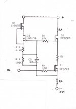
To get low FET follower capacitance I have adapted Gary Pimms cascode CCS to a cascode FET follower (see attached).
The bottom FET (I used IRF820) is working a near constant voltage.
Seemed to work ok.
To get low FET follower capacitance I have adapted Gary Pimms cascode CCS to a cascode FET follower (see attached).
The bottom FET (I used IRF820) is working a near constant voltage.
Seemed to work ok.
Attachments
Thanks, do you have an LTspice model for it?Today's current part is the STF3LN80K5. It is the recommended part for the new TSE-II board. It can eat 800 volts, has a rated Crss of 0.1 pF (more on that later) and a Coss of 11 pF. It is a TO-220 part with an insulated case.
Tubelab,
The STF3LN80K5 has impressively low capacitances but is rated only for 20 watts dissipation so I'm not sure it would be suitable to drive an 833 in A2 with the required 150--200mA max grid current.
Any suggestions for a FET that has (similarly) low capacitances but has the dissipation sufficient for an 833?
stay safe
tim
Hi V4lve lover, according to Mouser this MOSFET is obsolete. Perhaps Tim could find some “old” stock somewhere?
I run the STF3LN80K5’s in a test with 400 VDC as a source follower driving KT150 tubes (conventional G1 drive). They draw 10 mA each, with a 33 Kohm resistor from source to ground. These resistors become quite hot (3.3 Watt continuous dissipation).
Regards, Gerrit
I run the STF3LN80K5’s in a test with 400 VDC as a source follower driving KT150 tubes (conventional G1 drive). They draw 10 mA each, with a 33 Kohm resistor from source to ground. These resistors become quite hot (3.3 Watt continuous dissipation).
Regards, Gerrit
I checked and TME still has stock.
You may want to substitute a CCS IC for that resistor, those can handle the dissipation. 10M45S is a good one there
You may want to substitute a CCS IC for that resistor, those can handle the dissipation. 10M45S is a good one there
Hi, I do have 10M45S devices around, so I could give this a try. Do you think this will make any difference (besides dissipation)? How about RMS voltage swing and distortion?
Regards, Gerrit
Regards, Gerrit
- Home
- Amplifiers
- Tubes / Valves
- "PowerDrive": how to choose the right MOSFET part?