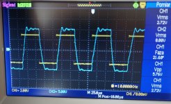
1. I was looking for the reason why the signal was asymetrical. I found out that to square signal a small amount of DC voltage was added. And this was probably the reason.Well done for working through that.
I think one reason the X-Y plot is not shaped more like a circle/ellipse is related to why your squarewave response was not symmetric. You seem to have a gain or non-linear difference between each side of the balanced circuit paths. Perhaps best to probe through your circuit stages (with no feedback). The signal waveforms at the PI stage (eg. at V4/1 input grid and V4/2 input grid) should be the same magnitude but opposite phase, and with no distortion for a sinewave input.
I also found out that driving two channels with the same magnitude of the sinus signal (1kHz) I have at the output of OTP signals of 6,8V(R) and 7,2(L). So I measures the value of sinus signal at both grids of V4/1 and V4/2 - they were 12,2VRMS(R) and 13,20VRMS(L) respectively. At the first stage output was 1,60VRSM at both channels. Measured DC voltages at push -pull tubes cathodes were 32,1VDC-31,9VDC(R) and 30,0DC-30,7VDC(L). Quiescence currents according to mA are 65mA-64mA.
Is it because the pairs of power tubes EL34 TungSol are not properly matched?
2. Using the LF the generator I found that there are still resonances at low frequencies i the amplifier. When going from 1Hz up you can notice them up to about 15Hz - but when going down with frequecy the signal is OK from 20Hz to lets say 7-8Hz. Something like 'hysteresis'. Does the situation need further treatment or I can take the thing easy?
3. I studied the artical 'The care and Treatment of Feedback...' which is also about HF ringing but I think first I must straighten the 'motor boating' problem.
Jarek
V4/1 and V4/2 have similar cathode voltages in each amp (L & R), and I assume screens are all going to their respective UL taps, and I think you are saying that the input grid signal levels to V4/1 and V4/2 are the same within each amp (just at a different level to the other amp), so it may well be the EL34 gain balance.
If you set up the scope and signal generator for a square wave test and look at the output waveform and see some ringing on top section but not on bottom section of squarewave, then swap V4/1 and V4/2 around and see if the output waveform asymmetry follows the tube swap.
Do you get the same output squarewave asymmetry on the other amp ?
If you connect two 100k resistors in series and connect the ends to V4/1 and V4/2 input grids, and probe the centre point of the two 100k resistors then the scope should show zero signal if the input stage and PI stage have zero distortion and perfect symmetry (as long as the two 100k resistors are closely matched in value). That is another test for symmetry within the amp.
Yes they are without distortion.Well done for working through that.
I think one reason the X-Y plot is not shaped more like a circle/ellipse is related to why your squarewave response was not symmetric. You seem to have a gain or non-linear difference between each side of the balanced circuit paths. Perhaps best to probe through your circuit stages (with no feedback). The signal waveforms at the PI stage (eg. at V4/1 input grid and V4/2 input grid) should be the same magnitude but opposite phase, and with no distortion for a sinewave input.
Next activities:
- I was trying to equel the plate voltages of V1 tubes (see updated schematic #151 - from 18th April 2022) . I checked the values of all elements in the stages and they were equel in both channels. So there must be something wrong with the JJ tube maching – I ordered the new pair from China with lettering Full Music!?).
- I did a lot of experiments with introduced step filter in the channels of the amplifier before the power stage ( Rsn+Csn). I played with different values of the elements Rsn=15k, 5k Csn= 10nf-1nf-470pF, 68pF-34pF but without any serious improvements.
- In the cathode circuit of power stage I did tests with pure resistor 460R vs “220R + Zener diode resistor”. Seems to me the resistance is better as the values of cathode voltages were more closer when they were used (about 0.5V difference max).
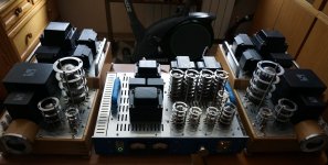
- Because of coming Easter holidays I decided to move the P-P EL34 amplifier to my small audio room and do some sonic tests there. See of the P-P amp photo with its older brothers at the sides. Then I‘m planning to do some tests with tube swap. Have the nice time during the holidays.
Attachments
<trobbins>
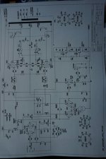
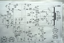
Some observation done during last tests. See actual schematic #153 enclosed.
I did some sonic tests and I found that middle tones and treble are OK but the low bass is missing so I took the amp to the bench and did some measurements according to enclosed schematic.
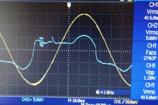
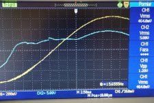
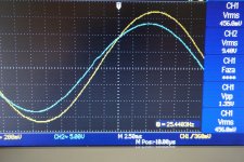
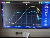
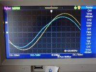
See scope plots done with the constant voltage at the input sinus signal about 490mVRMS and voltage output Rload=4Ohm of both channels. They show decreasing of the magnitude of signal when going down with frequency to 25Hz-10Hz. I also detected the changing of the shape of output plot because of LF ringing. But generally some progress has been done because the needle resonance is not present at the Ampermeters.
There is big difference of DC V1 quiescence plate voltage L=73V vs R=68,2V in the channels. Is it possible for matched pair of 12AX7 tubes? I checked all the resistors in the stage in both channels and they are equal.
I used shelf filters with R=22nF and R=1M at both channels. Are the used values correct?
I also tested the amplifier behaviour taking into consideration the resonances when using simple voltage regulator for 140VDC (R+Zener diode) and more complicated circuit with MOSFET transistor. No differences were detected.
Test with two 100kOhm resistors at the grids of EL34 has been done. You can see results at the schematic.
I am awaiting for your remarks how to solve the issues that are still present in the amplifier mainly in the low frequency region. Jarek
Some observation done during last tests. See actual schematic #153 enclosed.
I did some sonic tests and I found that middle tones and treble are OK but the low bass is missing so I took the amp to the bench and did some measurements according to enclosed schematic.
See scope plots done with the constant voltage at the input sinus signal about 490mVRMS and voltage output Rload=4Ohm of both channels. They show decreasing of the magnitude of signal when going down with frequency to 25Hz-10Hz. I also detected the changing of the shape of output plot because of LF ringing. But generally some progress has been done because the needle resonance is not present at the Ampermeters.
There is big difference of DC V1 quiescence plate voltage L=73V vs R=68,2V in the channels. Is it possible for matched pair of 12AX7 tubes? I checked all the resistors in the stage in both channels and they are equal.
I used shelf filters with R=22nF and R=1M at both channels. Are the used values correct?
I also tested the amplifier behaviour taking into consideration the resonances when using simple voltage regulator for 140VDC (R+Zener diode) and more complicated circuit with MOSFET transistor. No differences were detected.
Test with two 100kOhm resistors at the grids of EL34 has been done. You can see results at the schematic.
I am awaiting for your remarks how to solve the issues that are still present in the amplifier mainly in the low frequency region. Jarek
Attachments
-
 10Hz_sinus_L_comp.jpg1.1 MB · Views: 73
 -
 15Hz_sinus_L_comp.jpg343.4 KB · Views: 47
 -
 25Hz_sinus_L_comp.jpg309.2 KB · Views: 36
 -
 10Hz_sinus_R_comp.jpg279.2 KB · Views: 46
 -
 15Hz_sinus_R_comp.jpg317.6 KB · Views: 49
 -
 23Hz_sinus_R_comp.jpg278.3 KB · Views: 65
 -
 P-P_schematic 153_26.04.22_comp.jpg297 KB · Views: 62
Jarek, if you swap 12AX7 between channels then does the 73V and 68.2V idle anode levels move with the tube? Your schematic shows that each channel uses one 12AX7 tube with both triodes wired in parallel - so your 73V and 68.2V discrepancy isn't related to triode matching within a 12AX7 but rather is related to the matching of the four triodes within the two 12AX7 tubes. A five volt idle anode voltage difference is not really going to make any difference in performance except towards the full-swing limits.
You will need to assess the design theory of step networks and relate that to your particular circuit values to clarify whether the step network values are appropriate - that is one of the design efforts you take on when making up your own design modifications.
I am unsure if you have interpreted the intended use of the two 100k resistors. One end of each 100k connects to each EL34 grid, and the other two ends of the 100k resistors are connected together as a floating mid-point node which you then probe with your scope - any non-zero voltage at that mid-point indicates unbalance between the drive voltages being presented to the EL34 inputs.
<Jarek, if you swap 12AX7 between channels then does the 73V and 68.2V idle anode levels move with the tube? Your schematic shows that each channel uses one 12AX7 tube with both triodes wired in parallel - so your 73V and 68.2V discrepancy isn't related to triode matching within a 12AX7 but rather is related to the matching of the four triodes within the two 12AX7 tubes. A five volt idle anode voltage difference is not really going to make any difference in performance except towards the full-swing limits.>
I will do father test with swapping the tube of Full Music pair. I will also play with another pair of 12AX7 manufactured by JJ company from Czech’s Republic.
<You will need to assess the design theory of step networks and relate that to your particular circuit values to clarify whether the step network values are appropriate - that is one of the design efforts you take on when making up your own design modifications.>
You are right.
<I am unsure if you have interpreted the intended use of the two 100k resistors. One end of each 100k connects to each EL34 grid, and the other two ends of the 100k resistors are connected together as a floating mid-point node which you then probe with your scope - any non-zero voltage at that mid-point indicates unbalance between the drive voltages being presented to the EL34 inputs.>
See the schematic enclosed to #524. I think the resistor are properly located - see dot lines. Listed values are measured by voltmeter at DC volt range. The values are for L channel and ( ) R channel in brackets. If the measurements with sinus /square signals by the scope are necessary let me know.
Yesterday I sent the noisy mains 250VA transformer for the vacuum reimpregnation to the manufacturer. I will continue the tests after I install it again in my P-P amplifier. Thanks for your attention.
We already have more than three 3 millions of refugees from Ukraine in Poland. Voluntarists have a lot of work with them. Jarek