Hi All,
I've been off for a while : no time, not much money to devote to...
My last Audio Hi-Fi build I posted was The ULTIMATE 300B :
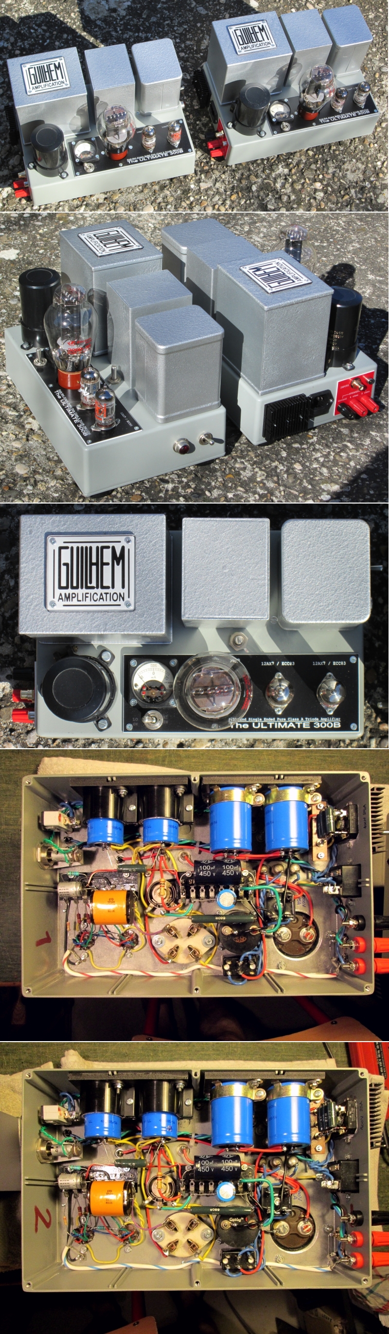
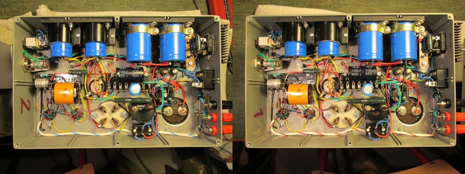
In the same vein (same format, same chassis) I am building the prototype of what should be (one day) The ULTIMATE OTL6080 :
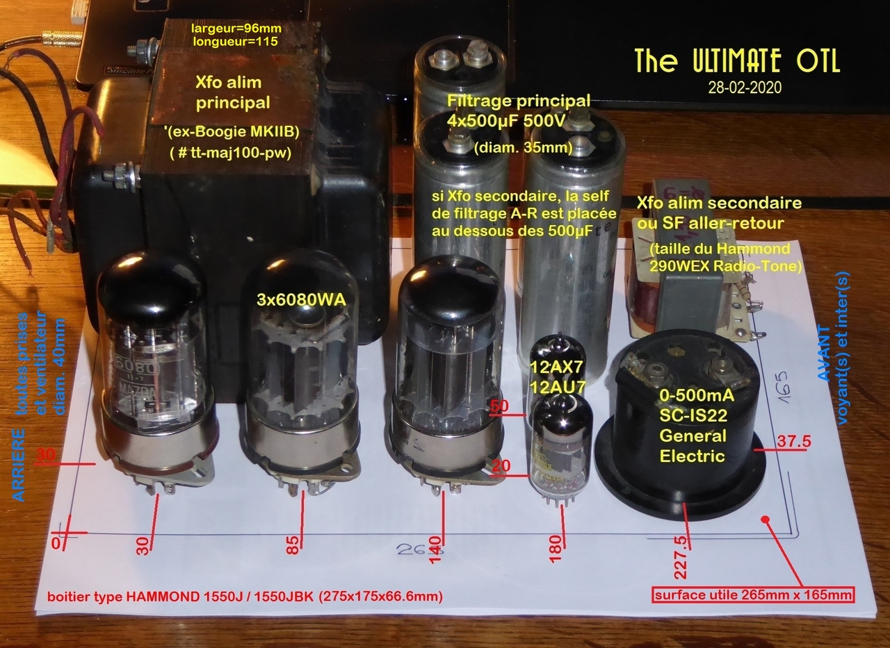
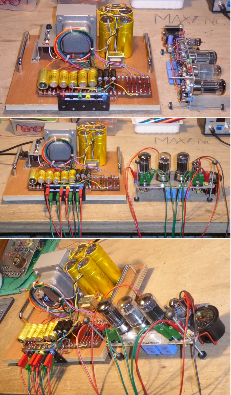
General layout of what should be a mono block :
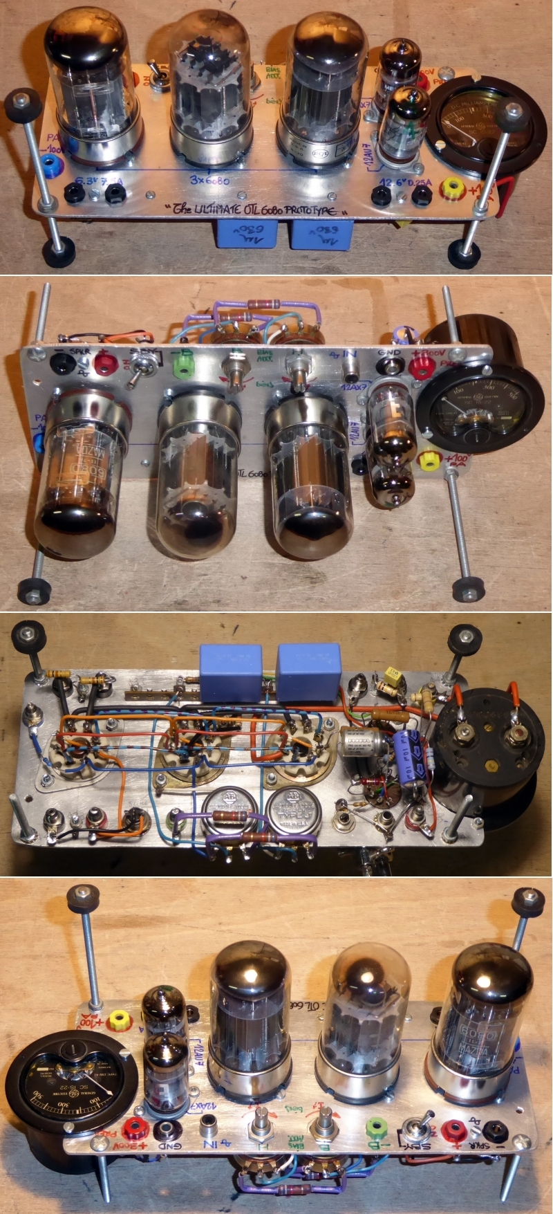
Amp section prototype only, for tests and qualification purposes, same disposition as layout :
I have to build the PSU prototype now, in the days to come.
Wait and See !
A+!
I've been off for a while : no time, not much money to devote to...
My last Audio Hi-Fi build I posted was The ULTIMATE 300B :
In the same vein (same format, same chassis) I am building the prototype of what should be (one day) The ULTIMATE OTL6080 :
General layout of what should be a mono block :
Amp section prototype only, for tests and qualification purposes, same disposition as layout :
I have to build the PSU prototype now, in the days to come.
Wait and See !
A+!
Sweet.
Looks like the 6080s are in parallel, from the photographs. OTL,huh? 100 V anode? Hard to tell in your photos, or maybe easy… I'm just to tired to trace the wires.
100 V, 375 mA … inside the triple envelope limit of power dissipation.
I wonder … looks like plate resistance is about 280 Ω a unit or 90 Ω total in parallel at 125 mA per bulb. That in turn is computationally in series with the OTL load. Hmmm… it still sounds OK, just not a lot of watts to the load, compared to internal dissipation.
37 W, times 8 Ω ÷ 100 Ω = 3 or so watts output power.
Was this your calculation?
It'd be better to wire up your speakers' cones in some sort of series additive configuration, AND have 16 Ω cones, if you can find them.
⋅-⋅-⋅ Just saying, ⋅-⋅-⋅
⋅-=≡ GoatGuy ✓ ≡=-⋅
Hi @GoatGuy and thanks !
Looks like the 6080s are in parallel, from the photographs.
Yes.
OTL,huh? 100 V anode?
Yes.
100 V, 375 mA
I think that I will choose a 100mA idle current per triode, since it is intended to operate in class AB.
I wonder … looks like plate resistance is about 280 Ω a unit or 90 Ω total in parallel at 125 mA per bulb. That in turn is computationally in series with the OTL load. Hmmm… it still sounds OK, just not a lot of watts to the load, compared to internal dissipation.
37 W, times 8 Ω ÷ 100 Ω = 3 or so watts output power.
Was this your calculation?
I did not made calculations, I start from my previous experiences about OTL amplifiers.
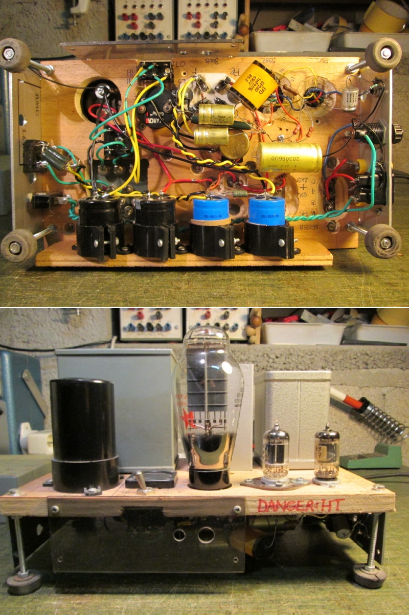
These ones below - that I made in mid-90s - were giving 20W RMS output on 8R load at onset of clipping. The output impedance was 20R. They were monsters of 25kg each :
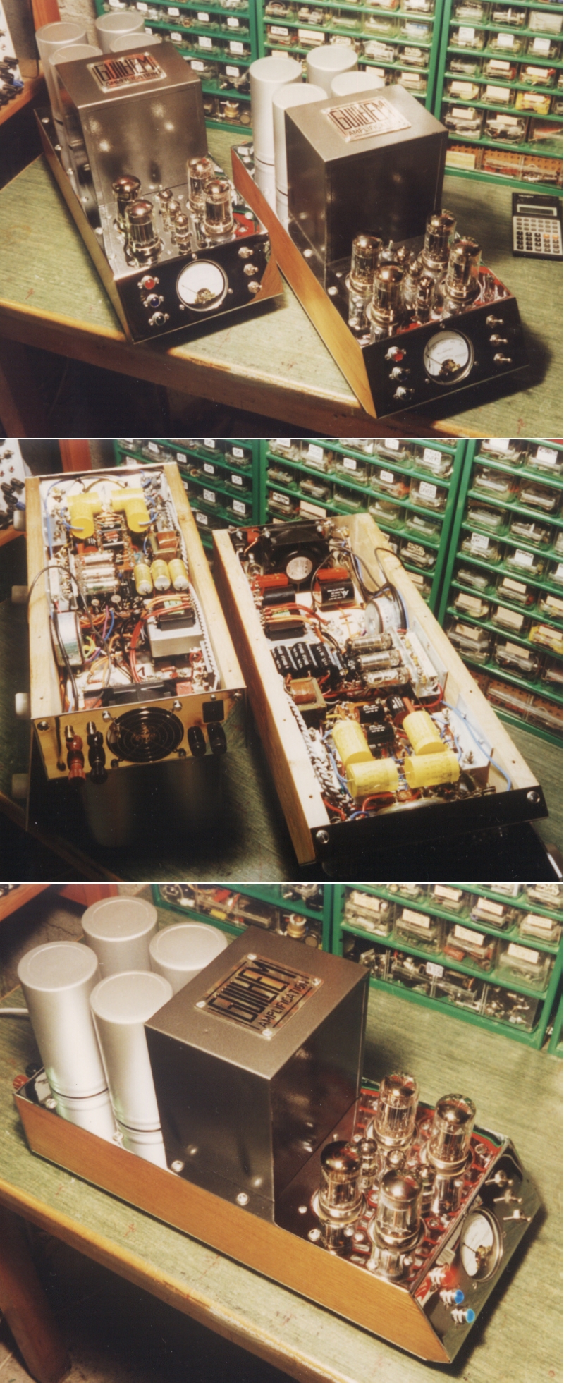
They used 4x6080 for 20W, so for 3x6080, I think I can expect circa 6-8W on 8R for my way much compact ULTIMATE OTL6080...
Wait and See !
A+!
Looks like the 6080s are in parallel, from the photographs.
Yes.
OTL,huh? 100 V anode?
Yes.
100 V, 375 mA
I think that I will choose a 100mA idle current per triode, since it is intended to operate in class AB.
I wonder … looks like plate resistance is about 280 Ω a unit or 90 Ω total in parallel at 125 mA per bulb. That in turn is computationally in series with the OTL load. Hmmm… it still sounds OK, just not a lot of watts to the load, compared to internal dissipation.
37 W, times 8 Ω ÷ 100 Ω = 3 or so watts output power.
Was this your calculation?
I did not made calculations, I start from my previous experiences about OTL amplifiers.
These ones below - that I made in mid-90s - were giving 20W RMS output on 8R load at onset of clipping. The output impedance was 20R. They were monsters of 25kg each :
They used 4x6080 for 20W, so for 3x6080, I think I can expect circa 6-8W on 8R for my way much compact ULTIMATE OTL6080...
Wait and See !
A+!
Last edited:
Superbe.
In your first pics, I assume from left to right you have the PT, a big choke then the additional PT ?
Schematic?
Merci.
Brice.
Thanks @Brice !
Yes, you guessed it right : PT / Ch / OT.

The prototype looked like that- it worked for years...
Well, the schematic is a personal development, not derived from the usual 300B Audio Note or the like you see usually...
A+!
Love the look of those amps, even the prototypes are super cool!
Thanks @gideon1990 !
A+!
Super cool.
Do you have safety in place in case a power tube goes banana ?
I have to admit, OTL amps scare me, well scare my speakers
Well, with my previous OTL project built in 1994 :
I experienced tube failures during my security tests (flashing, red plating) and never the speakers suffered. I even made tests with missing and defective power tubes : no way.
The key solution is to design a PSU which is not DC coupled with GND, just like Julius Futterman did. No DC can transit via the speakers, only via the power tubes, as they are connected in serie.
A+!
Great. Impressive build.
This is why I never venture in the OTL space.
I've read most of Julius work and wasn't convinced of the safety of these amps.
I know there are other designs in theory "safe" for the speakers, but wasn't brave enough to see my woofers melt.
I am now exploring full DC coupled PP design instead. All fun.
Thanks for sharing.
It is not difficult to include a safety circuit that switch off the amplifier output if there is exessive DC on the output. We use a window comparator that switch of anode voltage to the output tubes if DC is above ~0.5V, as an additional safety measure we also include fuses from the anode supply to each tube, this is more than enough to ensure safety.
BTW, our amplifiers are DC coupled on the output.
BTW, our amplifiers are DC coupled on the output.
Great. Impressive build.
This is why I never venture in the OTL space.
I've read most of Julius work and wasn't convinced of the safety of these amps.
I know there are other designs in theory "safe" for the speakers, but wasn't brave enough to see my woofers melt.
I am now exploring full DC coupled PP design instead. All fun.
Thanks for sharing.
Yes, it's the common belief about OTL amps to be suspicious about the DC offset risk in the speaker output inducing damage.
In fact, it mainly depend on the output stage and PSU configurations : some maybe dangerous - requiring a safety circuit - others not...
I'll post a schematic about that soon.
A+!
I could perform the first tests of my ULTIMATE OTL 6080 :

Here are the waveform for 8WRMS output / 8R :

Max continuous power output at onset of clipping, @440Hz sinus, resistive load :
@4R load = 4.5WRMS
@8R load = 8.0WRMS
@16R load = 12.5WRMS
Output resistance (load variation method) :
Rs = 17.5R
Input sensivity for 8WRMS 8R 440Hz sinus :
Vin = 0.63VRMS
No additional negative feedback loop.
The clipping waveform is symmetrical, and starts with a soft clipping at high loads (>8R) - sorry, I did not take pics, but I will...
I did not determined the bandwith yet.
Well, these results are promising and encouraging...
A+!
Here are the waveform for 8WRMS output / 8R :
Max continuous power output at onset of clipping, @440Hz sinus, resistive load :
@4R load = 4.5WRMS
@8R load = 8.0WRMS
@16R load = 12.5WRMS
Output resistance (load variation method) :
Rs = 17.5R
Input sensivity for 8WRMS 8R 440Hz sinus :
Vin = 0.63VRMS
No additional negative feedback loop.
The clipping waveform is symmetrical, and starts with a soft clipping at high loads (>8R) - sorry, I did not take pics, but I will...
I did not determined the bandwith yet.
Well, these results are promising and encouraging...
A+!
Last edited:
I could check the bandwith today : 5hz - 120KHz
@-3dB, sinus 440Hz reference, power output 8WRMS / 8R.
The best working condition is under 16R load though. It's not surprising since the Rs of the amp is 17.5R. I tested "random, untested, unmatched" 6080 tubes and can say that this amp is a "10WRMS / 16R continuous power guaranteed", no matter.
I will have to do dynamic tests to see the behavior of the output stage.
Wait and See...
A+!
Sounds good. I am waiting
By dynamic tests you mean response to square signal / frequency?
Or response to pings, capacitor loading to see stability, etc...
Do you plan to also measure the %THD too?
Boujou!
Thanks !
The square signal response doesn't show instabilities - it's quite normal, since the amp has no NFB and no output transformer :

This is a very simple, Futterman first circuit-based design (reputedly called H1 ? The circuit that Julius Futterman patented in the early 50s...)
The goal is to built 2 compact OTL monoblocks (chassis = 275x175x67mm) :
Nothing should occur with a capacitor at the output too - for the same reasons and by my previous experiences of OTL circuit - but it's worth to check to be affirmative : good reminder...
Yes right, it's rather response to high amplitude pings and tone bursts to see how reacts the PSU in terms or recovery. The quick tests I made seemed to be good, but more serious / severe ones have to be made to be conclusive.
I also imagined a Fixed / Cathode bias switching of the power stage : I'll have to experiment it...
About the THD - for the moment, I have no mean to measure it because the old software I used is on a dead WXP laptop... And is not compatible with W7 or over ! Too bad : it measured IMD, THD, harmonic spectrum...
So I'll have to search another software. I'm thinking about ARTA : do you practise it ? Or do you know something else in that field ?
Wait and See...
A+!
Yesterday, I made several tests and a rudimentary listening check...
I tested with 2 and 1 6080 instead of 3. Here are the results :
3x6080 :
power output = 12WRMS
output impedance = 19.8R
theoric calculation = 19.44R
2x6080 :
power output = 5.8WRMS
output impedance = 29.6R
theoric calculation = 29.16R
1x6080 :
power output = 2.3WRMS
output impedance = 56.5R
theoric calculation = 58.3R
- power output is measured @440Hz sinus, onset of clipping, 16R resistive load.
- output Z is measured by the classic "half output voltage" method.
- output Z theoric calculation is given by : Zout = Ri/2(1+µ) with RI determined at 350R for the plate voltage at 115VDC of my prototype.
The amp worked all the afternoon in the 3x6080 version, and no issue occured : instability, overheat, characteristics drift...
The test on a small 2-way, 8R low efficiency bass-reflex (88dB) JVC test enclosure showed way enough loudness, without any dynamic offset movement of the speaker cone (which was one of my main concern) at maximum power.
The loudspeaker (a 5" mid-bass) sure moves greatly on bass and percussions but is tight-handled by the amp, like a good OTL amp would do. No flabbiness or looseness in cone displacement.
Next steps :
- reduce the slope of the square wave tops at low frequencies.
- eradicate the little remaining 100Hz ripple heard in the speaker.
Tests are quite conclusive and promising for the moment. Julius Futterman's ideas were good...
Here's the link to Mr Futterman's patent, from which I derived my prototype circuit :
US2773136A - Amplifier
- Google Patents
Wait and See...
A+!
Last edited:
Update :
- I increased the coupling caps at the 6080 grids from 1µF/630V to 10µF/630V in order to flatten the tops of the square waves at low frequencies.
- I made a mistake in my bandwith checking - too hastily done ! - a new and more accurate check with these 10µ caps gives now 1.3Hz - 250KHz @-3dB, 440Hz sinus, 5.85V / 2.2W RMS output 16R.
Here are the pictures :
At the suggestion of member @Brice, I tested the stability to capacitive load at the input.
Well, I don't know if I used the good method, but I simply put a 27µF/630V capacitor across the 16R resistive load... Imagining that it would more or less simulate a low pass cap of a 12dB/Oct woofer filter !
Here are the pictures :
I notice a little instability at 4400Hz... I wonder if a normal amp (tube or transistor) would behave the same, though.
A+!
- I increased the coupling caps at the 6080 grids from 1µF/630V to 10µF/630V in order to flatten the tops of the square waves at low frequencies.
- I made a mistake in my bandwith checking - too hastily done
! - a new and more accurate check with these 10µ caps gives now 1.3Hz - 250KHz @-3dB, 440Hz sinus, 5.85V / 2.2W RMS output 16R. Here are the pictures :
An externally hosted image should be here but it was not working when we last tested it.
At the suggestion of member @Brice, I tested the stability to capacitive load at the input.
Well, I don't know if I used the good method, but I simply put a 27µF/630V capacitor across the 16R resistive load... Imagining that it would more or less simulate a low pass cap of a 12dB/Oct woofer filter !
Here are the pictures :
An externally hosted image should be here but it was not working when we last tested it.
I notice a little instability at 4400Hz... I wonder if a normal amp (tube or transistor) would behave the same, though.
A+!
Last edited:
On tube amps, here is what I do.
HF stability tests are performed using a 1 watt 10 kHz square wave (as measured when normally loaded) with scope hung on the output, and then the output shorted, opened, or operated in a capacitance only load ranging from .005uF to 1.0uF.
At some value, the cap only load will certainly produce a maximized ring on the tops and bottoms of the square waveform, but should never cause it to break into full blown oscillation.
- Home
- Amplifiers
- Tubes / Valves
- The ultimate OTL6080