I'm hoping some might be interested in evaluating this derivative design for a computer desk amp I drew up.
Asking for any input at all about this schematic I drew up for a computer desk amp, errors, improvements or if its all just junk! Firstly I have to say that the amplifier portion of this diagram is not my design, it was derived from two interesting schematics I found at the Electra-Print site. But all the switching, power supply, bells and whistles, case, etc. I am attempting to design myself.
Electra Print credits:
Input idea:
Electra-Print.com PVA Pre-Amplifier w/70 Hz Cut & Bass Volume Control
Amplifier:
https://www.electra-print.com/docs/6bx7se0001.pdf
The purpose of this project is a design that will be used to drive a set of 5 to 6 inch near-field speakers that typically roll off fast below 70Hz and a small powered sub-woofer under the desk. I spend a lot of time at my desk organizing my 300,000 track library of FLAC files, researching a lifetime jazz-history hobby, and doing DJ work for the local ballroom dance community here. So I thought what better project for me than a computer desk amp and the satisfaction of having done some of the design myself over a kit. My wife often wants to connect her phone, we have an Alexa and a Tidal account and occasionally a need to plug in a headphone out of something else portable. Also it has speaker and headphone listening modes. Currently I use a Teac class D amp at my desk with similar source input capabilities.
Some circuit explanations:
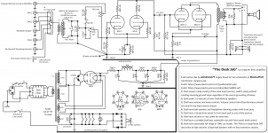
C1 and R3 form a 72Hz cutoff high-pass filter when engaged by S6, or the desktop speakers can be run full-range. The send to the sub-woofer is full range as that has its own low-pass filter. The voltage doubler in the 6.3 volt filament winding is for a 12V case boxer fan. The amp will be mounted in a "two story" case to reduce its horizontal footprint, a bottom chassis and a top chassis. The power supply chassis at the bottom floor meaning the rectifier tube is inside the wooden box so I want to cross ventilate the box with the fan and some perforated metal to still see the tube inside. All other tubes will be on the top floor chassis exposed. I indicated the ground bus for each "floor" of the case (see jumper). I dont know my voltages yet, but I have several Antek torroids to choose from in stash, I was going to parallel the HV windings to reduce the transformer impedance and not waste a winding. I used a hybrid bridge rectifier in the hopes of alleviating the turn on surge that way.
In addition to any criticism I have two main questions remaining if anyone can help...
1) What final voltage for B+ should I arrive at?
2) Would a 1.6K OPT work? Electra Print specifies a 2K OPT but I have in my stash a pair of OneElectron UBT1's just collecting dust waiting for a project. Those are rated 1.6K at 160ma. Do you think I can get away with using the 1.6K UBT1 transformer without any changes?
3) I dont know Spice yet, so I expect to be doing this by trial and error.
Asking for any input at all about this schematic I drew up for a computer desk amp, errors, improvements or if its all just junk! Firstly I have to say that the amplifier portion of this diagram is not my design, it was derived from two interesting schematics I found at the Electra-Print site. But all the switching, power supply, bells and whistles, case, etc. I am attempting to design myself.
Electra Print credits:
Input idea:
Electra-Print.com PVA Pre-Amplifier w/70 Hz Cut & Bass Volume Control
Amplifier:
https://www.electra-print.com/docs/6bx7se0001.pdf
The purpose of this project is a design that will be used to drive a set of 5 to 6 inch near-field speakers that typically roll off fast below 70Hz and a small powered sub-woofer under the desk. I spend a lot of time at my desk organizing my 300,000 track library of FLAC files, researching a lifetime jazz-history hobby, and doing DJ work for the local ballroom dance community here. So I thought what better project for me than a computer desk amp and the satisfaction of having done some of the design myself over a kit. My wife often wants to connect her phone, we have an Alexa and a Tidal account and occasionally a need to plug in a headphone out of something else portable. Also it has speaker and headphone listening modes. Currently I use a Teac class D amp at my desk with similar source input capabilities.
Some circuit explanations:
C1 and R3 form a 72Hz cutoff high-pass filter when engaged by S6, or the desktop speakers can be run full-range. The send to the sub-woofer is full range as that has its own low-pass filter. The voltage doubler in the 6.3 volt filament winding is for a 12V case boxer fan. The amp will be mounted in a "two story" case to reduce its horizontal footprint, a bottom chassis and a top chassis. The power supply chassis at the bottom floor meaning the rectifier tube is inside the wooden box so I want to cross ventilate the box with the fan and some perforated metal to still see the tube inside. All other tubes will be on the top floor chassis exposed. I indicated the ground bus for each "floor" of the case (see jumper). I dont know my voltages yet, but I have several Antek torroids to choose from in stash, I was going to parallel the HV windings to reduce the transformer impedance and not waste a winding. I used a hybrid bridge rectifier in the hopes of alleviating the turn on surge that way.
In addition to any criticism I have two main questions remaining if anyone can help...
1) What final voltage for B+ should I arrive at?
2) Would a 1.6K OPT work? Electra Print specifies a 2K OPT but I have in my stash a pair of OneElectron UBT1's just collecting dust waiting for a project. Those are rated 1.6K at 160ma. Do you think I can get away with using the 1.6K UBT1 transformer without any changes?
3) I dont know Spice yet, so I expect to be doing this by trial and error.
Attachments
Several observations…
There is no conceivable reason for 10,000 µF at C2; The LF roll-off corner is defined by
Lets look at the C1 value. You say '72 Hz', ok… plug in:
Having nominal current-balancing resistors for the slaved-in-parallel first stage triodes isn't a bad idea. 36 Ω is kind of weenie. Except for a little gain lost, 220 to 470 Ω resistors would better balance the current. You'd lose only ½ dB of gain. And that'd be for a 470 Ω pair on R7,8. Likewise, as RF snubbers, R5,6 at 36 Ω are equally weenie. Might as well just use the same R7,8 for them too. NO GAIN lost. Miller capacitance plus the R5,6 business will still have a HF corner above 50 kHz.
R10 of 22 kΩ and C3 of 0.47 µF
I'm not fond of C4 doubling as an additional power supply filter as well as R11 cathode 'bias' virtual A/C ground, but there you are. It probably would work just fine.
The power supply section tho' is a bit of a controversy for me however. There are admittedly a lot of filter sections with all those TBD resistors, the 10 Hy choke and the 100 µF capacitors. Trick is … you don't really want to burn up too many watts just filtering the power.
If your power transformer has 180 VAC secondaries, with –25 V thru-loss of the 6BY5, and –2 V for the silicon rectifiers, you're looking at
IT could be enough. But I'd design the hot B+ to be at least 240 V nominal, quiescent. Working backwards, that is
Anyway, that's most of it.
Oh yah, you might want to put several 1N4007's in series on each leg driving the 12 V case fan. Just to drop the 14+ V to something closer to 12.
As a courtesy to the fan.
⋅-⋅-⋅ Just saying, ⋅-⋅-⋅
⋅-=≡ GoatGuy ✓ ≡=-⋅
There is no conceivable reason for 10,000 µF at C2; The LF roll-off corner is defined by
Z = 1/(2πFC) … which inverts to
F = 1/(2πCZ) … where Z = 240 Ω, so
F = 1/(6.28 × 10000×10⁻⁶ × 240)
F = 0.066 Hz
That would be deeply into the infrasonic realm. Since there is an inverse linear relationship, just 'setting' the F at 5 or 10 Hz gives (with an equation inversion again) F = 1/(2πCZ) … where Z = 240 Ω, so
F = 1/(6.28 × 10000×10⁻⁶ × 240)
F = 0.066 Hz
C = 1,000,000 / (6.28 × 5 Hz × 240 Ω) … in µF
C = 133 µF
See? Substnatially different. Even 100 µF would be fine, as a very close standard value.C = 133 µF
Lets look at the C1 value. You say '72 Hz', ok… plug in:
Z = 1/(2πFC)
Z = 1,000,000 / (2 × 3.1415 × 72 × 0.082 µF ); (when working in µF, Ω)
Z = 26,960 Ω
Well, that essentially matches the 'load side' R3. Good match, actually. The only real non-problem is that the source driving impedance is variable VR1', making the roll-off corner equally variable. Dunno if it really is a problem or not. It'll be subtle.Z = 1,000,000 / (2 × 3.1415 × 72 × 0.082 µF ); (when working in µF, Ω)
Z = 26,960 Ω
Having nominal current-balancing resistors for the slaved-in-parallel first stage triodes isn't a bad idea. 36 Ω is kind of weenie. Except for a little gain lost, 220 to 470 Ω resistors would better balance the current. You'd lose only ½ dB of gain. And that'd be for a 470 Ω pair on R7,8. Likewise, as RF snubbers, R5,6 at 36 Ω are equally weenie. Might as well just use the same R7,8 for them too. NO GAIN lost. Miller capacitance plus the R5,6 business will still have a HF corner above 50 kHz.
R10 of 22 kΩ and C3 of 0.47 µF
F = 1,000,000 / (2 π C Z) … in Ω, µF gives
F = 159,000 / ( 0.47 × 22,000 );
F = 15 Hz
A well chosen value, in my humble estimation. F = 159,000 / ( 0.47 × 22,000 );
F = 15 Hz
I'm not fond of C4 doubling as an additional power supply filter as well as R11 cathode 'bias' virtual A/C ground, but there you are. It probably would work just fine.
The power supply section tho' is a bit of a controversy for me however. There are admittedly a lot of filter sections with all those TBD resistors, the 10 Hy choke and the 100 µF capacitors. Trick is … you don't really want to burn up too many watts just filtering the power.
If your power transformer has 180 VAC secondaries, with –25 V thru-loss of the 6BY5, and –2 V for the silicon rectifiers, you're looking at
VPK = 1.414 × 180 - (25 + 2)
VPK = 227 V
If the first TBD is to drop 10 V, the second (to the right of the choke) another 15, the next TBD another 10 … 227 - (10 + 15 + 10) = 192 V.VPK = 227 V
IT could be enough. But I'd design the hot B+ to be at least 240 V nominal, quiescent. Working backwards, that is
VSEC = (240 + 10 + 15 + 10 + 25 + 2) ÷ 1.414
VPK = 213 V
You'll never find a 213 volt secondary, so choose something close. 220 V, or 240 V. You can always add more V-drop to the TBDs. VPK = 213 V
Anyway, that's most of it.
Oh yah, you might want to put several 1N4007's in series on each leg driving the 12 V case fan. Just to drop the 14+ V to something closer to 12.
As a courtesy to the fan.
⋅-⋅-⋅ Just saying, ⋅-⋅-⋅
⋅-=≡ GoatGuy ✓ ≡=-⋅
Last edited:
Several observations…
⋅-⋅-⋅ Just saying, ⋅-⋅-⋅
⋅-=≡ GoatGuy ✓ ≡=-⋅
Thank you very much for your insight! Also for confirming some things I suspected could be better but am not up to figuring out why yet.
I added the voltage doubler and fan late last night when I decided the rectifier would have to be inside the wooden box on the bottom chassis. And sometime in the middle of the night I woke up thinking I'd need a resistor to that 12V fan, series diodes is even better since I have a ton of them. I did think the 10,000 uf cap was suspect now I know why! I'll raise up R5-R8 as well. It makes sense that the power supply is most "off" because that's the part I had the most involvement in, sheesh. I'll have to spend time there.
Again thanks a lot
I agree.
Individual self bias resistors and individual bypass caps on the 6BX7.
360 Ohms each.
'Glass Audio' Volume 12, Number 5, 2000, (final issue). The cover article "Paralleling Tubes Effects", investigates results, hints and kinks of parallel tubes.
Too bad, I have never heard of anybody on this forum who could get a copy of that publication.
Last edited:
You should do an antiderivative or integral design.
Cute… ∫∂d = d(d)
So, why the input transformer? R10 is not nearly big enough. Each half of the 6BX7 would benefit from its own cathode bias resistor. If you put the cathode bypass caps across the cathode bias resistors, they don't need a huge voltage rating.
Thanks for the reminder on the cathode resistors, I have read many times how that balances out better as the tube ages. I'll experiment with R10 when I get all the parts gathered. Using a high quality input transformer for two reasons, I've never used one before and I have a whole bunch of different sources including my DJ fader. Some grounded some lifted, etc. Eliminating any chance of a ground loop is more important here to me than any coloration by a transformer.
Thanks for the reminder on the cathode resistors, I have read many times how that balances out better as the tube ages. I'll experiment with R10 when I get all the parts gathered. Using a high quality input transformer for two reasons, I've never used one before and I have a whole bunch of different sources including my DJ fader. Some grounded some lifted, etc. Eliminating any chance of a ground loop is more important here to me than any coloration by a transformer.
Sound reasoning. Quality 4:1 input transformers are nice. But if you chance upon a 2:1 it'd deliver better HF response. You do not need to, of course.
R10 has no precision requirement. Anything from 100 kΩ to 270 kΩ will be sufficient. However, between channels the value should be within 10% or there'll be a systematic difference in gain between L and R attributed to the variance (i.e. apart from whatever differences there are based on valve-variability!) So, pick a pair, and be happy.
One possible defense for a lower R10 value is if the overall amp is 'hot'. Overly high gain with R10 at 220 kΩ, say. Lowering R10 lowers overall gain. But it also 'loads up' the previous stage. So, kind of a mixed bag.
Is your 'one supply to rule them all' going to drive both L+R channels? We could go thru a quiescent-current exercise in order to choose the various TBD resistors, if you like. Just have to set a spec for operating voltages and available transformers, first, by the math above.
⋅-=≡ GoatGuy ✓ ≡=-⋅
I doubt that R7 and R8 will balance current at all even if they were 470 ohms and remain at the plates. Swapping them to the cathodes will improve that task substantially.Having nominal current-balancing resistors for the slaved-in-parallel first stage triodes isn't a bad idea. 36 Ω is kind of weenie. Except for a little gain lost, 220 to 470 Ω resistors would better balance the current. You'd lose only ½ dB of gain. And that'd be for a 470 Ω pair on R7,8.
Best regards!
I doubt that R7 and R8 will balance current at all even if they were 470 Ω and remain at the plates. Swapping them to the cathodes will improve that task substantially.
Best regards!
Yah… I agree. Better to have independent cathode-bias resistors (and signal bypass capacitors) for each valve section 'in parallel'. The balancing, while not perfect (of course), is not bad either. One can conceivably parallel a whole shoebox of valves that way, essentially trivially Especially since 100 µF 50 V capacitors are so darn inexpensive.
⋅-⋅-⋅ Just saying, ⋅-⋅-⋅
⋅-=≡ GoatGuy ✓ ≡=-⋅
Is your 'one supply to rule them all' going to drive both L+R channels? We could go thru a quiescent-current exercise in order to choose the various TBD resistors, if you like. Just have to set a spec for operating voltages and available transformers, first, by the math above.
⋅-=≡ GoatGuy ✓ ≡=-⋅
Yes, I'd love to work out the power supply on the group too! Sheesh I feel I should pay you all.
Yes both channels one supply, were you thinking maybe a split at the end of the filter chain for each channel to decouple?
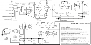
Assume I'll be using either Antek AS-1T230, AS-1T250 or AS-1T275 all of these are 100VA at 230, 250 or 275 volts. Antek only has a 240V in their 50VA. All have the same winding schema. I made the revisions to the diagram based on everyone's comments and will upload that in the next post too.
Last edited:
6J6:
A 6J6 is by nature a dual triode with common cathodes. The only way to use individual self bias of two 6J6 triodes is to use 1/2 of each of two 6J6 tubes.
Go back to the single self bias resistor and single bypass capacitor (original resistance and original capacitance), and live with a single 6J6's common cathodes.
Plug one in, and (carefully) measure the voltage drop across the 36 Ohm plate resistors.
Measure the voltage match or mismatch.
I would not worry about a slight mismatch, but if you are worried, then you can purchase a few 6J6 tubes.
Then repeat the measurements with another 6J6 . . .
6BX7:
I used 6BX7 output tubes in a push pull amp that I loaned out to a friend, he loved it.
And I like the idea of a parallel single ended 6BX7 too.
Last edited:
OK, let's work with the AS-IT230,
2 ea, 6.3 VAC outputs
2 ea., 230 VAC outputs.
Parallel the 230 VAC outputs, for 440 mA potential supply current. Working with your full-wave bridge part-sand-part-vacuum design:
This, of course, all depends on the Grand Simplification of napkin-guessing the both-channels taking up about 200 mA between them. Dunno if that is right nor not, yet. Doesn't feel terribly off-key though.
________________________________________
I guess this then points us back to analyzing — in detail — the quiescent current flow of 'LEFT' say. Right?
(I'm not going to try to list it all out... this takes a lot of time!)… but I calculate 85 mA per channel, quiescent current. Not a bad guess at 100 mA.
So, the above would be resistor values.
⋅-=≡ GoatGuy ✓ ≡=-⋅
2 ea, 6.3 VAC outputs
2 ea., 230 VAC outputs.
Parallel the 230 VAC outputs, for 440 mA potential supply current. Working with your full-wave bridge part-sand-part-vacuum design:
V+ PEAK = 230 × 1.414 - 25 (vacuum)
V+ PEAK = 300 V
V- PEAK = 230 × 1.414 - 3 (diode)
V- PEAK = 323 V
VMEAN DC PEAK = 312 V more or less
R101 V-loss = 15 V (design point)
L102 R-DC = 63 Ω (Hammond 193H, $85, 300 mA max, 10 H)
R103 V-loss = 15 V (design point)
R104 V-loss = 10 V (design point)
IQ est = 200 mA
VL 102 loss = I R
VL 102 loss = ²⁰⁰⁄₁₀₀₀ × 63
VL 102 loss = 12.6 V
VB+ = 312 - (15 + 15 + 12.6 + 10)
VB+ = 259 VDC
Let's turn those design points back into R-TBDs. V+ PEAK = 300 V
V- PEAK = 230 × 1.414 - 3 (diode)
V- PEAK = 323 V
VMEAN DC PEAK = 312 V more or less
R101 V-loss = 15 V (design point)
L102 R-DC = 63 Ω (Hammond 193H, $85, 300 mA max, 10 H)
R103 V-loss = 15 V (design point)
R104 V-loss = 10 V (design point)
IQ est = 200 mA
VL 102 loss = I R
VL 102 loss = ²⁰⁰⁄₁₀₀₀ × 63
VL 102 loss = 12.6 V
VB+ = 312 - (15 + 15 + 12.6 + 10)
VB+ = 259 VDC
R101 = E/I
R101 = 15 ÷ 0.200 = 75 Ω (at 1.13 W)
R103 = E/I
R103 = 15 ÷ 0.200 = 75 Ω (at 1.13 W)
R104 = E/I
R104 = 10 ÷ 0.200 = 50 Ω (at 0.50 W)
R101 = 15 ÷ 0.200 = 75 Ω (at 1.13 W)
R103 = E/I
R103 = 15 ÷ 0.200 = 75 Ω (at 1.13 W)
R104 = E/I
R104 = 10 ÷ 0.200 = 50 Ω (at 0.50 W)
This, of course, all depends on the Grand Simplification of napkin-guessing the both-channels taking up about 200 mA between them. Dunno if that is right nor not, yet. Doesn't feel terribly off-key though.
________________________________________
I guess this then points us back to analyzing — in detail — the quiescent current flow of 'LEFT' say. Right?
(I'm not going to try to list it all out... this takes a lot of time!)… but I calculate 85 mA per channel, quiescent current. Not a bad guess at 100 mA.
So, the above would be resistor values.
⋅-=≡ GoatGuy ✓ ≡=-⋅
ALERT … wrong WATTAGE for those resistors…
P = IR or (I²R) or (E²/R) so
⋅-=≡ GoatGuy ✓ ≡=-⋅
P = IR or (I²R) or (E²/R) so
R101 = E/I
R101 = 15 ÷ 0.200 = 75 Ω (at 3 W use 5 W for safety)
R103 = E/I
R103 = 15 ÷ 0.200 = 75 Ω (at 3 W use 5 W for safety)
R104 = E/I
R104 = 10 ÷ 0.200 = 50 Ω (at 2 W use 5 W for safety)
Sorry, folks. I make mistakes too… sigh…R101 = 15 ÷ 0.200 = 75 Ω (at 3 W use 5 W for safety)
R103 = E/I
R103 = 15 ÷ 0.200 = 75 Ω (at 3 W use 5 W for safety)
R104 = E/I
R104 = 10 ÷ 0.200 = 50 Ω (at 2 W use 5 W for safety)
⋅-=≡ GoatGuy ✓ ≡=-⋅
6J6:
A 6J6 is by nature a dual triode with common cathodes. The only way to use individual self bias of two 6J6 triodes is to use 1/2 of each of two 6J6 tubes.
Go back to the single self bias resistor and single bypass capacitor (original resistance and original capacitance), and live with a single 6J6's common cathodes.
Plug one in, and (carefully) measure the voltage drop across the 36 Ohm plate resistors.
Measure the voltage match or mismatch.
I would not worry about a slight mismatch, but if you are worried, then you can purchase a few 6J6 tubes.
Then repeat the measurements with another 6J6 . . .
6BX7:
I used 6BX7 output tubes in a push pull amp that I loaned out to a friend, he loved it.
And I like the idea of a parallel single ended 6BX7 too.
Duhhhh! I should have seen that since the tube basing was right in front of me. I have a bunch of 6J6.
- Status
- This old topic is closed. If you want to reopen this topic, contact a moderator using the "Report Post" button.
- Home
- Amplifiers
- Tubes / Valves
- Please criticize my derivative design for a computer desk amp