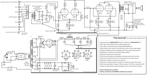
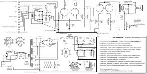
OK here is the updated schematic. The plate resistance of 6BX7 is listed as 1300 so I indicated using the OneElectron UBT1 at 1600 ohms for the OPT. Hopefully this will be ok here? Because I already have two UBT1 transformers. I hope you guys dont mind I mentioned your id's as helping on the schematic, who knows maybe someone else will try this one out.
Any other suggestions welcomed.
Any other suggestions welcomed.
Attachments
If the fan runs ok with about 7V, then use 4 diodes in a bridge configuration with a single capacitor, instead of using the voltage doubler.
You do want cooling, but you do not want the fan to be a noise maker.
Just something to try when you get the amp up and running.
You do want cooling, but you do not want the fan to be a noise maker.
Just something to try when you get the amp up and running.
If the fan runs ok with about 7V, then use 4 diodes in a bridge configuration with a single capacitor, instead of using the voltage doubler.
You do want cooling, but you do not want the fan to be a noise maker.
Just something to try when you get the amp up and running.
I was thinking of that too when I first added the fan. I may just look for the worlds smallest 12V wall wart and mount that on the ac side inside the case and forget about the doubler.
Actually 3ASummer's approach is better.
What you want is an already-know-to-be-quiet fan, run at sub-nominal speed. Making it quieter … and moving still-enough, but less air. Its a good idea. You might want to substitute in very low VF Schottky diodes to get closer to 8 V. It'll still be enough. No harm comes to a super-quiet fan run at sub-nominal rotating speed.
⋅-=≡ GoatGuy ✓ ≡=-⋅
PS -- careful about wall-warts. They bring potentially yet-another-source-of-hum-and-buzz inside the amp!
Actually 3ASummer's approach is better.
What you want is an already-know-to-be-quiet fan, run at sub-nominal speed. Making it quieter … and moving still-enough, but less air. Its a good idea. You might want to substitute in very low VF Schottky diodes to get closer to 8 V. It'll still be enough. No harm comes to a super-quiet fan run at sub-nominal rotating speed.
⋅-=≡ GoatGuy ✓ ≡=-⋅
PS -- careful about wall-warts. They bring potentially yet-another-source-of-hum-and-buzz inside the amp!
Will do, I was thinking he was referring to diode noise getting into the filaments. I have run fans at lower voltage, you just need find a brand that will start spinning at that voltage from a dead stop.
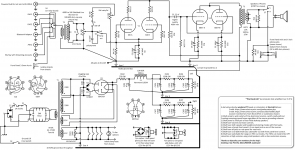
Also, not fan related, would a decoupling capacitor benefit anywhere here with only two stages?
Two smallish things…
I personally would duplicate the TBD resistor-and-capacitor-chain following the 10 Hy choke: keep the capacitor values, double the resistances; (this keeps the voltage drop the same, but actually increases filtering). You don't need to show this on the diagram, but write it as a note …
Not sure where you'd want the decoupling capacitors.
Less important if you do the above paragraph's recommendation.
... you might want to label the TBD resistors ... then say something like, 'between R31 and R32...' ... ... ...
Anyway… there you go.
⋅-=≡ GoatGuy ✓ ≡=-⋅
Last edited:
Two smallish things…
I personally would duplicate the TBD resistor-and-capacitor-chain following the 10 Hy choke: keep the capacitor values, double the resistances; (this keeps the voltage drop the same, but actually increases filtering). You don't need to show this on the diagram, but write it as a note …
Not sure where you'd want the decoupling capacitors.
Less important if you do the above paragraph's recommendation.
... you might want to label the TBD resistors ... then say something like, 'between R31 and R32...' ... ... ...
Anyway… there you go.
⋅-=≡ GoatGuy ✓ ≡=-⋅
Thanks I just had an "ah ha" moment finally understanding those kind of power supplies that duplicated the filter chains for each channel. Essentially they are in parallel so you have to double the resistances. A nice design pattern we went through to calculate both channels combined, then simply split it L/R. This is very cool, learning a lot! I am going to post a rev 4 soon.
PS — I'll just add, that it is a real pretty drawing, friend.
Tho' they're really convenient to key in, I truly detest all the twiggy random-line-crossing schematics that sim-software packages squirt out. Rarely do they have the functional guidance that a well drawn, manually drawn schematic has, such as yours.
I'm especially pleased that you didn't use European least-common-denominator rectangles for resistors and black boxes for transformer/choke windings. They are, to me, the same as comparing a petrol filling station fast food burger to a well made charcoal grilled masterpiece. Caricatures. Simplistic pre–1980 approximations that could be easily computer generated by graphics programming simpletons. Keep the squigs, saith I!
Ahem.
End of rant.
Sheepish goat.
Bravo!
⋅-=≡ GoatGuy ✓ ≡=-⋅
PS — I'll just add, that it is a real pretty drawing, friend.
Tho' they're really convenient to key in, I truly detest all the twiggy random-line-crossing schematics that sim-software packages squirt out. Rarely do they have the functional guidance that a well drawn, manually drawn schematic has, such as yours.
I'm especially pleased that you didn't use European least-common-denominator rectangles for resistors and black boxes for transformer/choke windings. They are, to me, the same as comparing a petrol filling station fast food burger to a well made charcoal grilled masterpiece. Caricatures. Simplistic pre–1980 approximations that could be easily computer generated by graphics programming simpletons. Keep the squigs, saith I!
Ahem.
End of rant.
Sheepish goat.
Bravo!
⋅-=≡ GoatGuy ✓ ≡=-⋅
Thanks! I'm resuming this hobby at 64 from where I left it off at 25, (life happened in between), but now we have computers and Visio. My brain is still tuned to zigzag resistors, curve plate caps to indicate outer foil, transformers with coils, etc. old school. I'm collecting and making many Visio shapes with this my first drawing. As I need them I'm making actual tube bases from the images in the RCA tube substitution manual as reusable shapes. Tube bases are actually pretty easy I just clip the image from the substitution manual add a text box for the tube number, group it and drag that to my tube bases stencil. I add connection points to the pins in case anyone wants to actually use the base diagram as the tube in the schematic. I prefer seeing a generic tube element in the diagram, but include the basing diagram as a legend. There are over 800 tube base diagrams but I expect only 50 or so are widely needed.
I hope to share a zip file of Visio shapes here in the future if anyone uses Visio.
The 6BY5 recommended current limit is 175 mA, so you might have to user something else if your total current is too high.
The 6BY5 recommended current limit is 175 mA, so you might have to user something else if your total current is too high.
Thanks for the heads up. I figure when I have all the parts here I'll run it with one channel, and measure the total draw on that tube. Hopefully that number will be 40% of the limit or less. If its not then there are plenty of different compactron dampers out there, or I'd have to use a dual rectifier tube. I'd have to go back to the drawing board!
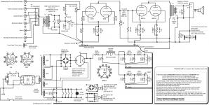
A tiny FYI/critique: the input transformer has a laminated iron core, just like the others. The other thing is that 'by convention', the core extends all the way to the end of the coil representations. I mention this 'cuz of the output transformer's 'iron' is short-of-the-mark.
Since you're developing your parts library, might as well get those right, right?
And some annotation, per attached, in red-brown (yours in black, of course)
… and more to cover all devices, even the kilovolt snubbers.
GG
PS ... also attached, example of how I 'manually draw', as well. I use Adobe Illustrator.
Attachments


Last edited:
A tiny FYI/critique: the input transformer has a laminated iron core, just like the others. The other thing is that 'by convention', the core extends all the way to the end of the coil representations. I mention this 'cuz of the output transformer's 'iron' is short-of-the-mark.
Since you're developing your parts library, might as well get those right, right?
And some annotation, per attached, in red-brown (yours in black, of course)
… and more to cover all devices, even the kilovolt snubbers.
GG
Geeze I forgot the core, no problem my transformer shapes are interchangeable mix and match separate coils and cores so you can make any transformer, then group it up. I know I have to number all the components yet. I will update it later. Probably keep this same thread all the way into the build too.
Windcrest77,
I agree with GoatGuy, you are drawing good looking schematics.
Keep it up.
Thanks again, it's fun once you get used to the software.
Yes, 6A3 is right! I was completely overlooking that the 6J6/ECC91 is a miniature double triode with a common rectangular cathode and the grids and plates arranged at both sides of it. Hence, current balancing isn't possible at all.
Best regards!
An interesting thought I just had about common cathode tubes... Sure you can't balance them, but if you test for and select a perfectly balanced tube, it's going to stay balanced forever right? Because there is only one cathode wearing out. This could be one reason 6J6 was used in instrumentation equipment maybe.
- Home
- Amplifiers
- Tubes / Valves
- Please criticize my derivative design for a computer desk amp