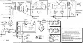
Sorry to resurrect this so soon, but I'm having a hard time figuring out if I have enough current to power my filaments or not. I revised the design again to offer a DC option for the 6J6 using the simplest DC supply possible (bridge and capacitor). In case I'm hearing hum in near field speakers and as a last resort need DC filaments. However I've read that this bridge/cap will require double the draw due to power factor of .5. Here are the ratings of all my filaments, I have two 3A windings, not sure if the damper can share its winding or not. Plus I'll need a little extra for the fan (also on a bridge and cap). I already moved the pilot lamp to the damper winding. And as you can see using AC I'm already over the 3A winding with the 4 tubes.
How do you think I can arrange the filaments here using this torroid and still offer a DC option? Do you think I need a different transformer? Parallel the 6.3V windings?
6J6 0.45A x 2 = 0.90A (AC) or 1.8A DC using simple bridge and capacitor due to power factor loss.
6BX7 1.5A x 2 = 3.0A
6CG3 1.8A
Total
5.7A AC
6.6A with 6J6 on DC!
Attachments
Last edited:
The Damper diode rectifier's filament is elevated to high voltage B+.
It must have its own Separate 6.3V winding.
None of your other tube filaments can have hundreds of volts B+ on them.
Causes of Hum . . .
Steel chassis conducts magnetic fields from power transformer and B+ choke to:
Interstage transformers
Output transformers
Use aluminum chassis. Keep space from power transformer and choke versus placement of interstage and output transformers.
Ground loop caused by Capacitor input B+ filter . . . keep that loop local, do not bring it out to the central ground point right away. Use short wiring from B+ center tap to the negative of the input cap. Next, a wire from the input cap negative to the 2nd cap negative. Then, a third wire from the 2nd cap negative to the 3rd cap negative, and then a 4th wire from the 3rd cap negative to the 4th cap negative. I see this is 'almost' what is shown as star B, but not accurately.
Now join star B to star C.
The advantage of the EMI input filter is that is gets rid of common mode noise from Hot and Neutral going to the power transformer primary (but the power transformer gets rid of that automatically anyway).
The dis-advantage of the EMI filter is that it puts common mode noise on the Star A ground (now you know why I do not use EMI filters on my amplifier power inputs).
In the US, where we have most house wiring as 3 wire Hot, Neutral, and Ground, the IEC input socket should have ground connected to the single point that will be the chassis ground point.
Star D is correct, and so is the insulated RCA input connector returns, they merely have to connect only to star D.
Now that Star B and Star C are connected together, connect from there to the one chassis ground point.
Now connect Star A to the chassis ground point.
Consider Star A, B, C, D to be sub-star points, and the central ground at the chassis where they all join to be the final Star ground.
A large diameter wire ground bus is a ground loop waiting to happen. Consider that currents through the sub-mili Ohm bus will become
voltage differentials along the bus. And at high frequencies, the wire inductance raises the impedance along the wire even higher.
Unless you have a 6J6 with leaky filament to cathode interface, you should not need DC filaments. The same goes for the 6BX7.
In the US, I do not like the ground lift switch on the power input circuit.
If the power transformer primary, secondary, or the output transformer primary short to chassis, you have a live chassis.
I have seen that.
Prevent the surviving spouse syndrome.
Most US turntables, phono preamps, tuners, CD players, etc. have 2 wire ungrounded power plugs. Some of them have switcher power supplies, some have linear supplies. Sometimes in order to reduce ground loops, you may have to reverse the way the plug is inserted in the outlet or power strip.
Sometimes a wall switcher supply that powers a phono preamp may have to be replaced with a lower noise version.
I regularly get 100uV or less hum and noise on my amplifier output transformer secondary.
Attention to details usually gets you there.
Your mileage may vary.
Last edited:
The Damper diode rectifier's filament is elevated to high voltage B+.
It must have its own Separate 6.3V winding.
None of your other tube filaments can have hundreds of volts B+ on them.
Causes of Hum . . .
Steel chassis conducts magnetic fields from power transformer and B+ choke to:
Interstage transformers
Output transformers
Use aluminum chassis. Keep space from power transformer and choke versus placement of interstage and output transformers.
Ground loop caused by Capacitor input B+ filter . . . keep that loop local, do not bring it out to the central ground point right away. Use short wiring from B+ center tap to the negative of the input cap. Next, a wire from the input cap negative to the 2nd cap negative. Then, a third wire from the 2nd cap negative to the 3rd cap negative, and then a 4th wire from the 3rd cap negative to the 4th cap negative. I see this is 'almost' what is shown as star B, but not accurately.
Now join star B to star C.
Thanks, I should have flexibility on the wiring and placements, I can depict the star changes here.
But right now I think I'm over the top on the filament current draw, especially since I cant share the damper winding. I tied the filament to the cathode on the damper to protect that, but in so doing i think I'm now out of filament current to go around! So I probably need to figure out a new transformer, sadly this one is ordered and would have fit perfectly.
Correct Star B was meant to be one physical place. The jumper is where I go to the 2nd floor chassis, it will be a "two story" wooden box with power chassis on bottom and amp chassis somewhere above at top with any amount of space between. OPT's will hang upside down from the top chassis inside the box, input transformer on top. Torroid is inside the bottom hammond chassis, choke on top of it, OPT's above will have space from choke. I stil need to draw what I want to do. But basically two stories to reduce the footprint size, I have room to go "up" but not "out" on my desk.
Windcrest77,
Thanks.
I did more edits on my post, added more comments (28 minutes total, just under the forum's 30 minute edit/add limit).
I forgot to add that I use a very large capacitance in the 2nd capacitor to knock the hum of the B+ down.
That 2 stage vertical amp hurts my head. I do not even want to think about how to keep the hum down for an architecture like that.
But it should be nice when completed.
Last edited:
Windcrest77,
Thanks.
I did more edits on my post, added more comments (28 minutes total, just under the forum's 30 minute edit/add limit)
That hurts my head. I do not even want to think about how to keep the hum down for an architecture like that.
Thanks for your time on that! Its basically separate power and amp chassis but not side by side on a table. More like if you were suspending the amp chassis above the power chassis. So there will be great distance between power/choke and OPT/line in xformer. Maybe 12 inches of spacing if I put the OPTs on the very top too.
Sadly I'm still over 3A on my filaments even using all AC, which I will definitely do as the first cut. I'm abandoning DC filament option too much trouble, it was a passing thought.
2 6J6 = .90A
26BX7 =3A
So 3.9A I'm going to need a transformer with 4 or 5 amps filament. I'd have that if I didnt use the damper tube, but I kinda like that part. Or I install a small 6.3V xformer for that tube then parallel the two on the torroid for 6A.
windcrest77,
Caution!
1. One more time . . . You have to use a separate 6.3V transformer for the damper diode.
That damper filament has B+ on it.
. . . Connecting any of the 6J6's and/or 6BX7's filaments to that same 6.3V will destroy those tubes.
2. It has nothing to do with the amp ratings of the filament secondaries; and it has nothing to do with the current draw of those filaments on those secondaries.
1. and 2. are totally different problems.
3. Oh! . . . I stand corrected.
The 6CG3 damper diode has a separate cathode connection.
But just be sure to correct your schematic. If you connect the filament and cathode together as in the schematic, then a common 6.3V filament winding with the other tubes Will destroy the other tubes.
4. Do not parallel different 6.3V transformers that are different models. Even if you get the phase right, the voltages may not match exactly.
A few millivolts difference in voltage with milliohm windings makes for Amps of currents between the secondaries, even before the filaments are connected.
It is so hard to put all the smoke back in.
Last edited:
windcrest77,
Caution!
Thanks again! Late today I'm going to take all this in, make sure my total heater currents are within the specs of this transformer, make revisions and upload again. I think I've found an easy way to power the damper and other filaments without doing any of the mistakes mentioned by just adding a tiny 2A tranny for the damper and paralleling the Antek heater windings for the other 4 tubes.
Later in the week I want to learn sketch up or some other 3D program to post what kind of wooden box I'm thinking of too. Basically I want a tall/narrow table radio, (in mid-century modern style), probably walnut, but without the speakers and tuner!
Made some simplifications and paralleled both primaries on the Antek.
Also my filaments are at about 3.9A for the 6J6 and 6BX7 combined. But the other 6.3V winding is still well under 3A. Can I get by with running the filaments this way as long as the 100VA of the transformer is not being exceeded? If not, am I safe to detach the filament of the 6GC3 from its cathode at this voltage and not exceed the cathode/filament rating? So I can just parallel the two filament windings and have plenty of amps to run all the tubes from the parallel windings.
I'm a little confused on how to read the data sheet for heater/cathode limit for the 6GC3 here:
https://frank.pocnet.net/sheets/123/6/6CG3.pdf
Attachments
6CG3:
Heater Negative with Respect to Cathode:
That means the Cathode is more positive than the heater (filament).
DC Component . . . + 900 Volts
(Cathode can be no more than + 900VDC, when the filaments are at or near to 0 volts).
You do have a lot less than + 900VDC there.
Just make sure that your 6CG3 meets specification (good tube).
Even so, I recommend using a separate 6.3V filament winding for the 6CG3.
If you connect the other tubes and 6CG3 filaments to the same filament power,
Then what if the tube goes bad and shorts from filament to cathode?
That would apply all the B+ voltage charge from the B+ capacitors directly to the
6J6’s and 6BX7’s 6.3V filament windings.
You have a Pseudo center tap to ground (you have a 200 Ohm potentiometer there).
But I would not trust that potentiometer after B+ is connected to it. Those caps can put out tremendous current (even if only for a small amount of time)
And you might also ruin all the 6J6 and 6BX7 filament to cathode insulations too.
A second reason to use separate filament supplies is that the 6CG3 B+ transient noise and hum might transfer from its cathode to filament, and from there to the other tubes filaments.
Someone who has some experience using damper tubes might relate what they know about any hum and noise issues when using common 6.3V filament windings.
I would be surprised if you need DC filaments for the 6J6 and for the 6BX7.
If this was for a headphone amplifier, then maybe.
But for a horn loaded speaker, I hope not.
Using two stage amplifiers, single ended and push pull, and with indirectly heated cathodes, I get 100uV or less hum and noise, but I have to pay attention to all the other details of the amplifier to get it that low.
Last edited:
1. You have 3.9 amps on one 3A winding, I do not like that.
Then, you are adding the fan to that current draw too.
2. If your fan is enclosed and safe from touch, and if the fan is safe to run at B+ without arcing to the chassis, then power the fan rectifiers from the 6CG3 filament winding. The fan is floating, and gets the correct voltage, it does not have B+ applied 'across' the fan.
3. If you have the room, add a small 6.3V 1A transformer to power the 6J6 tubes.
Then the other 3A winding can power the 6BX7s.
Do 2. and 3. above, and all is well.
Last edited:
1. You have 3.9 amps on one 3A winding, I do not like that.
.
Thanks again, all the things you mentioned I thought might be issues but now I know what's best practice, noise, failure of the damper, overload, etc. I do have another Antek 50VA 6.3V transformer, it's nice and small. I'm going to run the 6J6 tubes on that one with the pilot lamp. I'll run the 6BX7 tubes all alone where they are that's exactly 3A. For failure mode reasons I'll leave the filament and cathode tied together, but now I finally understand how to read that part of the data sheet and know that I could float the filament. I'll put the fan over with the 6j6 tubes on the separate transformer and fuse the fan feed with a smaller fuse in case a diode fails short there. Having the 6J6 on a dedicated transformer might be an advantage noise wise later anyway. Thanks again, moving along. I'll most likely breadboard the PS first so I'll know my exact voltage empirically. Then I'll tweek the load line finding best operating points with that voltage for THD then adjust some cathode resistors to get my operating point.
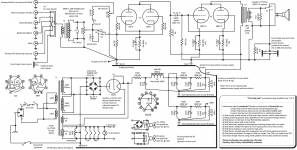
Added a small torroid dedicated to the filaments as those were overloading the 3A winding on the main transformer by 900ma. That may not have been such a big deal according to Antek but it would have starved those filaments voltage-wise a little. Added some protection fuses. T1, T2 and T3 have shields so I indicated their ground points. Replaced the humdinger with just two resistors for virtual heater ground. DC options if used now have a dedicated fused winding and will ground on their DC side now that they no longer share the filament winding.
Attachments

The 6CG3 filament takes 1.8A. I am not sure what the purpose of a 2.5A slow blow fuse there is. Yes, the filament draws lots more than 1.8A until the filament warms up.
But are you worried that the filament will short to itself during normal operation?
Putting a rectifier and capacitor filter to drive a fan, or a USB circuit, on the 6J6 filament transformer might cause interference in the 6J6 cathode circuit, maybe not.
A few things I do in my amplifiers to keep parts cool:
I have holes in the bottom cover of the chassis, and there are some holes in the top of the chassis (I know that does not look neat). But free air flow is free cooling. Just a well perforated bottom plate helps, if you do not want to put holes in the top.
I use higher wattage rated self bias resistors for the output stage; typically 5 X the actual watts dissipated. The larger part has more surface area, for free air cooling.
I use good physical spacing of hot items, like tubes spaced from each other, and from
top-of-the-chassis capacitors.
I try and use 105 degree rated capacitors, not 85 degree rated.
Some of my amplifiers use cap input B+, and solid state B+ diodes. At power-up, the inrush current is determined by the discharged B+ capacitor initial charging current, and by the low resistance cold filaments of the tubes. I use a fast-blow fuse in the primary circuit that is just large enough so that it does not blow at power-up, and does not blow during a
hot-start (amp running and warm, power goes out and B+ discharges, and then the power comes on again, with hot tube filaments).
Then, I also put a slow-blow fuse in series with the fast blow fuse, that is just large enough so that it does not blow when the amp is running warm, or during high volume music passages if it is a push pull amp.
An example of some of those amps is 1 or 1.25A fast blow fuse, in series with a 0.5A or 0.6A slow blow fuse.
the idea is to protect against catastrophic failures, and against a tube that gets gassy and has thermal run-away or other similar incident.
Last edited:
The 6CG3 filament takes 1.8A. I am not sure what the purpose of a 2.5A slow blow fuse there is. Yes, the filament draws lots more than 1.8A until the filament warms up.
But are you worried that the filament will short to itself during normal operation?
I know filaments fail open so a fuse is inherent, but in this case the filament and cathode are tied I wanted to protect the tranny from that kind of short.
Putting a rectifier and capacitor filter to drive a fan, or a USB circuit, on the 6J6 filament transformer might cause interference in the 6J6 cathode circuit, maybe not.
As you can see I moved the 6J6 and 6BX7 to a dedicated torroid, so they no longer share the winding with the DC options.
A few things I do in my amplifiers to keep parts cool:
I have holes in the bottom cover of the chassis, and there are some holes in the top of the chassis (I know that does not look neat). But free air flow is free cooling. Just a well perforated bottom plate helps, if you do not want to put holes in the top.
I use higher wattage rated self bias resistors for the output stage; typically 5 X the actual watts dissipated. The larger part has more surface area, for free air cooling.
I use good physical spacing of hot items, like tubes spaced from each other, and from
top-of-the-chassis capacitors.
I try and use 105 degree rated capacitors, not 85 degree rated.
The case I'm going to design is going to be all about cooling, the top plate will "float" on hidden standoffs so heat can chimney up and out under the floating top plate. Exhaust fan in back, air entry points in front, much like a tower computer case. But made of wood, nice looking (vilylsavor inspired). dimensions approx: 7W x 7D x 16H (inches). 6J6 and 6BX7 on top along with the small line xformers (probably the numetal cased Sowter cans that mount on a bolt stud, still deciding on the line xformer brand). But the damper and all other parts will be enclosed inside the box. I really need to start drawing up the case, probably just in 2D. Yes it will have some kind of active cooling and convection cooling.
Some of my amplifiers use cap input B+, and solid state B+ diodes. At power-up, the inrush current is determined by the discharged B+ capacitor initial charging current, and by the low resistance cold filaments of the tubes. I use a fast-blow fuse in the primary circuit that is just large enough so that it does not blow at power-up, and does not blow during a
hot-start (amp running and warm, power goes out and B+ discharges, and then the power comes on again, with hot tube filaments).
Then, I also put a slow-blow fuse in series with the fast blow fuse, that is just large enough so that it does not blow when the amp is running warm, or during high volume music passages if it is a push pull amp.
An example of some of those amps is 1 or 1.25A fast blow fuse, in series with a 0.5A or 0.6A slow blow fuse.
the idea is to protect against catastrophic failures, and against a tube that gets gassy and has thermal run-away or other similar incident.
Thanks for the ideas on protection, much of that I'll add empirically in testing. But I promise to keep the schematic updated! Too many project here I want to build but cant find the least buggy schematic so I decided to just do my own project. It's actually more fun because its more problems to solve myself and friends here.
- Home
- Amplifiers
- Tubes / Valves
- Please criticize my derivative design for a computer desk amp