Feedback.The tubes are the same in both versions. What they probably did to reduce that much the STN?
@ ctechdx: There's obviously no rectification nor regulation for the heaters onboard. So AC heated. The high voltage audio section is of course DC.
Removing the transformers from the board probably won't help much. The noise is probably mostly radiated 50hz due to heavy currents running through the pcb to the heaters.
The version 2 has what looks like a low voltage rectified and regulated supply. It seems awfully small for the almost 3A required but who knows...
@audiowize: because many headphones are awfully efficient. What is of interest is the noise floor related to actual quiet listening levels, not vs max output. 2V is absolutely deafening with something like a pair of HD650.
@ ctechdx: There's obviously no rectification nor regulation for the heaters onboard. So AC heated. The high voltage audio section is of course DC.
Removing the transformers from the board probably won't help much. The noise is probably mostly radiated 50hz due to heavy currents running through the pcb to the heaters.
The version 2 has what looks like a low voltage rectified and regulated supply. It seems awfully small for the almost 3A required but who knows...
.
Do you think changing the low voltage transformer and making It rectified and regulated would improve the STN? Any suggestion on How to do this? Should i need a New transformer and another board to regulate voltage before deliver to the valhallas board?
Do you think changing the low voltage transformer and making It rectified and regulated would improve the STN? Any suggestion on How to do this? Should i need a New transformer and another board to regulate voltage before deliver to the valhallas board?
Again, you need a new chassis and to start from scratch. To even test the effectiveness of this would require work that's likely to destroy the PCB.
A regulated DC heater should not be required, but it's tough to "twist" AC heater wires when you're using a PC board.
A transformer with an AC load can be smaller than a transformer with a capacitive input DC supply, so you'd need a new one. But I really don't see how you could fit a bigger transformer, a diode bridge, some caps and regulation (not necessarily required) in there. It would have to be built in an outside box, power brought in and injected at the right point (which might require to unsolder the current low voltage transformer).
I would take very seriously audiowize's warning: it's not a trivial mod and if it's not very clear to you how to do that, the chances to end up with a non functional amp are high. It also requires you to wire properly mains connected components and, again, if you're not very clear on that, it can be dangerous. It's not just about swapping parts.
edit: another thing: I cannot identify any part in there that would serve to elevate the heaters with a DC bias. Given the likeliest topologies for this amp, that oversight might not help with noise.
Last edited:
Returning to the possible modding to be made I'd replace the PSU capacitors with Nichicons KX, thay are good without spending a fortune. In case I would change the tube socket too, being very close to each other and resting on the metal platform...I suggestion could be to raise them with this socket:
Attachments
Returning to the possible modding to be made I'd replace the PSU capacitors with Nichicons KX, thay are good without spending a fortune.
Is their ripple current rating sufficient? What are you trying to accomplish by doing this? Is there a reason for doing this? What's in the amp now? Have you modeled the power supply and looked up the specs for what's in the amp now so you can understand what the cap requirements are?
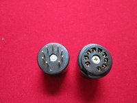
Same as above. Why replace the tube sockets? What is the goal? Some other 9 pin PCB mount sockets won't sit in those same holes. What will you do when the traces fall off the board when you're reworking it?In case I would change the tube socket too, being very close to each other and resting on the metal platform...I suggestion could be to raise them with this socket:
Why do you want to use a socket saver? How much tube rolling are you going to do?
Is their ripple current rating sufficient? What are you trying to accomplish by doing this? Is there a reason for doing this? What's in the amp now? Have you modeled the power supply and looked up the specs for what's in the amp now so you can understand what the cap requirements are?
Same as above. Why replace the tube sockets? What is the goal? Some other 9 pin PCB mount sockets won't sit in those same holes. What will you do when the traces fall off the board when you're reworking it?
Why do you want to use a socket saver? How much tube rolling are you going to do?
I begin from the end, I have a friend of mine runnin this amp and told me (a little con but I don't mean a grief) that it has the tendence to heat with such a disposition of the valves itselves. That was an observation, maybe depending on (intensive) use or not.
As for the capacitors I tried them and seems to sound "smoother" so they could tame the "character" of the Valhalla, if pleased so. For the specs and data I'd remand here:
NICHICON KX
LKX2G331MESA50 Nichicon | Mouser Italia
....
However, if I may say, we are here to speak freely and give personal opinions, which may or may not be appreciated, which can be scientifically supported or not. After all, what should like is in the ear as well as by the numbers. As far as I am concerned with tube rolling, I did it, but without hiding I don't say that I am an expert, on the contrary, however, I consider myself a precise person who uses common sense...
However, if I may say, we are here to speak freely and give personal opinions, which may or may not be appreciated, which can be scientifically supported or not. After all, what should like is in the ear as well as by the numbers. As far as I am concerned with tube rolling, I did it, but without hiding I don't say that I am an expert, on the contrary, however, I consider myself a precise person who uses common sense...
I would take very seriously audiowize's warning: it's not a trivial mod and if it's not very clear to you how to do that, the chances to end up with a non functional amp are high. It also requires you to wire properly mains connected components and, again, if you're not very clear on that, it can be dangerous. It's not just about swapping parts.
Yes i understand its not a simple mod, but i think its not that difficult either. I'm noobie on electronics, but studying a lot, I believe I can handle this. I gonna make everything very carefully and also will ask help here always I have a doubt.
About the space I gonna move this circuit to a 3U 19" rack. Then will be a lot more space for the transformer and also a rectifier board.
I want to try! What do you think I will need to begin with this mod? I know a guy who build good power transformers. I can ask him to build the transformer, and the rectify board I will need some suggestion. Do you know some project that would fit for these heaters?
edit: another thing: I cannot identify any part in there that would serve to elevate the heaters with a DC bias. Given the likeliest topologies for this amp, that oversight might not help with noise.
This part i didn't understand well what you mean. Could you please explain me this better?
Thanks
Folks,
The valhalla is made to work with 115v from the outlet. But here in my city the outlet deliver 127v. Is this ok for a tube amp? Does the amp transformer deal with that difference and delivery the right voltage to the circuit? Or should I do something to regulate that AC voltage?
thanks
The valhalla is made to work with 115v from the outlet. But here in my city the outlet deliver 127v. Is this ok for a tube amp? Does the amp transformer deal with that difference and delivery the right voltage to the circuit? Or should I do something to regulate that AC voltage?
thanks
Line voltage that's 8% high isn't all that bad. You should call your power utility to discuss why your line voltage is so high.
No, its ALL right... I live in Brazil and here in my city the standard voltage is 127v. But the valhalla was made and USA, 115v standard. Does It cause any changes in Valhala's voltage? Should I try to regulate the voltage?
Ok thanks!
Folks please help me with another noobysh question hehehe

In a tube preamp like this, what can i do to add a potentiometer to Control the gain stage? Im trying the schematics in a simulator, and It Works, the signal has incresed. But i want to Control that amount of boost that tube is adding.
Folks please help me with another noobysh question hehehe
In a tube preamp like this, what can i do to add a potentiometer to Control the gain stage? Im trying the schematics in a simulator, and It Works, the signal has incresed. But i want to Control that amount of boost that tube is adding.

- Status
- This old topic is closed. If you want to reopen this topic, contact a moderator using the "Report Post" button.
- Home
- Amplifiers
- Tubes / Valves
- Headphone tube amp components upgrade