It has been shown that in SE amplifiers, the average bias voltage (in self bias or current source bias circuits) changes as the signal drive to the output tube increases.
This is known as a shift of bias, caused by large signals.
But this bias shift is lower for a self bias R with C network, versus a current source and bypass cap network.
Just get reliable 300B tubes, do not run them near to their maximum ratings:
Max plate to filament voltage
Max plate current (different for self bias versus fixed bias operation)
Max plate dissipation
Max grid resistor spec (different for fixed bias or self bias)
Operate the tube in a more conservative manner. That will increase the number of different manufacturers tubes that will work and be reasonably reliable (like if you want to tube roll).
Trying for max power out, you have to have very capable 300B tubes, and even with that, the tube life may be reduced.
I reckon that this is caused when the input signal peaks come close to 0 grid Volts, because even if it doesn't cross the zero Volt point, some grid current begins to flow, getting bigger, the nearer the peaks of the signal come to 0 Volts.It has been shown that in SE amplifiers, the average bias voltage (in self bias or current source bias circuits) changes as the signal drive to the output tube increases.
This is known as a shift of bias, caused by large signals.
Last edited:
..<cut>
I also do not know why a 300B has to use a bias of -85V to sound good; or is -85V bias required so we can use the 300B to near its maximum output power, or consider it to be a waste?
Was that a reason given for why a 6SN7 could not drive 170V peak to peak to a 300B?
I have a JJ 300B here, that out of the box required a bias of -82V to operate at 350V, 60mA. WE originals may be different, but for someone buying today, the JJ is one of the better ones at mid-price, and a very long way better than the cheap ones.
The EMLs bias quite close to this value, as well.
Given how wide the sample-to sample variation of bias voltage, across all the 300B versions, saying that you need to swing 170V pp is actually somewhat limiting. And that is before we get to the fact that many builders run their 300Bs at 400V or even more, and need bias voltages of -90V or more.
And so to the problem with 6SN7. Driving to large peak swings takes it into regions of nonlinearity that can be observed by a casual inspection of the curves.
And the gm is so low that you need two stages to get from line level to grid-drive, which leads to multiplication of the harmonics of the first stage.
If you think this performance and sound is good - please continue using them, without risk of interference from me. This is DIY - and we must not forget the 'Y' .
But if you promote it as an answer to others, please also allow me to say that I find it (measurably and subjectively) a second-rate solution.
In the domain of measured performance, the spectrum (and sound) offered by (for example):
- EML20/30 series DHTs, choke loaded (see Vegard's Spectrum Analyser plot elsewhere on diyAudio);
- Many kinds of triodes & triode-connected pentodes with medium-high µ loaded with Ale's µ-follower;
- My own Shunt Cascode Power Valve Driver
The results speak for themselves.
I have a JJ 300B here, that out of the box required a bias of -82V to operate at 350V, 60mA. WE originals may be different, but for someone buying today, the JJ is one of the better ones at mid-price, and a very long way better than the cheap ones.
I have two sets of JJs and one set each of Liuzhou and Golden Dragon. The JJs can be driven to give a linear (within reason) 7.7 Watts at 74 mA and a V a-k of 375 V. The Liuzhous and Golden Dragons in the same setup start to round off the waveform, way before cutoff, producing only 3.5 reasonably linear Watts. So there you go.
OK, but what is the bias voltage?
The current through the Liuzhous and Golden Dragons rises to almost 80 mA with a self bias R of 1K. This probably pushes it towards cutoff sooner than the JJs at 74 mA.
With 375V and 80mA the anode burn is 30W.
This is within the specification of Pa, but with 330K of grid leak, it is at risk of runaway on a cheap 300B.
Running it at the standard 350V 60mA would need more bias voltage.
This is all experimentation with me. I'll push the limits and report results. One thing for certain is that I ain't using no Liuzhous or Golden Dragons in my final iteration. BTW, do you have any view on "bias shift"?
For sure!
Bias shift? It will shift upwards when the grid starts to leak current. This can cause the anode to burn hotter, and in turn heats the grid, and in some cases this leads to grid emission, which increases the grid leakage, and shifts the bias hotter again. this is bias runaway, and if unobserved, it can destroy the 300B.
Cheap 300Bs are vulnerable to this flaw, and care must be taken to avoid losing a good output transformer to a triode-meltdown of this kind.
Running the cheap ones at 350V 60mA helps, but if you run higher, check that the anode current is stable after an hour or more.
For sure!
Bias shift? It will shift upwards when the grid starts to leak current. This can cause the anode to burn hotter, and in turn heats the grid, and in some cases this leads to grid emission, which increases the grid leakage, and shifts the bias hotter again. this is bias runaway, and if unobserved, it can destroy the 300B.
Cheap 300Bs are vulnerable to this flaw, and care must be taken to avoid losing a good output transformer to a triode-meltdown of this kind.
Running the cheap ones at 350V 60mA helps, but if you run higher, check that the anode current is stable after an hour or more.
Is this the bias shift that happens with large signal drive?
Ah, OK that is something else.
If you drive large anode current signals through 300B, the amount of second-harmonic increases -particularly near maximum power.
Second harmonic is asymmetric waveform, so passing this current through a cathode resistor can shift the average position of the bias voltage on the 'cathode'.
If you drive large anode current signals through 300B, the amount of second-harmonic increases -particularly near maximum power.
Second harmonic is asymmetric waveform, so passing this current through a cathode resistor can shift the average position of the bias voltage on the 'cathode'.
Ah, OK that is something else.
If you drive large anode current signals through 300B, the amount of second-harmonic increases -particularly near maximum power.
Second harmonic is asymmetric waveform, so passing this current through a cathode resistor can shift the average position of the bias voltage on the 'cathode'.
Right. That's the first time I've had a good explanation of the phenomenon - thanks.
I don't think it is a serious problem for a 300B-SE, where it should be operating in full-time class A, and low distortion.
Blocking distortion (charging of the grid cap during peaks) is much more of a problem in these little SE amps, where RC coupling is used, because the grid will certainly draw current when positively overdriven, and there is no counter-balance effect , because no current flows when the grid negatively overdriven.
Blocking distortion (charging of the grid cap during peaks) is much more of a problem in these little SE amps, where RC coupling is used, because the grid will certainly draw current when positively overdriven, and there is no counter-balance effect , because no current flows when the grid negatively overdriven.
I don't think it is a serious problem for a 300B-SE, where it should be operating in full-time class A, and low distortion.
Blocking distortion (charging of the grid cap during peaks) is much more of a problem in these little SE amps, where RC coupling is used, because the grid will certainly draw current when positively overdriven, and there is no counter-balance effect , because no current flows when the grid negatively overdriven.
Crazy and all that it seems, what I'm attempting to do is raise the value of the 300B grid leak resistor without runaway. That way, using an XYS CCS in the plate/anode of the 6SN7 will give me almost the same result as using an interstage transformer. I spent almost two days researching articles on the dynamic resistance of the IXCP10M90S, and by most accounts, it is very very high at 6 mA.
Last edited:
Blocking distortion (charging of the grid cap during peaks) is much more of a problem in these little SE amps..
That's why I use -for at least a decade- FET source follower to drive -EH- 300B grid.
")
Attachments
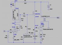
That's why I use -for at least a decade- FET source follower to drive -EH- 300B grid.
Nice design. For me though, that sort of thing will be down the road a bit. I think, if I can solve the runaway problem, 390K will be the maximum 300B Rg, because to avoid too much blocking distortion, I will have to reduce the coupling capacitor, and then I have the problem of a voltage divider between the cap and the C k-g + C miller at higher frequencies.
That's why I use -for at least a decade- FET source follower to drive -EH- 300B grid.
Could you suggest a design for use with a 300B with cathode bias using the same FET? A webpage perhaps.
- Home
- Amplifiers
- Tubes / Valves
- Problem using Hammond 126C IST