Screens may be sensitive to ripple, true.
And, the screen supply may be affected by the topology of the output stage (due to large variations in screen current).
Screen current gets large when the plate voltage drops far below the screen voltage.
The control grid is headed towards Zero Volts, so it dictates Lots of screen current.
Strong screen currents are likely to happen in true Pentode or Beam Power operation.
The plate voltage swings far, and the screen voltage is constant.
But strong screen currents are also likely to happen in Ultra linear.
Using a 40% screen tap as an example:
Start with the screen at 410V, and the plate at 400V (the 10V drop due to plate current through the additional DCR of the 60% primary winding).
Say the plate swings down to 100V, a 300V swing.
The screen swings 300V * 40% (120V swing). The screen is at 410V - 120V = 290V, and the control grid is at Zero Volts.
Check that condition on the set of plate current and screen current curves (Hint: Lots of screen current).
Then consider some screen taps that are only 25% or 33%.
That means the plate voltage moves much faster than the screen voltage.
The easiest time for the screen is when the Pentode or Beam Power tube is triode wired.
The plate voltage can not swing below the screen voltage.
An 807 Screen is rated for 300V in Beam Power mode.
But the same 807 Screen is rated for 400V in Triode wired mode.
You will not get large variations in screen current in triode wired mode, versus pentode and beam power mode.
Last edited:
The easiest time for the screen is when the Pentode or Beam Power tube is triode wired.
The plate voltage can not swing below the screen voltage.
An 807 Screen is rated for 300V in Beam Power mode.
But the same 807 Screen is rated for 400V in Triode wired mode.
But you are simply comparing apples with oranges.
It's very well know the 807 is useless for UL operation as are most of the cousins 6L6/KT66 etc because of the low internal valve gain.
The KT66 was triode wired in the original Williamson, because the screen has a higher voltage rating and because it has a lousy HF transmitter characteristic.
+
As a strapped triode it has a characteristic nigh on identical to a PX4.
Another FACT.
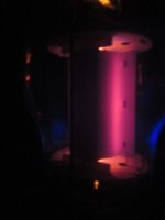
The 807 was a very advanced valve for the precise reason the Anode could be swung off into the HT stratosphere without it blowing up or flashing over, and the screen grid was fully aligned.
As a result, you can get them to hammer on with the anode glowing bright red for hours....
As a result the 807 is a paragon of virtue for screen grid current, which is why they make super efficient transmitting valves up to 50Mhz, despite being a "pinch construction".
Even driving them into a full 20V into control grid current, the thing still refused to conduct silly amounts of screen current, and remain dead linear.
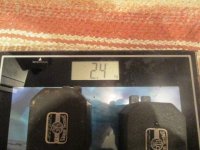
I have a pair here that run at 825V on the anodes and knock out 120W.. I'll post the pics of the so called "5kg" chokes that are supposed to be in there.
I weighed 3 UTC chokes of a similar size together and I can't get them over 3.5kg!!
Last edited:
6vheater,
You said noise and ripple of B+ tends to be cancelled in a push pull amp.
That is true.
Starting with several stages of push pull or balanced amplification:
I would caution that if the ripple is present in earlier stages, it can be amplified all the way to the output stages.
When that happens, I have seen very large common mode currents at the output stage.
And those large current variations do Rob power from the output (lower the maximum power out).
6vheater,
I have a pair of commercial hi fi Push Pull parallel EL34 amplifiers in Ultra Linear mode, that were designed for lots of power, but that design abused the 6550's capabilities, when someone decided to tube-roll the amplifier.
Large signals blew up the 6550's 10 Ohm cathode resistors (kinda hard on the
resistor, and kinda hard on the 6550).
As to 807 tubes, letting the plates glow red for a few more watts will not help a navy destroyer in the middle of the pacific when there are no more 807s on board. The captain will not be pleased.
It is a known effect, that if a ham transmission is from a country that does not have very many hams, the ham operator listening at the other end can copy the signal that is about 3 dB worse than he can normally copy (he wants to complete his "Worked all Counties" certificate).
Last edited:
6vheater,
I recently purchased my second set of matched JJ KT66 tubes from my favorite tube supplier,
EuroTubes.com (I drove over and picked them up, they are my metro area).
I really like those JJ KT66 tubes.
You are correct, they are completely different than an 807.
As to red plates:
I had another amplifier that red-plated a 6650 (I turned it off, and fixed the problem before proceeding).
I also had some bad EL34 tubes that had faintly glowing plates. I put in better EL34s.
6vheater,
I have a pair of commercial hi fi Push Pull parallel EL34 amplifiers in Ultra Linear mode, ..
As to 807 tubes, letting the plates glow red for a few more watts will not help a navy destroyer
These are industrial amps, designed to do 24/7, 365.
Any EL34 based amp will be dead within less than a week.
I don't think you have any experience of industrial amps using 807s.
Those old coke bottles are legendary, and the amp is 70 years old.
")
When we flogged one to death (after a complete rebuild and upgrade) for an hour recently (as a guitar amp at 85W continous no less) it scarcely blinked.
I was astonished to see 50V peaks coming out of the output transformer...(well over 100W).. 16 ohms btw...
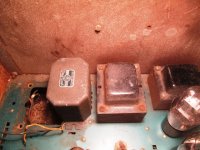
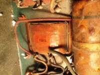
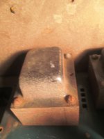
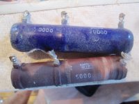
Here are the swinging chokes.
They are incredibly small, and as I found amazing quality too.
I compared them directly with some others I had.
UTC S27 normal filter choke 25H 75m/a RDC = 350.
UTC S30 swinging choke.
As you can see they are similar external size/weight to the T512 animal from Bogen which handles 1/4 amp at 800V.
As for red glowing plates:-
6vheater,
As to red plates:
I had another amplifier that red-plated a 6650 (I turned it off, and fixed the problem before proceeding).
I also had some bad EL34 tubes that had faintly glowing plates. I put in better EL34s.
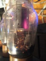
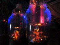
I repeat, the 807 is legendary, but the production spread is huge.
There were various anode constructions and materials (the grey ones seem to be crap), the dark metal ones seem fine,but tend to glow red in 1 corner.
I have loads, and those are exceptionally rare amps which took me years to find.
When they are finished upgrading, they will knock out 175W clean and perfectly reliably.
The output transformers are some of the largest and heaviest I have ever seen in an amp..
One British bloke, Chambers at Chambonino once made a 500W monster using PPP 807s.
It was awesome.
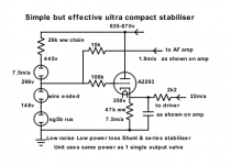
Yes which is precisely why I use a regulator triode to feed the AF amp and driver stage with completely ripple free power.6vheater,
You said noise and ripple of B+ tends to be cancelled in a push pull amp.
That is true.
Starting with several stages of push pull or balanced amplification:
I would caution that if the ripple is present in earlier stages, it can be amplified all the way to the output stages.
The A2293 was made exactly for this purpose, but like any transistor if you short out the output (cathode follower) it will die almost instantly.
Attachments
Last edited:
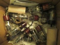
I had to go next door to look at all the stuff and take photos!
I bought a box of 807s off Ebay for about 25USD, and had them shipped.
I think they ended up 1USD each.
I'm sure there's not a single one younger than half a century old.
There were Sylvania, GE, RCA - JAN, all sorts.
I worked my way through all of them at working current and bias (about -28 for 500V) sifting the weak from the strong and UBER strong.
(I do draw the line hot swopping them tho, cos the TC is at 500V and if you try to remove it, you will immediately melt the screen grid - very bright white hot then GOODBYE.)
You can hot swap Octals, (apart from the TT21) but not these...
I have a box here with the remains of them, and a load of half dead 8417s
From the 20 I had, there were 3-4 pairs which matched perfect, you come up 165mV over 4.7rK checker, so about 35m/a - about 18W.
A pair came in at 115mV I reject them,- WEAK.
If they red plate (one blew fuses immediately) or go beyond 210-220mV I reject them. (40-45m/a), cos they will only be a pile of trouble, and unstable.
For those big amps they're going to be fitted with a quad of 5B25x because I start to get nervous with single pairs at over 800V - undocumented settings and all.
I know of only one other person that had an identical pair of those H125s and he had lots of fun with arcing and other stuff, before they behaved themselves again.
On both of mine the power transformers were scrap, with shorts, but who cares they will get changed to 230V anyhow.
I managed to get another 4 of those 50W version, but one was so bad I scrapped it, while on another, practically every transformer and choke was burnt out.
As a result I suppose I know a little about choke input filters and 5R4s/5Y3s.
On one amp the 5Y3 went lit up bright red and died, because it turned out the smoothing choke had a direct intermittent short to ground, smoke came out!
So, in the end I got an identical pair of the "50W" power amps, rebuilt them, swapped the 807s for KT8, (they could scarcely manage a clean 30W when I started work), and that one for guitar a mixer version which is a raging monster, and has its original 60 year old valves.
It's always been suprising to me how cheap the 807 is.
You can still buy them for peanuts, and abuse the daylights out of them.....the 5933 being loads better.....
Sorry about the brief discourse.
It just strikes me, lots of talk about a subject the good old Hiwatt, Bogen, Peerless, heavy metal etc sorted 40-50yrs ago has little point.
Study what they did, you can't go wrong.
Attachments
Last edited:
Whoah, guys...
Seems this thread is getting a bit off topic, discussing power supply and regulator approaches in depth. A lot of stuff to read and to learn, thanks to everyone for the replies!
But let's make the connection back to the original topic: The amp is finished, the PSU design is a FW rectifier into a vacuum diode with a choke input filter in a LCLC structure.
The question is not about changing the amplifier or PSU design, I just need to replace the cooked mains transformer and need the secondary currents to use a transformer with the right specifications this time.
The main points I took home from all your answers:
1. A current sensing resistor at the first choke or at the center tap could do the job. Preferably at the center tap because it would be close to ground potential then.
2. The current waveform will be non-trivial and a cheap DMM will probably not give correct results. A true RMS capable meter would be required.
3. The transformer should be designed for 1.5x the DC load current, or each half of a center tapped secondary 0.75x the load current for a FW rectifier. I would then assume that a center tapped secondary rated for 1.0x the DC load current would be sufficient with my FW rectifier setup.
Any comments to this summary?
If I do not find someone who could lend me a RMS meter, I would choose the long way, measure each DC load separately and then do the sums...
Rundmaus
, one can make the argument that such a choke-input filtering section is almost ideal for solid-state rectification, since a choke blocks all the HF noise that our nearly-magical pieces of purified sand produce.
The simple-as-can-be “solution” of course is to put a modest-valued capacitor up front, before that choke input. GoatGuy ✓
I have choke input feeding a l'amp at 1.6A, with 60K C. The chokes are swinging (though that doesn't matter to my case) and rated at 50mH at 2A. They sing. C is needed up front but there isn't any prior art regarding how much C one can place there, envelope calc or otherwise. I would myself, just haven't gotten around to it yet, too busy to care. The PSU is dead silent at the speakers though, fwiw. I paid $12 for these chokes btw. Surplus.
Last edited:
So far I haven't worked out what valves you are using or how much power the amp is supposed to make. Most transformers are rated in VA with toroids having huge margins of overload.
Go have a look over the border in Poland.
There's 2-3 suppliers who will immediately supply you what and cheap too.
Ogonowski.eu - profesjonalne transformatry do wzmacniaczy lampowych does EI.
Transformatory toroidalne - Producent transformatorow Toroidy.pl Lachovski does toroids.
There's another one also,but I forget the name.
They will advise you better than anyone.
So far I haven't worked out what valves you are using or how much power the amp is supposed to make. Most transformers are rated in VA with toroids having huge margins of overload.
Go have a look over the border in Poland.
There's 2-3 suppliers who will immediately supply you what and cheap too.
Ogonowski.eu - profesjonalne transformatry do wzmacniaczy lampowych does EI.
The transformer i killed was from Ogonowski. Not his fault though, the transformer is capable of delivering according to its spec. I just misjudged the total current draw of the different amp sections.
Had a voltage sag of almost 20V when I compare B+ with the amp in operation and B+ with a load resistor drawing the expected load current...
Rundmaus
Because of the core material toroids have a sharp overload restriction, where the M5 EI-core overloads smoother for the same VA rating. Toroids with lower nominal Tesla rating are less prone to overload sharply. The biggest disadvantage of the EI core (its size and so its price) is its advantage: the more iron the better wrt regulation, cooling and overload conditions. Oh, and there's capacitive coupling from primary to secundary too...toroids having huge margins of overload.
Last edited:
I must know very little then, because I can't think of a mechanism by which a valve rectifier can remove line noise - apart from acting as a resistor. OK, maybe VHF/UHF noise might be attenuated a little by transit time effects because of the anode-cathode spacing, but VHF/UHF noise is unlikely to make it through the transformer anyway.6vheater said:Anyone who knows a little about the subject knows valve rectifiers do a great job of removing line noise - mostly the higher frequency mush which can also come from diodes made of sand.
Gas voltage regulators can add noise.I am a strong believer in removing hum & noise with voltage regulators.
Why try to do with C-L-C filters what you can do so much better with regulator valves or simple gas shunt stabilisers?
Last edited:
I can't think of a mechanism by which a valve rectifier can remove line noise - apart from acting as a resistor.
OK, maybe VHF/UHF noise might be attenuated a little by transit time effects because of the anode-cathode spacing, but VHF/UHF noise is unlikely to make it through the transformer anyway.
Gas voltage regulators can add noise.
There is lots of line noise these days, which tends to propagate all over the place.
Valve rectifiers have a habit of filtering out the mush, because they are quite non linear.... (the full on voltage drop, v the full off voltage drop is quite a big difference compared with a silicon diode with 0.7v), and the output impedance is totally different.
When you combine the effect of cathode follower triode, from a Si diode HT source, you are in effect doing exactly the same thing.
A triode is after all only a diode with an extra electrode.
It can't conduct in reverse, and the output impedance is again the trick.
It's typically of the order of 800-900 ohms, about 2-4x that of a typical smoothing choke.
You have your info wrong about gas discharge regulators.
Zeners are far more noisy, WAY less stable as sources and vary constantly with temperature.
Ask me how I know.
I am not the only person to say so.
Those of us who have experimented with fixed bias systems and direct coupled output stages, found out Zeners were an absolute headache, whereas good "old fashioned" gas discharge worked perfectly, and even produced less heat!
When you use a cathode follower with the gas stabiliser as the reference to the grid, the gain is zero, (0.95) then it goes into a series of resistors with decoupling capacitors et al.
Because you CANNOT connect a discharge tube direct to a capacitor, using as a ref into an amplifier or directly as a high current shunt is the only possible way of doing it.
With CF, (ignoring typical more sophisticated regulators with ripple reduction amplifiers) Any noise created is removed completely down the line by the regulator, which basically ignores all changes in incoming anode voltages, - the rejection ratio related directly to its Mu.
(If you have a constant output current demand, which is normal in an PP AF amp/driver stage, but a strongly changing anode voltage, with OPV load, you will find the output voltage variation from the STAB, is only a very small fraction of the input variation, something easily decoupled.)
I can think of loads of amplifiers this improved out of all recognition.
Last edited:
Gas voltage regulators can add noise.
That noise is quite small.
Using a properly designed gas regulator on output tube screens is generally not a factor to be worried about (one of the most inner layers of the Onion).
Using the same gas regulator on early line stages, or preamp stages can be a factor (it may be one of the dry, inedible layers of the Onion).
Many regulator circuits have significant noise too.
That goes for tube, solid state, and hybrid regulators.
Not all regulators are created equal (stolen from "Animal Farm'; by George Orwell).
"All Generalizations Have Exceptions" . . . That is just one of my generalizations.
Last edited:
Solid state diodes that are used as rectifiers do have stored charge.
Not all solid state rectifiers are created equal (stolen from "Animal Farm'; by George Orwell).
Stored charge can create noise when it is discharged.
Use solid state rectifiers that have less stored charge.
Again, another generalization.
Not all solid state rectifiers are created equal (stolen from "Animal Farm'; by George Orwell).
Stored charge can create noise when it is discharged.
Use solid state rectifiers that have less stored charge.
Again, another generalization.
Gas voltage regulators can add noise.
Mos def. As a bonus, adding a filter capacitor to remove the noise may inadvertently form a relaxation oscillator. (I know DF96 and many others know this, but not everyone does.)
The bigger issue is the current through the tube is limited, limiting utility as a direct shunt regulator. A shunt tube must instead be used to pass higher current, much like a Zener driving a power transistor.
I have some 1960s power supplies using glow tubes and triodes which would benefit from upgrading to Zeners, since I don't need the magical glow.
The reverse-recovery noise of a diode (Qrr) may be eliminated using an RC filter or by using low-Qrr diodes. It's not an insurmountable problem. See, for example, Jim Hagerman's paper:
http://www.hagtech.com/pdf/snubber.pdf
Any of the semiconductor houses will have application notes on reducing Qrr, but likely not as well written.
As far as Zener noise, low-noise Zeners are now available. Vishay is one of a number of vendors.
http://www.hagtech.com/pdf/snubber.pdf
Any of the semiconductor houses will have application notes on reducing Qrr, but likely not as well written.
As far as Zener noise, low-noise Zeners are now available. Vishay is one of a number of vendors.
The bigger issue is the current through the tube is limited*, limiting utility as a direct shunt regulator. A shunt tube must instead be used to pass higher current, much like a Zener driving a power transistor.
I have some 1960s power supplies using glow tubes and triodes which would benefit from upgrading to Zeners, since I don't need the magical glow.
Last one on this.
Usually those that advocate zeners in places to replace GS devices have never tried it.
GS as shunts are a non issue on current ability*, unless used to derive a screen grid current. (eg, CV395) .
If you bias the GS to their max 45m/a at amp start up, as the valves warm up and quiescent comes up, it will dial back all the way to 5m/a before they go out.
That's an 8:1 window with a 1V regulation, 2 in series, it's the same.
I can't get close to that with a zener at 300V.
The GS device is large so runs cool as a cookie.
So, ideally a GS shunt design needs to be running in the middle of the "window".
That gives you 40m/a - (12W) to play with.
Over that range the output is quite linear, erring in the right area, no matter what temp. (they dissipate 6.75W at max to under 1W at min)..
If you try to imitate it with a 10W zener, the huge heat in a much more compact device, makes the voltage output violently unstable.
ie. Derived a bias voltage by putting 40V of 10W 5v-8v zeners in series with the transformer CT**, (instead of the original R-C divider network) only to find it wandered all over the place.....and boy do they get hot!
In effect it was the ground return for the whole amp, shunted by a 4700uF 50V cap.
As the device heated up, the junction voltage floats up and up & which can reach thermal runaway.
That's why large voltage zeners used in old TVs were used with very low currents, and kept away from sources of heat.
Don't worry I have done all this, repeating the experience of Gillespie who made his own solution (EFB), and shared the same sad tale.
Valves with aligned screens (eg 807), have no problem with a direct GS shunt reg, because the screen current is low, and only one of the screen is drawing on a PP amp, so the likelyhood of the stabiliser "dropping out" is low.
You can't use shunt regs on the screens of typical hi gain pentodes, because they have giant screen grid demands.
I've been there done that,- didn't know a PPP pentode pair (18W Pa) could drag easily 50-60m/a into the screen (yes 12-18W on peaks), but now I know!
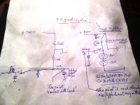
Here are the odd ball shunt & series reg I did.
The "simple" series triode can have the anode voltage waggle around 40-80V or more with zero effect at the cathode, but it has a steady load.
The shunt part of the GS on that only supplies a minute current as a shunt stab, because they only have 1:2 ratio window min to max.
The first one,-
One of the interesting things being old designs used whopping shunt resistors to load up the swinging choke, as well as the C-L-C smoothing choke too.
(That stabilised a resistor divider bias supply in the CT return.**)
I don't see people implementing the shunt R vital idea at all.
I did see a very marked improvement in AF amp & driver linearity using a stabiliser, making it possible to use a lot less NFB.
Attachments
Last edited:
- Status
- This old topic is closed. If you want to reopen this topic, contact a moderator using the "Report Post" button.
- Home
- Amplifiers
- Tubes / Valves
- Current measurement in choke input supply