As a random aside, I started my quest to learn to build tube amps when I was 16 and ordered a schematic for the 3500 from a business in the back of a magazine. I already owned mc30s because I was retro cool before there was such a thing. I went to all the hams and electronic repair shops I could find trying to get someone to build it for me and nobody would. So, I set out to learn to do it myself. From the point of learning to read the schematic I was toting around.
That was many many years ago. To this day, I would not attempt to build one from scratch. At first my dream was crushed by the complexity of the opts and later it was replaced by the realization that high efficiency speakers + amps I could build with off the shelf or common salvaged transformers would work just as well to ruin my hearing.
So, I say go for it, build one from scratch or at least learn what it takes. The quest for knowledge has kept me busy for decades.
I briefly tinkered with Circlotrons about a dozen or so years ago. At the low ratios needed and lack of DC through the OPT, mains toroids work well here for OPT's.
The twin coupled design was published in a magazine at least twice in my memory. Once early in my childhood it was in one of the Electronics magazines of the day, Probably Popular Electronics, or Radio Electronics. In more recently it was in one of the issues of Glass Audio. That's when I tried to make one.....note that I said tried.
One of the features of the McIntosh design was the unique method of feeding the output tube screen grids. They are tied to the plate of the opposing tube. This is also the case with the twin coupled design.
So when a tube is trying it's hardest to pull the plate down to cathode potential, it's screen grid is being driven more and more positive, passing the plate's voltage. This absolutely kills crossover distortion at low volumes, and improves overall linearity, but makes life miserable for the screen grid at full crank.
So take a 6L6GA and ask only 30 or 40 watts from a pair and their high voltage screen grids won't complain......stick in a couple of TV sweep tubes, then plug in an electric guitar, set the controls for the heart of the sun, and hammer away....poof. dead sweep tube. It's used to lining peacefully with 150 volts or so on it's screen grid, so it just fries.
I test every amp I make with a guitar preamp.....if I don't, someone else will. If it don't pass, I don't build it until it will.
A friend and I used to take stuff apart and trace it.....I started out with much lower goals at somewhere around age 12 or so. It was a hand traced schematic of a Fender Champ. I did make one...then another one.....
Today information is much easier to find. Another member here, Pete Millett, the designer of the amp I hot-rodded to 125 WPC has a web site full of tube amp stuff including scans of old books, and yes, McIntosh stuff.
Pete Millett's DIY Audio pages
The MC3500 Schematic is here:
http://www.tubebooks.org/file_downloads/McIntosh/mc3500_sm.pdf
I used a GE industrial transformer that had a pair of 240 Volt winding on its primary, and a pair of 120 volt windings on its secondary. Turn it around and feed it with a Variac. Wire a bridge rectifier on each primary (now the secondary) and some big fat 400 volt caps ripped out of old IBM PC power supplies. This gives you a pair of budget 0 - 350 volts or so floating power supplies.....just the ticket for melting some 6080's, 6AS7's or 6336's.use 120/120////120/120 dual bobbin industrial xfmrs directly to get a floating B+
The twin coupled design was published in a magazine at least twice in my memory. Once early in my childhood it was in one of the Electronics magazines of the day, Probably Popular Electronics, or Radio Electronics. In more recently it was in one of the issues of Glass Audio. That's when I tried to make one.....note that I said tried.
.Getting the effective OT primary Z down using high current tubes will reduce the Vac drive requirements for CFB. TV Sweeps for sure
One of the features of the McIntosh design was the unique method of feeding the output tube screen grids. They are tied to the plate of the opposing tube. This is also the case with the twin coupled design.
So when a tube is trying it's hardest to pull the plate down to cathode potential, it's screen grid is being driven more and more positive, passing the plate's voltage. This absolutely kills crossover distortion at low volumes, and improves overall linearity, but makes life miserable for the screen grid at full crank.
So take a 6L6GA and ask only 30 or 40 watts from a pair and their high voltage screen grids won't complain......stick in a couple of TV sweep tubes, then plug in an electric guitar, set the controls for the heart of the sun, and hammer away....poof. dead sweep tube. It's used to lining peacefully with 150 volts or so on it's screen grid, so it just fries.
I test every amp I make with a guitar preamp.....if I don't, someone else will. If it don't pass, I don't build it until it will.
I was 16 and ordered a schematic for the 3500 from a business in the back of a magazine.
A friend and I used to take stuff apart and trace it.....I started out with much lower goals at somewhere around age 12 or so. It was a hand traced schematic of a Fender Champ. I did make one...then another one.....
Today information is much easier to find. Another member here, Pete Millett, the designer of the amp I hot-rodded to 125 WPC has a web site full of tube amp stuff including scans of old books, and yes, McIntosh stuff.
Pete Millett's DIY Audio pages
The MC3500 Schematic is here:
http://www.tubebooks.org/file_downloads/McIntosh/mc3500_sm.pdf
The MC3500 has a separate primary winding to put a constant 180V on the 6LQ6 screen grids (wrt the cathodes)
Using the opposite plates for screen V would give you constant B+ on the screens, too much for TV Sweeps! But likely OK for 6L6 types.
Time for a couple of Mosfet followers to run the screen grids from some voltage divider R networks from the opposite plates to get constant 150V or whatever for the screens.
I never said any of that. I asked those questions. I especially never suggested taking a part a vintage amp. I don't even like the idea of recaps unless it isn't working, I'm only going for mid-fi, not audiophile. What made you think I thought there was only 1 transformer? I have a mc240 in the living room, it has 3 transformers. I'm not in a competition with you. I've been a enthusiast since I was a kid, my dad also ran the AV department of a big university so I got to play around all the big toys as I grew up as well as help record albums and stuff like that. I admit I don't know much about electronics and amplifiers but I've been into this stuff and making electronics for a good 25-30 years and was a science major at a major university.@ mc240: In #32 you're showing quite some profund lack of knowledge to us: <snip>
Again, I'm not here to compete with anyone, just on a learning path, but that doesn't make me stupid either. Did you guys catch the "secret" windings in the video? McIntosh's own engineering document is 1/4 visible in the video where you can see some of the technical info for the MC275 remake they put out at that time. It's at 2:21 in the video. Does anyone have these full documents?
Nobody has answered if it's legal to make and sell a mac clone using their transformer designs?
Can someone confirm that the people who think they know how to wind a mac transformer see it as a trade secret that they don't want others to know? They want to be paid to do work or just keep it a secret? Is that the kind of situation around these magical transformers?
In a video I found today, Gow says that they have moved on from the original patents and keep improving on them, so they likely have patents on derrivatives of the original unity couples transformes in the early amps.
Thanks for all the info from everyone, it's appreciated.
no, never listened to the mc3500 except at grateful dead concerts when I was a very young kid or baby, so I don't remember... I remember my dad telling me that the greatful dead used macintosh amps, however... I've only listened to a MC240 and other solid state amps.Unveiling the "Mystique" <snip>
Sounds fun, like I said I pop in and out of the audio hobbie, I'm kind of challenged by the weird silence and responses I get everytime I asked about a mcintosh... nobody has quite said that it's too complex for 99.999% of people to build from scratch, but they hint at it. So very weird
I'm trying to figure out the facts still. I like a challenge but I'll probably lose interest again soon. I also think it would be interesting to improve on tape technology... I was reading today about the ips for tape speeds and that tape is still the best quality for high end sound recording and playback. But very little has been done to improve it over the past 30 years... someone should keep developing analog technology, not just keep recycling the same tech from the 1940s.As a random aside, I started my quest to learn to build tube amps when I was 16 and ordered a schematic for the 3500 from a business in the back of a magazine. <snip>
> if it's legal to make and sell a mac clone using their transformer designs?
If you can build a Mac, as GOOD as a Mac, Mac will probably give you a job.
It's not magic transformers, or magic wire, or magic tar. It is a high-wire act of spending "enough" to make a very-very-very-good amplifier without out-pricing all the buyers.
Cosmetics matter a LOT in this price point. The first Mac was not pretty. The later ones with the glass fronts and wonderful metalwork are physically beautiful even when broken inside. Nobody else does work at that level (a few come close in different ways).
Go ahead and build your own Mac. Go ahead and try to sell Mac clones (only do NOT say the word McIntosh or the logo). By the time you have enough GOOD product to go to market, you'll have spent near as much time and money as McIntosh.
Also remember: Bentley built a lot of cars before his 8 Litre, which was SO good that Rolls Royce bought Bentley (probably) to keep the 8L from eating RR's sales. May this happen to you. (Well, without the going-broke part, or the purgatory of working in RR....)
I don't want a job, lol. I could get a job anywhere I want already, but at some point in your life at least for some people you become unemployable because you know more than the boss. But I don't want "a job."
So far, nobody has answered the question of how to make a mac transformer, some have said they can do it but then got real silent... does anyone other than mac know how to do it?
Does mac own this forum or something, lol.
When I left the audio hobbie, Mac wasn't considered near the best amp... are they now? They were considered entry level audiophile... have things changed or did everyone just go out of business in 2008?
So far it sounds like nobody knows how to do the transformers because they are too difficult for a hobbyist... except the guy in Germany who did his own MC3500 on a rusted out scrap transformer winder, but nobody will confirm these facts... so I keep asking.
And I never said I wanted to make makes for a business I was just wondering why everytime someone said macintosh transformer the entire room got quiet. LOL It's hilarious.
Philips AG9007 is good example how to use TV sweep power tubes for Circlotron based 60W amp ,
https://nzvrshome.files.wordpress.com/2018/12/Philips-AG9007-amp.pdf
https://nzvrshome.files.wordpress.com/2018/12/Philips-AG9007-amp.pdf
Yes, that's why I said it was for the new MC275 not the vintage... I don't really know much about any of this except what I've read, thought maybe knowing those numbers from the sheet might help someone.
I've read that the new 275 doesn't sound as good as the original one... maybe it's the circuit board, maybe it's the c core. Am I on the right track?
This page says that the vintage MC240 has better specs than the new ones... interesting...

Link to page: McIntosh MC240 Review
I've read that the new 275 doesn't sound as good as the original one... maybe it's the circuit board, maybe it's the c core. Am I on the right track?
This page says that the vintage MC240 has better specs than the new ones... interesting...
Link to page: McIntosh MC240 Review
One of the features of the McIntosh design was the unique method of feeding the output tube screen grids. They are tied to the plate of the opposing tube. This is also the case with the twin coupled design.
So when a tube is trying it's hardest to pull the plate down to cathode potential, it's screen grid is being driven more and more positive, passing the plate's voltage. This absolutely kills crossover distortion at low volumes, and improves overall linearity, but makes life miserable for the screen grid at full crank.
So take a 6L6GA and ask only 30 or 40 watts from a pair and their high voltage screen grids won't complain......stick in a couple of TV sweep tubes, then plug in an electric guitar, set the controls for the heart of the sun, and hammer away....poof. dead sweep tube. It's used to lining peacefully with 150 volts or so on it's screen grid, so it just fries.
I test every amp I make with a guitar preamp.....if I don't, someone else will. If it don't pass, I don't build it until it will.
This was my big issue with the Vanderveen UC transformer. McIntosh chose their impedance ratio and load line to accomodate the high screen voltage and resulting high Vg=0 knee, so that they wouldn't drive under the knee. Or on a few models they added another winding to feed the screens at a lower voltage. They certainly stressed the output tube screens but they knew what they were doing to make it manageable.
Putting the screen at full B+ and using a 6.4k:8 (Vanderveen ratio) transformer means that even in the 6L6 family of tubes you will be driving way under the knee and screen currents will be huge if overdriven. Something extra has to be done to use that transformer if survival of overdrive is a requirement.
I hung a voltage divider which fed the gate of a mosfet to act as a simple series dropper for the screen with a low zout. I even experimented with a BJT current limiter to pull the mosfet gate down in the even of really large screen currents. Worked, but it resulted in decreased output at extreme levels of drive that looked like volcano craters on a scope with high-level sine testing. Made sense when I saw it but I'm not sure it would be desireable to everyone.
The series dropper mosfet works great to fix the high screeen voltage problem in the UC output stage. I think it actually works better than a separate winding, since you are not filling your window with unnecessary wire and you can make a better transformer with thicker wire on the windings you need.
The same solution would work for a Twin-Coupled arrangement.
This page says that the vintage MC240 has better specs than the new ones... interesting...
Going from a toroid core or C core with two bobbins to an E-I core will sacrifice some HF performance. More winding interleaves only goes so far, until distributed capacitance starts getting excessive.
For low leakage L -AND- low distributed capacitance, the windings must be long and thin and in-phase magnetically for the full length. Toroid does that naturally.
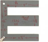
A long E (E-I) can also produce that effect. Partridge OTs used this (it was the BIG secret back then). Long E lams rarely (never) get used these days, but would work perfectly for placing two bobbins on them for the Twin Coupled design (all windings driven by each tube, so in-phase). Long E lams would further increase the performance of a Circlotron also.
I have a 60 lb box of long E lams from Tempel Steel that are M-6 material and made for constant V xfmrs (by adding some shunt shims half way along the long tongue). Two standard bobbins fit on them. They were giving the stuff away as samples 10 years ago, no one making constant V xfmrs anymore.
It is inexplicable that modern high performance (and moderate cost) OTs don't use these type of lams. Just as easy to wind as standard E-I xfmrs. Edcor could easily make high performance OTs with the winding equipment they already have.
(NOTE: for long E's: putting half of a center tapped P-P winding on each bobbin loses the long in-phase advantage, each half of the P-P CT'd winding must extend across BOTH bobbins to get low leakage L and low dist. cap. )
Attachments
Last edited:

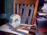
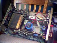
Above pics:
The really Big Long E lam in the second picture I got from a scrap yard in Stamford Ct years ago. A pile of them were in a cardboard box with a shipping label addressed to Dick Sequerra, designer of the Marantz 10B.
The last picture is of a Lambda (or Kepco) power supply. They used long E laminations to squeeze a big power transformer into a lower profile case.
Correction: It apparently was Acrosound (not Partridge) that used the long E lams for OTs.
Last edited:
I doubt CJ lets the specs of there transformers be public knowledge. You really like doing things in the most difficult way possible. For the cost of having custom transformers wound you could pick up an older model and just freshen it up. Also look at Audio Research, probably the best commercially available audio gear made. Now I'm sure I'll get arguments on that but they are top notch gear. I've seen VT100 amps in the 1500 range, 100 watts of power.
I have both a VT100 and a set of Mac MC40 monoblocks and love them both.
BillWojo
I have both a VT100 and a set of Mac MC40 monoblocks and love them both.
BillWojo
JMO, instead of trying for difficult, if not "impossible", projects pick something that's both very good and feasible.I've asked about doing a MC240 clone and it seems like the transformers are too hard to DIY...
So, is it possible to do a CJ clone? How do their designs differ from the MC240?
Are the CJ transformer designs public information?
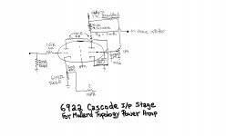
I suggest you use the Harman/Kardon Citation V as the model. The Cit. 5 is a superior implementation of "classic" Mullard style topology. Mullard style will yield decent results, even with O/P transformers of so/so quality. High quality "iron" yields excellent results. Let your budget decide, while still getting good sound.
Supplies of the 12BY7 voltage amplifier are becoming more and more problematic. I've provided a cascode of the in production 6922 as an alternative voltage amplifier.
Attachments
The Unity Coupling or Twin Coupling designs don't stress the screens any more than any pentode design, 'cause they maintain pentode operation during the whole signal swing.
Best regards!
Umm, in "any" pentode design you have the option of setting the screen voltage to whatever you want. In the McIntosh and Crowhurst Twin Coupled designs, you are stuck with Vscr=B+. This is a higher screen voltage than most pentode designs. Thus, you need a lower primary impedance on your OT to hit the knee of the curves, since the knee is up high due to the high screen voltage.
If you use "normal" impedances like 5k or so you will hit below the knee (since the knee is high due to the high screen voltage) and cause very large screen currents to flow on overload and likely melt the screen if you sustain overload. Forget about using a sweep tube in that configuration, the screen is too sensitive. You'd probably melt the screen at idle.
You'd probably melt the screen at idle.
I have experimented with overvoltage to the screens of TV sweep tubes in triode, mostly in SE amps. Even if the screen is not glowing, and the idle dissipation remains at or slightly below max spec, the tubes will eventually go into a runaway condition and something will blow up.
I went through 4 6LW6 sweep tubes in a triode wired SE amp. I started at 400 volts B+ and one channel lost its tube after a few months. I figured, bad tube, replaced it, and the other channel died a few months later. I reduced the B+ into the 330 volt range and lost two more tubes over a year. All went into red plate runaway when left alone at idle. They popped the fuse with no other damage, but the tubes were no good after that. Runaway ensued shortly after power up.
I have also lost two 6W6 tubes which are specified for triode operation in TV vertical sweep operation with 300 volts on plate and screen and 7.5 watts of dissipation. Both were operating on a 320 volt supply in cathode bias, which puts about 275 volts across the tube. Bias was around 30 mA which is a little over the dissipation spec. Both died a runaway death. One lived a long time, the other maybe a month.
The sweep tube in a TV set NEVER idles. It runs at full output all the time. I surmise that they don't like doing nothing, get bored and blow up!
- Status
- This old topic is closed. If you want to reopen this topic, contact a moderator using the "Report Post" button.
- Home
- Amplifiers
- Tubes / Valves
- DIY McIntosh Amp