hi!
I think it´s time to start my own thread about a SRS461 project.
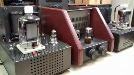
Inspired by the thread by TonyTecson ,and some SRS461 tubes that fell into my hands, I decided to build a push-pull monoblock.That was the point where it started to get out of hand... into a material battle...
The SRS461 tube is the GDR (East Germany) version of the e.g. Philips QE08/200, the quality seems to be near or equal.
- My driver stage works with russian 6SN7-GT tubes.
- The +250V G2 voltage is stabilized by a 6L6-GB.
- All the transformers are custom made by my local dealer.
There are toroidal transformers in the power supply.
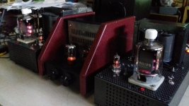
- I use four DCG4/1000 mercury rectifier tubes for a nice optic.
- The output transformer is a PM135 type.
- Everything is mounted on a wooden breadboard and it works fine (all physics to spite)!
- Negative G1 voltage works best at -36 to -37V.
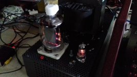
With lower G1 voltages, sinus test signals are distorted, and the SRS461s took too much current and start to glow dark red.
- Anode current is 0,2A idle, with G2 at 250V.
- The unclipped sinus output power is ~200Watts at 8Ohms, for permanent duration. Music power is ~250W.
A video about construction: YouTube
And an actual video with the amp under load: YouTube
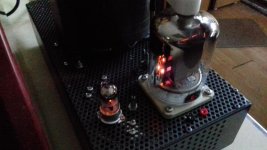
Pics about construction, development, testing... and glowing tubes
DCG4-1000 Quecksilberdampfgleichrichter Rohren | Flickr
Rohrenverstarker Monoblock / QE08/200 - SRS461 - PP | Flickr
https://flic.kr/s/aHsm5GihMb
The current status is: After three years it is still free wired on the breadboard Not only cause I was too lazy, but just because it works so well! And it has done a run about ~300h - without failures due to the wooden breadboard! ...despite of all doctrines.
The few malfunctions that appeared within these 300h:
After 150 - 200 operating hours, there was suddenly a fatal breakdown of the circuit. By analyzing the aftermath, the -36V G1 Bias voltage failed for one SRS461. The Bias voltage for the second tube remained ok.
Unfortunately the anode heat was too much, the glass cracked on the top cap connection. Caused by a shorted grid, the negative G1 voltage then went more and more positive, and the tube blew up. By inspecting the inner systems of the tube, it can be seen that some metal sheet connections were botched in the assembly.
A "military grade" trim pot from surplus started to noise annoyingly in the driver stage after ~250h . Even though it looks like rugged quality.
Why I did that posting:
Now it´s time to build an enclosure. That´s the current status of the project.
The preparations are progressing, but it´s still more planning then assembling.
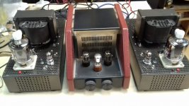
And that´s not all, insanity proceeds: I´ll make a second, identical monoblock for stereo playback.
Some custom transformers are already ordered.
I´ll keep you up to date
I think it´s time to start my own thread about a SRS461 project.
Inspired by the thread by TonyTecson ,and some SRS461 tubes that fell into my hands, I decided to build a push-pull monoblock.That was the point where it started to get out of hand... into a material battle...
The SRS461 tube is the GDR (East Germany) version of the e.g. Philips QE08/200, the quality seems to be near or equal.
- My driver stage works with russian 6SN7-GT tubes.
- The +250V G2 voltage is stabilized by a 6L6-GB.
- All the transformers are custom made by my local dealer.
There are toroidal transformers in the power supply.
- I use four DCG4/1000 mercury rectifier tubes for a nice optic.
- The output transformer is a PM135 type.
- Everything is mounted on a wooden breadboard and it works fine (all physics to spite)!
- Negative G1 voltage works best at -36 to -37V.
With lower G1 voltages, sinus test signals are distorted, and the SRS461s took too much current and start to glow dark red.
- Anode current is 0,2A idle, with G2 at 250V.
- The unclipped sinus output power is ~200Watts at 8Ohms, for permanent duration. Music power is ~250W.
A video about construction: YouTube
And an actual video with the amp under load: YouTube
Pics about construction, development, testing... and glowing tubes
DCG4-1000 Quecksilberdampfgleichrichter Rohren | Flickr
Rohrenverstarker Monoblock / QE08/200 - SRS461 - PP | Flickr
https://flic.kr/s/aHsm5GihMb
The current status is: After three years it is still free wired on the breadboard
Not only cause I was too lazy, but just because it works so well! And it has done a run about ~300h - without failures due to the wooden breadboard! ...despite of all doctrines.The few malfunctions that appeared within these 300h:
After 150 - 200 operating hours, there was suddenly a fatal breakdown of the circuit. By analyzing the aftermath, the -36V G1 Bias voltage failed for one SRS461. The Bias voltage for the second tube remained ok.
Unfortunately the anode heat was too much, the glass cracked on the top cap connection. Caused by a shorted grid, the negative G1 voltage then went more and more positive, and the tube blew up. By inspecting the inner systems of the tube, it can be seen that some metal sheet connections were botched in the assembly.
A "military grade" trim pot from surplus started to noise annoyingly in the driver stage after ~250h . Even though it looks like rugged quality.
Why I did that posting:
Now it´s time to build an enclosure. That´s the current status of the project.
The preparations are progressing, but it´s still more planning then assembling.
And that´s not all, insanity proceeds: I´ll make a second, identical monoblock for stereo playback.
Some custom transformers are already ordered.
I´ll keep you up to date
Tobi461,
that was very impressive, i envy you that you were able to start something, i am still dreaming of the day when i can complete this amp.....of course my excuse is the persistent lack of funds...add to the fact that i am also lazy.....
in my build, this is what i plan on doing:
1. monoblock construction, a chassis for each channel...i dislike umbilical chords...
2. regulated G2 and G1 bias supplies....mosfet aided regulators..
3. mosfet source followers to drive G1 grids directly so that AB2 is possible..
4. a mullard 5-20 like front end..
5, the front end power supply is autonomous with that of the output stage....
6. etc, as i build it....maybe a no global feedback build, but i will have a facility to do that if need be.......
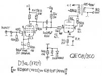
My monoblocs with QQE08/200 and D3a:
Attachments
Good work. I'd include a protection circuit like the one used on one of Patrick Turners amps, see attached (Q5 etc). I put one on my 120w EL34 amp and it has been very useful especially when mucking about making changes. Not shown is a 15r "sense" resistor between cathode and ground of the OP valves, I used 10r in mine and tweaked R8 and R10
Hope you make a start Tony, once you get cracking the bug should get you and provide impetus.
Nice fettling davourin : ).
Andy.
Hope you make a start Tony, once you get cracking the bug should get you and provide impetus.
Nice fettling davourin : ).
Andy.
Attachments
Last edited:
QE08 / 200 is connected as triode (G2 to A), and output power is P ~ 20W in class A1 without current G1.
The cathode current is Ik ~ 170-180mA, and the amplifier works very stable for 3 years.
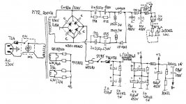
Attached to the amplifier and rectifier scheme:
The cathode current is Ik ~ 170-180mA, and the amplifier works very stable for 3 years.
Attached to the amplifier and rectifier scheme:
Attachments
PM135 is/was a standard for laminations in Europe, or in Germany at least. Winding windows' size and center part mate with the better known M102 standard, but the yokes are wider, and there are two cuts from the center to the outside. Hence the yokes are interrupted twice.
PM is acronymous for Philberth-Mantel, the standard was introduced in about 1965. A power transformer with a 54 mm high PM135b core of M6X (VM111/35) GOSS laminations has a rating of 350 VA, compared to 180 to 200 VA of a M102B one with normal electric steel lams.
I think that PM laminations have all but vanished nowadays. Even Waasner, Germany, the (to me) last known manufacturer for PM's, doesn't offer them any more.
Best regards!
Last edited:
Thanks for all your replies, I will answer them after some new pics!
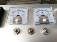
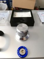
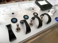
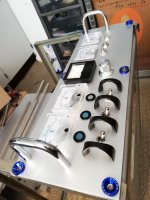
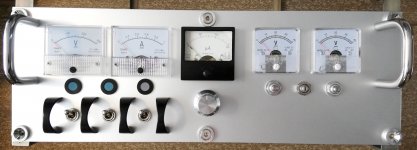
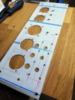
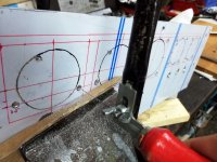
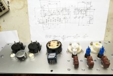
This is how the front plate will look like. The signs are still missing.
During operation it has become clear that monitoring of the following values is important: total current consumtion (1A gauge), G2 250V (300VDC gauge), negative G1 voltages (40VDC gauge). Output power is nice to have (300uA gauge).
In an earlier design I desired to have a fully automated design with time relays which start after a specific time for the rectifier tubes and some more.
At a closer look, that will bring more sources of error.
An automated process is not necessary, the operator should know what he´s doing.
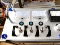
Now I use three power switches for three stages of operation:
1. pre-heating DCG4/1000
2. auxiliary voltages and heating of preamp and SRS461
3. high voltage
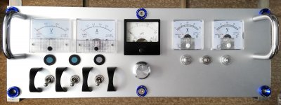
The blue highlights took up the topic of the blue glowing rectifier tubes.
The second monoblock will have silver washers on the front plate
This is how the front plate will look like. The signs are still missing.
During operation it has become clear that monitoring of the following values is important: total current consumtion (1A gauge), G2 250V (300VDC gauge), negative G1 voltages (40VDC gauge). Output power is nice to have (300uA gauge).
In an earlier design I desired to have a fully automated design with time relays which start after a specific time for the rectifier tubes and some more.
At a closer look, that will bring more sources of error.
An automated process is not necessary, the operator should know what he´s doing.
Now I use three power switches for three stages of operation:
1. pre-heating DCG4/1000
2. auxiliary voltages and heating of preamp and SRS461
3. high voltage
The blue highlights took up the topic of the blue glowing rectifier tubes.
The second monoblock will have silver washers on the front plate
Attachments
-
 SRS461-Frontplatte-9.jpg378.7 KB · Views: 154
 -
 SRS461-Frontplatte-8.jpg270.8 KB · Views: 121
 -
 SRS461-Frontplatte-7.jpg414.6 KB · Views: 126
 -
 SRS461-Frontplatte-6.jpg338.2 KB · Views: 154
 -
 SRS461-Frontplatte-5.jpg409.7 KB · Views: 376
 -
 SRS461-Frontplatte-4.jpg234.2 KB · Views: 399
 -
 SRS461-Frontplatte-3.jpg247.7 KB · Views: 362
 -
 SRS461-Frontplatte-2.jpg578.4 KB · Views: 375
 -
 SRS461-Frontplatte-1.jpg490.8 KB · Views: 368
 -
 SRS461-Frontplatte-10.jpg353.9 KB · Views: 155
Hi Tobias,
very good job....how is the tube supply in your place?, how much do these tubes cost where you are located?.....i got my quads for less than U$120 simply because no one else wanted them...
- Status
- This old topic is closed. If you want to reopen this topic, contact a moderator using the "Report Post" button.
- Home
- Amplifiers
- Tubes / Valves
- SRS461 | QE08/200 Monoblock Amps