Also output voltage is measured for each input signal level (Good old Sangamo AC meters)
Output voltage for the scope screenshots above are:
2.2 Vrms, 2.75Vrms and 3.3Vrms respectively (0.6W, 0.9W and 1.3W)
No idea WRT the level and distribution of THD, is there a way to make an educated guess by visually looking for the onset of 'rounding' of the sine wave peak?
Output voltage for the scope screenshots above are:
2.2 Vrms, 2.75Vrms and 3.3Vrms respectively (0.6W, 0.9W and 1.3W)
No idea WRT the level and distribution of THD, is there a way to make an educated guess by visually looking for the onset of 'rounding' of the sine wave peak?
Last edited:
I have been enjoying your thread, and am planning one of these little amps myself when I get another project behind me.
My front end tube will be 6S75 ( because I have some ), if I did the conversion to English right, and I am thinking of a MOSFET split load with push pull 6P30, so I can use some cheap 70 volt line transformers that I have.
Win W5JAG
My front end tube will be 6S75 ( because I have some ), if I did the conversion to English right, and I am thinking of a MOSFET split load with push pull 6P30, so I can use some cheap 70 volt line transformers that I have.
Win W5JAG
W5jag,
Thanks for the compliment! I'm not fond of my writing style here, I usually come across muddled and hand waving. I do much better when I give the report writing the time it needs.
This small amplifier I will eventually put to use as a small kitchen/bathroom system (water as far away as possible!) Or I other words a Musak/elevator music system, so a watt is ample, provided I get some speakers that are slightly more sensitive.
The original input stage using 5744 will be put to use as a mini guitar amplifier, although I haven't decided whether to design as a single ended design. If I crank the input stage far enough and drive the output to >4.5V in the current circuit then I eventually get to cut off clipping. Should be a fun experiment!
Push pull with a pair of 6P30B is the next mission, though I'll bet you'll beat me to it, as I'm already thinking of paralleling a pair of 6P30B n the output stage, just to see what happens!
I recently discovered that the 5744 tube is used in a well regarded tube amplifier microphone which is a modern emulation of the AC701 tubed mics of old so the next adventure may be a mic preamp for my studio setup
Last edited:
So, in my vague hand waving way I'll attempt to assess the performance shown in the scope screenshots posted Above:
At 0.6W output the outputlooks fairly good, not too assymetrical, slight rounding at the bottom of the waveform (inverted trace so that's the positive going part of the cycle)
At 0.9W things begin to worsen, with the increase in rounding as signal input approaching 0 grid volts. I believe that it is still at least listenable at this point
At 1.3W things are starting to get wonky. I don't think I'd be listening to that without noticing the increase in crud!
Just when I'm about to get ballshy, life humbles me again 
Hi, So back on Friday I was rather chuffed with my efforts, power output is pretty much there. I posed the question: "Is there a way to judge the level of distortion by the rounding off of the sine wave peak?" Well I think today I answered the question myself. I've never been able to figure out how to use the FFT function on the decent DSO I use at work - I have a reasonable CRO at home, of course no FFT function. So today at lunch I set up the DSO and refreshed my maths and went to work trying to get the scope to show fundamental through to 5th harmonic. More to come on that once I take some more results. .. The answer was: "If I did the maths right, about 10% at 1.3W" Humpf.... So I'm not going to post the updated schematic with voltages that I drew up over the weekend.... But it's positive right? Of course it is. So I went about re-biasing the triode stages, starting with the input stage. This stage was biased at about -3.33 V with a series parallel string of 4 red (2mA) LEDs, which gives a Va just over half B+. Remembering the 2/3rds rule of thumb, I removed the LED string, and replaced with cathode R and an arbitrarily large 1000uF bypass C. Some improvement....
Hi, So back on Friday I was rather chuffed with my efforts, power output is pretty much there. I posed the question: "Is there a way to judge the level of distortion by the rounding off of the sine wave peak?" Well I think today I answered the question myself. I've never been able to figure out how to use the FFT function on the decent DSO I use at work - I have a reasonable CRO at home, of course no FFT function. So today at lunch I set up the DSO and refreshed my maths and went to work trying to get the scope to show fundamental through to 5th harmonic. More to come on that once I take some more results. .. The answer was: "If I did the maths right, about 10% at 1.3W" Humpf.... So I'm not going to post the updated schematic with voltages that I drew up over the weekend.... But it's positive right? Of course it is. So I went about re-biasing the triode stages, starting with the input stage. This stage was biased at about -3.33 V with a series parallel string of 4 red (2mA) LEDs, which gives a Va just over half B+. Remembering the 2/3rds rule of thumb, I removed the LED string, and replaced with cathode R and an arbitrarily large 1000uF bypass C. Some improvement....
Last edited:
I had no qualms about GNFB
Had being the operative word
Or really, my ability to just "get GNFB" to work right away haha!
So I quickly tried to implement a frankly awful attempt at GNFB, splitting the cathode resistor and feeding the output from the OPT plate connection via 100k pot wired as VR and added series resistance. Phase is OK, just a daft attempt that wasn't really thought through.
That route got abandoned pretty quick!
"Do it right before FB" or basically "Don't polish a t**d"
Or words to that effect... It really resonated.
So I just removed the cathode bypass.
Instant marked improvement. OK loss of gain but...still...
No time for noting numbers, lunch over.
Messing with FFTs
So today I dug a little deeper into an attempt to measure THD and optimise my circuit. Starting at the beginning, I set up the DSO to view an inputted Square wave signal, adjusting scaling and sample rates to show 500Hz/div horizontally, using timebase delay to locate the fundamental somewhere convenient. Y-axis set for 10dBm/div initially. Then I took some readings, before plugging them into a spreadsheet calc which performs the Root sum calculation. I logged only the fundamental 1n up to 5n. I get variable results, broadly repeatable, of between 0.3% and 0.7% over 4 iterations of the test. Can anyone lend me some experience? Is the variability I see in my recorded figures due to limitations in the accuracy of FFT functions on a DSO? Or something else? All in all for a grounded cathode gain stage with unbypassed cathode resistor, I was quite pleasantly surprised at the outcome. I'm just not 100% confident in my variable results
So today I dug a little deeper into an attempt to measure THD and optimise my circuit. Starting at the beginning, I set up the DSO to view an inputted Square wave signal, adjusting scaling and sample rates to show 500Hz/div horizontally, using timebase delay to locate the fundamental somewhere convenient. Y-axis set for 10dBm/div initially. Then I took some readings, before plugging them into a spreadsheet calc which performs the Root sum calculation. I logged only the fundamental 1n up to 5n. I get variable results, broadly repeatable, of between 0.3% and 0.7% over 4 iterations of the test. Can anyone lend me some experience? Is the variability I see in my recorded figures due to limitations in the accuracy of FFT functions on a DSO? Or something else? All in all for a grounded cathode gain stage with unbypassed cathode resistor, I was quite pleasantly surprised at the outcome. I'm just not 100% confident in my variable results
Last edited:
After what seems like an age...
I've been real busy lately and haven't had a huge amount of time to experiment in the lab. I've finally got to grips with the awful FFT function on my 'good' DSO.....I googled it an lo and behold..... If you need a laugh or are just curious how torturous the device is the see below: YouTube What time I have had has been spent becoming accustomed the the DSO severe limitations. I have been able to measure THD of my initial circuit at various points, and I have changed the second stage to a cathode follower. Some results to come, just need collating and uploading tomorrow once I've finished work for the week!
I've been real busy lately and haven't had a huge amount of time to experiment in the lab. I've finally got to grips with the awful FFT function on my 'good' DSO.....I googled it an lo and behold..... If you need a laugh or are just curious how torturous the device is the see below: YouTube What time I have had has been spent becoming accustomed the the DSO severe limitations. I have been able to measure THD of my initial circuit at various points, and I have changed the second stage to a cathode follower. Some results to come, just need collating and uploading tomorrow once I've finished work for the week!
As promised...some data!
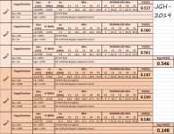
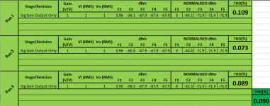
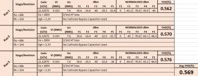
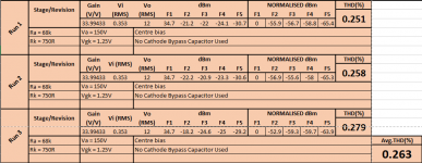
Hi, Well after some much needed lab time I have got some results from my testing, which appear to be a lot better than I had first thought. the attached image "Data1_CONTROL" shows my Signal Generator D.I. into DSO input and the results of the FFT - This was done to find the bottom line for THD measurement using the equipment I have at hand. At broadly 0.1 % in level, the THD from the Sig Gen is now not something I will lose sleep over! The other images show various anode loads and the respective measurements of THD obtained during testing. The results are repeatable, and quite good levels of THD. There is only one configuration which yields best compromise of gain and THD. Frankly, i'm still surprised that I measured less than 0.3 % I hope that it isn't a flaw in my maths or method - for once I'm fairly confident it isn't my maths at fault!
Hi, Well after some much needed lab time I have got some results from my testing, which appear to be a lot better than I had first thought. the attached image "Data1_CONTROL" shows my Signal Generator D.I. into DSO input and the results of the FFT - This was done to find the bottom line for THD measurement using the equipment I have at hand. At broadly 0.1 % in level, the THD from the Sig Gen is now not something I will lose sleep over! The other images show various anode loads and the respective measurements of THD obtained during testing. The results are repeatable, and quite good levels of THD. There is only one configuration which yields best compromise of gain and THD. Frankly, i'm still surprised that I measured less than 0.3 % I hope that it isn't a flaw in my maths or method - for once I'm fairly confident it isn't my maths at fault!
Attachments
Of course the results are only the THD of a single grounded cathode stage, and assuming I need two gain stages before the output stage, then I can expect THD to be higher at the next stage, although I think some cancelling may occur if both stages invert the signal.
Of course the largest contributor to THD in my initial measurements, is the output pentode, which is guess is adding somewhere in the region of 5% THD at max signal level of 1V p-p.
Hopefully though, the effort in minimising the THD in preceding stages will pay off and allow a better end result.
That is, once I've got a better idea on how to use feedback on the output stage, or global feedback to reduce THD further.
Hi,
The OPT were a purchase from a member here in DIYA. They were used and about €30 each. They are Jan Wuesten ATRA0288 (which I believe is a old part number, and I think there is a equivalent replacement). They are rated for DC current of 60mA max. And 5-6Watts. They have both 4k and 5k taps, 4 and 8 Ohm secondaries.
I am misusing them slightly, using the 4k primary and 4Ohm secondary but an 8Ohm test load.
In its current state the pentode stage seems happiest with the reflected load of 8k.
I am a little hesitant to recommend the OPTs (or rather I am hesitant to recommend my implementation of them), they are hefty quality items, and although I haven't measure the frequency response of them in action, I notes that output voltage is probably halved at 40Hz or so. The stage is unloaded to a degree below about 100Hz.
At the end if the day, this is my first valve tube circuit, and it's entirely possible that someone else can find a better implementation of an OPT than I can haha
Long story short I was expecting better performance using the 4k or 5k tap as intended, but it just didn't work out that way and the circuit needed a lot higher transformer impedance.
However that isnt a bad reflection on the OPTs, it may be that something isn't right in my circuit or my calculations, that lead me to choose a 4k/5k OPT.
Last edited:
The story so far...
So after a couple of weeks parsing about...
I was able to measure nice low THD and optimise the input stage (post #30).
This is the THD measure of the circuit in the attached schematic (circuit A, when couple to a follower), I haven't taken measurement of the follower output, but the THD spectra looked much worse than the input stage.
This was a bit o a surprise, since all I know of followers is 100% NFB, high input Z low output Z, so I was expecting a far better result. However I've yet to quantify with measurements, but I was basically expecting the same output more or less, as what I measured inputting the follower (at low THD)
I'm at a bit of loss to explain that, but I accidentally built the follower as a fixed bias type rather than self bias (from Merlins pages/books), so maybe that has something to do with it. I'll revisit the follower again soon.
Using the follower after input triode stage, gave a nice load for the input triode, so despite degenerated cathode, gain is good.
I biased for 1/2 B+, and gain is about 1/2 mu. This is the sweet spot for THD and gain it seems.
Attachments
Motorboating...
So then I returned to the original circuit, more or less, input stage, 2nd gain stage then outputs. All open loop! After a minute pondering the 1Hz flicker of a indicator LED in the screen circuit, I realised my error.
I ran a wire to a 47k potentiometer, from the output of the 2nd stage to the cathode of the 1st stage, and I think I managed to affect some NFB over the 2 stages. THD looks OK. Certainly improved. Some measurements to come when I have the time to upload them all!
Now I have to consider how to proceed.
Input stage (×33)--->CF--->6P30B (no LNFB)
Or
Input stage (×12)--->Gain stage (×3)--->6P30B (plate to cathode NFB)
And which one will get there with less THD... guess I'll find out...after a lot of tests...
Of course, the answer comes while on the throne
As I guess a few people experience this, while contemplating life and all things existential at those mundane moments (while showering, brushing teeth or sitting on the WC, the answer/inspiration strikes.
My input stage measured very good, almost too good THD figures - then it dawns on me....
It is driving the relatively high Z in of a cathode follower, so is only very lightly loaded, as opposed to the case where the 2nd stage is another common cathode gain stage with much lower input impedance. Hence the drop in output of 3 times and increased THD.
That coupled with my little knowledge of cathode followers lead me to expect a better result outputted from the follower, than I realised in practice.
See, being of the op amp generation, I automatically assumed THD would be outstanding using even a simple cathode follower, when in reality it's poor (5% or worse)
So having tried a fixed bias follower, I now also have tried a self bias type, with rheostat in place of To to vary the biasing point.
To my mind, having a 12Vrms signal input to a follower with centre bias at 150V, there should be plenty of headroom to accommodate the signal swing, provided I can get the bias to say -15V Vgk and accomdate the entire signal at the grid.
And I'm not having any luck with that so far....
Maybe I should try splitting the anode load and feeding to the follower. bootstrapping? Is this a mu follower?
Perhaps then I can achieve reasonable gain, THD, AND good drive capacity for the output stage
So...going back to the drawing board....
Or so the saying goes.
It's ever so easy to get lost in tinkering with tubes, no crack and a whirl of magic smoke to alert you to a slightly silly bias or circuit mod.
Despite my somewhat haphazard tinkering, I still haven't destroyed a tube (except one that rolled off the desk, which I'm not counting)
I'm almost slightly disappointed. I usually destroy silicon quite readily
Right now I'm running the output tubes 6P30B in the same circuit, more or less, that I started with (post 5 or so).
Using the pentode in this way (Va=300V, Vg2=250V, Vg1= 41V), I have flitted between using it OL, and using LNFB from plate to grid, to limit gain to around 10-12 times V/V.
In my travels I have measured THD of each stage preceding the output stage, and I seem to have gotten THD to a reasonable level. But the pentode THD itself is still dominant, almost depressingly so.
I figure, with Vg2 at it's max of 250V I'm operating the valve as pretty much as close to triode operation as possible (without actually wiring for triode mode) - so while running as a triode wired pentode would lower the output THD, I believe (I don't know) that the reduction in THD wouldn't be huge, if I were to wire as triode. At least it would be a trade of THD for power output.
An up to date schematic is incoming btw (just my pc died and left me a bit stuck)
So...following that train of thought, why bother to try triode?
I probably will, but that might need to be a new thread, so this thread doesn't end up somewhere completely different from "SEP"
Anyways...
Working backwards from the output stage, knowing at the operating points I'm using I have about 32V peak as a limiting factor (Vgk1=-41V) for full output (I'm generally using 2.85 or 3 Vrms across 8R2 as a target, from initial experiments)
If you study the plate curves for the 6P30B (single anode) pentode then you may have noticed that there is no 0V bias curve. If memory serves it starts at -4V, and taking twice that from the Vg2 voltage leaves about 32 V peak swing for input headroom to the grid
So...call that 13 Vrms for a touch extra drive.
Of course that's open loop....
Following on, I have been thinking that If I can't achieve the voltage gain in a single stage, then perhaps a 2 stage VAS with lower mu devices would work better?
And if I use a 2nd VAS then that stage needs to be biased sufficiently to accodomate the input signal from the preceding stage. That's quite a trick in itself!
So using the 6S6B triode that's what I've tried to do. Initially I increased To until I got to a bias of about -5.5V, and found THD measured better somewhat lower (Vg1 Of-5.5V gives ~200V on the anode, which is far to near cut off. At Vg1 of -4.5 looks a bit better, with Va at 170V (B+ 250V).
Then to maximise gain from a 5V peak I bypassed the cathode resistor with 1000uF.
Every time I do it I hate the increase in THD.
So again it's back to the LEDs (perhaps I didn't give the bypassed Rk enough chance?)
Using a string of 2 Vgk ends up neatly about 3.4V.
I'm not expecting great results after measuring a degenerated cathode circuit open loop, but its not bad....quite good actually. Better than the result I got with bypassed cathode resistor.
The anode quiescent voltage isn't identical in these cases, so perhaps I need to revisit the test with the same Vgk.
Then as I have plenty of gain, I used LNFB plate to grid (again) in the triode, and started building an input stage to drive from up to 1V peak input to drive the 2nd stage.
I've also reduced gain of the pentode by setting plate to grid feedback to give about 6.5 times gain, and I may yet reduce it further, provided I can still drive the output far enough, in terms of OPT output watts.
Schematic and more to come (when I retrieve my notes!!!)
- Status
- This old topic is closed. If you want to reopen this topic, contact a moderator using the "Report Post" button.
- Home
- Amplifiers
- Tubes / Valves
- SEP using 6P30B and 5744WB/6C7B