So today I had a little time to explore a bit more.
Using two triode VAS stages with gains of about 8 and 4.5 V/V, gain limited by plate to grid NFB at each stage, I get pretty good drive, maybe 32V p-p or so, THD at the output of the two stages is good, conservatively under 1%. Tentatively I'd say it measured far better than that. Perhaps a bit of cancellation occurring between these two inverting stages?
I now have drive at 1V p-p (0.353Vrms) input signal, to overdrive the output to gross distortion at some 5V, despite the pentode local NFB.
In a couple of iterations I drop the pentode FB resistor ratio to reduce gain to 2-3 times V/V. At the same time increasing the aim of the first stage to compensate for 2.8Vrms output across 8R2. In the end, after reducing the 2nd stage gain as well, I end up with the medium mu 6S6BV tube running open loop.
Then measuring THD at the node joining the triode stage output to the pentode power stage again, I'm a little disappointed at the result as THD is now 1 - 2%.
No surprise I suppose as I have reduced both input and output impedance across all stages....
Measuring THD of the amplifier output (primary side of OPT) I get variable results but in the order of 5% or worse at max output.
I'm going to try feedback for OPT secondary to 2nd triode stage cathode and see if I can get some distortion cancellation that way, although I do understand that the prime reason for NFB is reducing output impedance and has a minor effect on THD.
So next up, maybe I should try a parallel pair ( a SE||P? )
I've mostly measured the amplifier THD referred to OPT primary, though a cursory glance at the spectra on the secondary side is marked different, dare I say better?
Maybe I should be measuring the secondary output anyway...
That's what the speaker will 'see' afterall
Opinions most definitely welcome.
Last edited:
So today I had a little time to explore a bit more.
Using two triode VAS stages with gains of about 8 and 4.5 V/V, gain limited by plate to grid NFB at each stage, I get pretty good drive, maybe 32V p-p or so, THD at the output of the two stages is good, conservatively under 1%. Tentatively I'd say it measured far better than that. Perhaps a bit of cancellation occurring between these two inverting stages?
I now have drive at 1V p-p (0.353Vrms) input signal, to overdrive the output to gross distortion at some 5V, despite the pentode local NFB.
In a couple of iterations I drop the pentode FB resistor ratio to reduce gain to 2-3 times V/V. At the same time increasing the aim of the first stage to compensate for 2.8Vrms output across 8R2. In the end, after reducing the 2nd stage gain as well, I end up with the medium mu 6S6BV tube running open loop.
Then measuring THD at the node joining the triode stage output to the pentode power stage again, I'm a little disappointed at the result as THD is now 1 - 2%.
No surprise I suppose as I have reduced both input and output impedance across all stages....
Measuring THD of the amplifier output (primary side of OPT)
I've mostly measured the amplifier THD in this way, though a cursory glance at the spectra on the secondary side is marked different, dare I say better?
Maybe I should be measuring the secondary output anyway...
That's what the speaker will 'see' afterall
Opinions most definitely welcome.
As promised...schematic attached
As promised, here is my updated circuit schematic (attached)
So after some time considering things, I opted to wire a pair of output pentodes in parallel and see how much extra power, or lower THD I can achieve.
This is a story itself (but for the next post)!
I have both 6P30B pentodes, and 6P30B-R.
There seems to be a huge amount of misinformation on various tubes online - and merely just finding data for the 'B-R' variant is nigh on impossible (no curves to speak of, just characteristic data tables)
Skipping the story until next post, all I will say is that these pentodes aren't all that similar, at least in terms of their Vg2:Vg1 characteristic. The "B-R" variant has internally connected G3 to cathode, and twin anodes.
As can be seen from my measurements, now at ~1.2W output I get about 1.3% THD
Bloomin' Marvellous!
Attachments
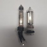
6P30B vs 6P30B-R
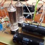
When I bought my Russian pentodes, I bought a few of each variant (6P30B and 6P30B-R).
The former are the usual diameter, similar to most other pencil tubes, however the "-R" variant is much larger diameter.
The plate materials are different, mid grey oxide coated, verses shiny (Nickel?) Electrodes, and no better flashing in the "-R" variant. The electrodes are significantly larger too, probably a factor of 2 or more.
In my personal opinion, I don't really like these bright nickel getterless tubes. No rationale behind it, other than my guess that heat dissipation isn't as good, and a gassy tube stays gassy.
Other large differences are the relationship between screen volts and grid bias volts.
With 6P30B I can bias at -42V using Rk=2k (screen at 250V)
With 6P30B-R I only get to -33V using Rk=2k (screen at 225V), under identical screen volts, the bias is still maybe -35V.
For these reasons I prefer the slim 6P30B, but seeing as I haven't got another pair, for the moment the testing with paralleled output pentodes has been limited to the "-R" variant.
Some needed modifications to the schematic:
2 independent zener regulator circuits, one for each screen supply. (Right now I'm using a single supply to both screens)
Grid shoppers of 1k2 not shown but in use.
Trim cathode resistance on both pentodes to get the same bias volts. (At the moments, one pentode grid sits at 31V and the other 33V)
Perhaps I should also add anode stoppers/current sharing resistances?
Deep thought reqd
Happy holidays!
Attachments
Last edited:
Easter experiments
Hi.
So I had a couple of extra days off this Easter, and got around to trying to tweak the circuit I have (last post) for better THD at max input signal level.
First off I removed the LED bias and reverted to 750R || 1000uF, and used Rp of 33k which gives a Vgk of 3.4V (the same as 2 x 2mA LED string) cathode current of about 4.5mA (11 or 12mA is max idle, so I could bias hotter)
Previously I had achieved good results with a lower Rp when using unbypassed cathode resistance, but the loss of gain is probably half or more.
But it was a far warmer bias, Rp 12k or 15k..do I really need to bias hotter?
Quick eyeballing of THD, is maybe 4-6dB higher across the board. Vak is slightly lower, maybe 5 or 8 Volts. Overall gain appears slightly lower but could be measurement error.
So I revert to a single LED for a bias of 1.7V which gave similar, maybe fractionally worse results.
So perhaps the LEDs stay on the input stage...
Maybe next the 2nd stage should revised and biased hotter instead.
That being said, the trend I'm seeing is 0.5% THD at the 1st stage output, 1% at the output of the 2nd stage. Interestingly, measured at the secondary of the OPT the THD is about 1% too....
Matching tubes at by their Vgk1 Voltage at idle.
Well.
Since I found that the parallel pair of 6P30B tubes weren't biased at the same volts on the control grid, I switched tubes until I got a pair which had very similar Vgk readings (32.5 and 32.9 Volts vs the previous 30.5 and 33 Volts)
Screen 2 Volts are zener regulated and read identical voltages.
Now my instinct was that perhaps THD would improve, but another quick eyeball showed it was perhaps 3dB worse over odd harmonics. Oddly 2nd harmonics some 10dB lower than 3rd....
I'll have to check again when I get some more time....
I wonder.... Has anyone deliberately used a spread of paralleled tubes, with widely varying grid bias volts? And to better effect thrn when matching DC conditions.
Matching for gain is probably the best idea, I imagine
Last edited:
Some random maths
I'm not one for mathematical contemplation but the following thing has occurred to me (assuming the math is correct)
From:
Pa = (Vgk/Rgk)(Vak- Vgk)
For the unbalanced case rearranging
ra = (Vak- Vgk)(Vgk/Rgk)
ra1 = (300-33)(33/2000) = 16181 Ohms
ra2 = (300-30.5)(30.5/2000) = 17672 Ohms
About 1k5 difference.
Perhaps adding a (wasteful) anode resistor to each tube, maybe 200R or so, would help...
Perhaps I'll try that, though it would require a rethink to layout as it stands without awkward PCB/stripboard acrobatics
Forgetting about current sharing resistors for the moment
Today I had 30 mins to tweak the circuit some more.
Calculating Pa for each pentode from the most recent data from earlier:
Pa1= (30.5/2000)(300-30.5) = 15.25mA * 269.5 = 4.1W
Pa2= (33/2000)(300-33) = 16.5mA * 266 = 4.4W
Which gives a Pa of 75-80% of Pdmax.
Previously I had found when using a single output pentode, that I got best results on the scope at idle current of 19-20mA, which gave a Pa of more like 5W, close to the limit of Pdmax.
So I reduced the 2k cathode resistor to 1k8 using a 18k parallel resistor. (This while using the pair of tubes that 'matched' on bias point values)
This gives idle current of 35/1800 = ~19.5mA and Pa of about 5.1W (slightly lower as PSU sag means B+ is slightly lower now, maybe 295V)
Now, using the current gain structure, I can squeeze more like 2.5W output at similar THD (about 1.25%), and half or less that level at 1W.
In a wild moment I changed the OPT tap (from 4k to 5k, while still using 8R load on 4R WDG).
THD dropped maybe 0.25%, 2nd harmonic in particular is reduced IIRC.
But...
In order to get to 2.5W output, I drive 3V p-p (1V rms) into the input. The designed max input was intended to be between 1 and 2V p-p (0.353 to 0.707V rms), to accomodate lower level devices such as mp3 players as well as normal domestic line level outputs.
Now I have a shortage of gain...over zealous application of LNFB!!!
Next on the plan then, is to tweak the gain structure of the 2nd triode stage and perhaps pentode stage (although the results are fairly good, so at this point, I am not sure any improvements will be found.)
Either way, I will reduce the LNFB one stage at a time, to increase gain in order to realise the 2.5W output at 2V p-p (or as close as I can get to that), and monitor the 'penalty' in THD...
Next time...
Last edited:
Small Changes
In the quest to realise reasonable output watts, at reasonable THD, I have made some small changes to the gains of the 2nd triode stage and the pentode stage also.
Also I made a small change to the pentode screen supply, reducing the series resistor to 10k as I believed that the screen was drawing a very low current, even at maximum output.
Currently I measure a max of 1mA screen current, and screen voltage has zero or very little sag at max output; reducing the resistance has increased screen current very slightly.
As it doesn't seem to be doing a lot I may return to the original value, of 24k.
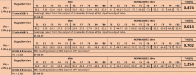
Gains are now as follows:
1st Stage - 6S6B-V triode - 9.5 V/V
2nd Stage - 6S6B-V triode - 5.4 V/V
3rd Stage - 6P30B-R Pentode - 4.1 V/V
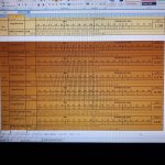
THD was measured at several points, and are shown in tabulated list (attached)
Also the corresponding THD spectra at 1.3W and 2.5W output (1kHz i/p) are shown in the attached screen shots.
Schematic is on the way! (maybe later or tomorrow!)
In the quest to realise reasonable output watts, at reasonable THD, I have made some small changes to the gains of the 2nd triode stage and the pentode stage also.
Also I made a small change to the pentode screen supply, reducing the series resistor to 10k as I believed that the screen was drawing a very low current, even at maximum output.
Currently I measure a max of 1mA screen current, and screen voltage has zero or very little sag at max output; reducing the resistance has increased screen current very slightly.
As it doesn't seem to be doing a lot I may return to the original value, of 24k.
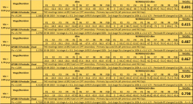
Gains are now as follows:
1st Stage - 6S6B-V triode - 9.5 V/V
2nd Stage - 6S6B-V triode - 5.4 V/V
3rd Stage - 6P30B-R Pentode - 4.1 V/V
THD was measured at several points, and are shown in tabulated list (attached)
Also the corresponding THD spectra at 1.3W and 2.5W output (1kHz i/p) are shown in the attached screen shots.
Schematic is on the way! (maybe later or tomorrow!)
Attachments

Of note to me, from the tabulated data, and the FFT traces (the one I haven't uploaded...), and evident in testing a larger series of points, is the cancellation of 2nd and also sometimes 3rd harmonics.
In this latest iteration, I am really pleased that the THD up at max signal input of 2V p-p (2.5W output) staying so low.
In other iterations of gain structure I have in my notes, I can get lower THD up to perhaps 1W, up to 1.5% at 2.8W.
In each case input sensitivity is ~around the same~
So although the ~0.5% THD doesn't seem great at 200mW, at 1.8W it isnt half bad! This is also the best result for >2.5W I've got, so I'm likely to stay put, for the moment.
Last edited:
Mishaps, observations and maybe I'm learning something!
In my signature I describe my first BIG mistake when I started this mission to make a small tube amp.
Mishap #1
With the bypass capacitor connected in reverse polarity the result was instant runaway. I managed to switch the PSU off in time to save the tube, but it I have 1 6P30BR with a bent up 'plate' with a spot mark, that hasn't burned, just...
In hindsight,
Mistake #1,
Not turning the lights off and stating at the glow of the tubes as I listen for 5 minutes on a small speaker...
On doing the whole staring mesmerized by the glow of the valves I noticed that despite being biased below plate dissipation, one tube had a slightly brighter spot of dull red glow.
Thinking, I reduce the voltage on the variac to lower the overall dissipation a bit, and the situation remains the same, a slight imbalance in the degree of glow.
So...although this pair was matched in a fashion, by their Vg1 bias volts resulting from identical screen and anode potentials.
Clearly they were not matched appropriately, OR I am very close to thermal runaway in one valve.
Perhaps both?
As I am using individual cathode bias resistors on each output tube, I don't think it's current circulation.
Novice I am, I searched for references to runaway in valves. Plenty of useful information here that Android can't manage to search for online in DIYA...
So in my inexperience I selected 1M grid leak resistors for each 6P30B-R valve. This is the dataset maximum.
However on reading into the specific area, I think I will reduce the value to maybe 50-200k and see if that alleviates the issue.
The pair of 6P30B-R are mounted on a rough PCB and perhaps too close together. They are perhaps 2 inches C-C, about a 1.125" gap between them, and they run hot.
I also need to lower filament voltage a smidge.
It could be that I need to select the tubes in a different way for the pairs, until I think of that way, I'll probably roll tubes and watch them in the dark for a bit!
Last edited:
So, I reduced the grid leak resistors for each output pentode by half initially, to 500k.
The same result, one tube slightly redder than the other. So my train of thought is that one tube is more gassy/has higher grid current.
So I switched out the offending tube and replace with one that didn't bias up closely to with the good tube.
After warming up for 5 mins, the tubes are both biased similarly. Which didnt occur before with these two tubes.
My theory here, after some thought, is that the 1M grid leak used previously was causing a very slow build up of grid bias voltage. Or rather, a slow stabilisation of grid voltage. Also it may have exacerbated the differences in grid bias voltages observed.
With the reduced grid leak resistance of 500k the stabilisation is quicker, and both tube bias within 0.6V
What's better is there is no red patch, just a very dull barely visible red evenly across the plate, which makes me feel far happier about the longevity of the tubes.
Last edited:
Very interesting regarding the grid leak resistors. Following your experiments closely as I have several 6P30B-R tubes that I will experiment in both SE & PP configurations.
Hi Gezza,
Thinking some more, I could just have a duff tube. Using the original set I get slightly better gain, and after changing out the 'bad tube, I have slightly reduced gain.
It's something like 4.3V output from OPT down from 4.5V.
Eyeballing of the THD figures I took earlier, they are slightly different, 2nd harmonic is down below 3rd for the majority of measurement points I've chosen.
Until I've typed them into my Excel sheet calc I don't know the percentage value, but it's certainly still pretty good.
I'd estimate 1% at max output.
I also tried 250k grid leak on each output tube, but as I have a pair in parallel, the combined resistance may be on the limit, and THD was worsened. Probably up to 2% or more at max output.
As far as PP goes, part of me regrets not going that route!
Working with these tubes I believe that they may be better suited to PP class AB or B.
I am also tempted to wire them for triode connection, but then drive becomes more difficult, and what THDbenefit I might gain, may well be lost in the extra THD generated by the increase gain required to drive the trioded output tubes
Last edited:
Nice 3D construction with those resistors. I do that too, tack on parts without clipping the leads during "experimentation" so I can use the parts again.
It's not quite as elegant as matrix board prototyping or point to point wiring, but it works!
It's been a nice relaxed weekend, especially when I realised I actually had Today as a work holiday!
The THD numbers got typed into the excel calc and THD is about the same level 1.2% at max input signal level.
Output level is slightly down so max power is now 2.3W verses 2.5W.
I guess a slight worsening of THD vs power. I may up gain a touch to compensate. And then remeasure.
The THD numbers got typed into the excel calc and THD is about the same level 1.2% at max input signal level.
Output level is slightly down so max power is now 2.3W verses 2.5W.
I guess a slight worsening of THD vs power. I may up gain a touch to compensate. And then remeasure.
Attachments
So, for now, the circuit is pretty much done.
I am sure it needs some work to improve performance, and in a spare minute or two today I was able to check the amplifier response to square wave input signal at 1kHz up to 10kHz.
When I get some more time I'll take a screen shot to illustrate,
But verbally, I see some slewing or ramping of the positive wavefront, which once at high state has some small amplitude ripples. The decay part, negative going transisition is not slewed.
I think this may be some signs of marginal stability, although I'm not sure.
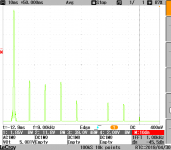
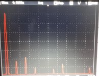
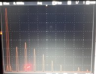
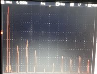
FFT shots at 0.7W, 2.7W and beyond
I figured I haven't uploaded any shot of FFT results, just the calculated percentage THD.
So here are a couple of shots:
At 0.7W
At 2.7W
And the onset of heavy THD going beyond 2.7W (taken at 5Vrms output across the 8R load, roughly 3W output)
I figured I haven't uploaded any shot of FFT results, just the calculated percentage THD.
So here are a couple of shots:
At 0.7W
At 2.7W
And the onset of heavy THD going beyond 2.7W (taken at 5Vrms output across the 8R load, roughly 3W output)
Attachments
- Status
- This old topic is closed. If you want to reopen this topic, contact a moderator using the "Report Post" button.
- Home
- Amplifiers
- Tubes / Valves
- SEP using 6P30B and 5744WB/6C7B