Square waves.....
So today I had a little time to attempt to improve the square wave response.
A little reading and thought and I guess that the spewing of square waves is an indication of HF attenuation.
Presently I have removed the small of caps across grid and ground, since my Ri is quite high, 100k.
Frequency response measured at the secondary of the OPT, extends to 40kHz at -6dB, so it doesn't immediately appear as if frequency response is severely compromised.
I guess, again, that if my response extended to 100kHz, then square waves would look better, but I'm slightly uncomfortable extending it THAT far, if unnecessary to do so for high fidelity.
I'm thinking of checking the square wave response at the primary, and see what difference that shows, if any.
Besides this, I spent some time "matching" valves, and then switching a device for one from another pair, and comparing THD, and DC OP.
I figure the "bad" valve from before, that showed premature red plate, was damaged in testing during Mishap #1, and therefore doesn't perform quite the same.
The THD results are interesting in their trend. Below about 1W or so, THD shows 2nd lower than 3rd and indeed the 2nd is pinned down at -30dB for much of the span of power this amplifier is delivering in tests.
Only in the last Watt of output, does the cancellation drop off, and 2nd rises again but at a comparable amplitude to 3rd (say +/-5dB).
This is seen in waves of cancellation in 4th and 6th (also 8th and 10th but lesser extents) as the input voltage is swept upwards through the entire input signal voltage range.
I liken it to the nodes and anti-nodes in a string, or pipe.
I've read that GNFB is the only way to reduce the odd harmonic content, and since I've tailored this amplifier pretty well for the intended gain/FB, I'm loathed to change it all!
The most trying thing is IRON
So I'm still really new to designing and building with valves, but I think that the hardest thing so far has been making the OPT work well with the circuit.
I thought I'd need 4k, maybe a touch more, based on a few things I've read.
So I buy a 4k/5k OPT and in the end with a single valve, I need to use the 4 Ohm tap with 8 Ohm load, to make a 10k primary.
This is about as optimal as I can make it.
So now I have a parallel pair and the obvious though occurs
"I can now half the OPT primary Z"
Use the correct tap for the load.
Well no
The optimum is still the 10k. Switching to the 4k tap (8k) and THD increases by more than double. Output is slightly increased.
So gain is better, THD worse. Same old see-saw.
Maybe...seeing as the OPT are rated for 60mA DC (5W output), then I might make the effort to parallel 3 valves in the output stage...(each is biased at about 18mA)
So paralleling two plates together parallels ra (rp) right?
Maybe not quite. I guess circulating current, however small, could make the paralleled ra' appear larger. I don't have the background to know much more at the moment.
Either way, it will be interesting to know whether a paralleled set of 3 will allow me to use a lower tap on the OPT.
I'm thinking that a 3W at less than 1% THD would be quite ample for desktop or study levels of volume, with enough to turn it up a little when needed.
So far I've only one channel, and one tiny speaker 86dB at 1W and I'm about 1m away.
Using a mobile device for music, I know I'm not at full volume, and it sounds clean enough to me!
I'm the absence of a curve tracer
Well, I considered trying to make a curve tracer to adapt a oscilloscope, but I've not quite got my head around it all yet.
Best I can figure is if I match on THD then regardless of how the Vg1 volts end up, the curves of the valves are close to aligning or being parallel.
I could adapt to adjust Vg1 on each valve, and it could be a wasted effort, or have the effect if ruining the previous "matching".
Back to ra, or perhaps more correctly Gm
Back a couple of posts I remarked that 2 valves in parallel, should be approximately half the ra of a single valve.
More correctly, Gm roughly doubles. (I haven't measured it)
So for a parallel triple, Gm roughly triples.
Which got me thinking about stability, and the impact Gm may have.
Surely excessive Gm will lead to instability?
But what exactly is excessive?
Meanwhile, while considering this question, I have managed to get through just over half of my stock of 6P30B-R, matching pairs by THD.
Whilst I haven't finished, I'm far enough along to see some trends in results, hopefully I'll have the results in Excel and %THD calculated today.
Then a listen, again.
Well my heater wiring is poor, being a test setup.
I twisted the AC wiring as best I can (3 twist or 4 per inch), but I have a lot of hum.
Seeing as I haven't tried D.C. heater supply, I thought I'd give it a go, and set DC volts slightly lower than usual at 6V.
Listening again, almost all of the hum is gone, what remains can only be heard with my ear within 6".
So I'm happy, and satisfied the circuit isn't itself too noisy, though white noise isn't amazing, and is now more noticeable.
As far as PSU noise, just doing a quick check with AC meter, I read a minimum PSU ripple of 60mV and with less resistance in the RC filter (to support a higher load) a maximum of 140mV. This is whilst the amplifier is driven to max output, 2V p-p input signal.
Not stellar, but not bad considering my lash up.
The 1kHz test tone can clearly be seen modulating the 100Hz ripple.
I should take some scope shots of that too!
It's been a while
I havent got around to playing with this circuit in some time, due to work and a few things that needed repairing at home (guitar amp), the school holidays starting for my eldest, and random speaker purchases.
I have been trying to match valvesin a fashion by quiescent current with regulated g2 of 245V and LED bias at about 35V. The spread is mainly about 16mA to 20mA with B+ of 300V loaded. Some radical outliers at 10mA and 27mA. This is over a sample of 18.
I've started a strip board layout at home in the wee hours with 3 valves in parallel (the OPT is rated for max 60mA DC) and best running is about 17-19mA quiescent bias per valve under the same B+ of 300V, and Vg2 = 245V.
Today, I removed the LED bias circuits, and replaces them with 10 turn pot and bypass capacitors, and fitted a median valued matched pair into the current aged looking board! With an additional 10R resistor in each cathode, I can now balance cathode currents.
A quick THD run at what I'd call max power, before the upper harmonics take off on the FFT...
Well I got maybe 1.5% (F1 26.5dBm, F2 -10 dBm, F3 -15dBm or in that region) at 4.75V into 8R2, say 2.75 Watts.
Then for curiosity, and since I've matched tubes, i increased each grid leak resistor to 1M again, where I had 500k before, because i thought I had a valve go runaway.
(WELL, It turns out that, the valve that tested at 27mA, it that was the one I thought was running away!) And it probably was!
Anyway, I take another FFT at 4.75V output and it's closer to 1%
Triple tubes
So finally I've had a couple hours to mess about with the three pentode output stage. Output power is up to maybe 3W keeping harmonics -45dB or so down.
Now the OPT needs rethinking WRT reflected primary Z, currently 10k.
First though, I set up the bias on each pentode with 500R trimmers, to about 36V on the cathodes, and let the current fall as it will. I had selected the closest 3 valves from my matching efforts with LED bias, that all biased within about 1 or 2mA, and when self biased, lo and behold the result is just as close. Cathode current is about between 16.5 and 18mA, giving a Pd of about 85% at 18mA.
Back to the OPT and when testing 2nd harm. is cancelled greatly, 3rd dominating at 10dB higher level, montonic thereafter.
I've read recently that this often is the result if reflected impedance being too high
So I used the 5k earthy end and 4k hot end taps, for a mid way Z of 9k, and the THD spectra is more conventional, increased levels of probably the first 5 harmonics, and increased output.
Due to the increased gain, I got lost for a while trying to rein it back in a little, and squeeze anything more from the input stage. Ultimately ending where i started.
I did accidentally discover my THD had almost halved, when my zener regulated input and intermediate stage supply became disconnected at ground, leaving just the dropping resistance from the B+.
In trying to stay under 250V and in datasheet limits, (Va at cutoff 350V so...what the hell?) I used the Zener diode supply, but just using the dropper resistance, the triode supply is 280V and THD vastly improved. Neat.
I write so many asides (soliloquy), but I also got lost experimenting with other triodes notably the 6021, which I had a couple to experiment with. Well, I spent a while trying to bias them and find a sweet spot for THD and gain, and I was disappointed on both counts)
Whilst i wont say it's not possible to attain the same results with 6021, i was disappointed, and it really would need a new design, from the ground up, so to speak.
I guess that either reflected load.of 8 to 9k is about optimal either 3 6P30BR, though I am regretting not making up a 4 valve board.
I need to make up some adapters for either 6P30B-R or the smaller single anode 6P30B which has different characteristics, gm, and biases much cooler on the same supply voltages (likes lower g2 volts)
Last edited:
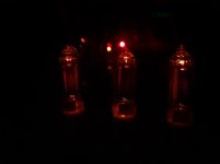
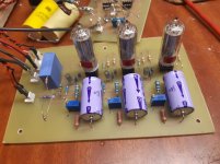
Some photos I'd forgotten
Some red plating showing in the left valve, which interestingly is the biased with the least current, matching cathode voltage to about 0.2V by trimmer resistance.
Perhaps I might drop the current by 1mA and see if that helps this one valve, or switch for another similar match, if I have enough spares from the 6 I would need for a stereo amplifier.
Almost another nail in the coffin for a 3 valve designs to make the most out the 60mA DC rating of the OPT.
I could for example run 4 paralleled 6P30B at 15mA and at less than 75% Pd. Probably good for reliability, not so good for power. I'd probably gain nothing much in terms of power, either way.
But interestingly I have driven the amplifer to a max output of about 3.5W and measured THD under 1%.
What's really interesting is I can no drive beyond max input signal and going up 0.1V results in little change in output, THD spectra shifts, oddly it changes lowernharmonics increase and higher harmonics disappear, and the output just continues to compress.(for THD v Power curve I'd run say every 0.1V until higher up in the curve in 50mV increments, then 25mV.)
Attachments
Last edited:
One thing I keep forgetting to mention in this thread, for anyone interested, and for my own aid to recollection a comment about the 6S6B triode input stage.
Is the 6S6B a so called zero bias valve?
In my tinkering, humming and experimenting I had found the triode input stage anode voltage ended up being biased very much lower.
Previously I had used 27k to 39k Anode resistor on the input stage triode when using the 2 pentode output stage, and this is how I got the lowest THD result, biased at about half B+, so maybe 130V on the 240V supply at the time. Biased at 3.4V eith 2 series LED.
In this instance, presently I have arrived at a anode resistance of 56k-68k and a single LED to give 1.67V at the cathode. What I would think was the minimum headroom for a 2Vpp input signal, where previously I had left lots of room.
Triode plate voltage ends up sitting at about 85V or so with a 280V B+.
Odd as it may be, this operating point gives improvements in both gain and THD measured at the output of the OPT, win win!
Perhaps too, the intermediate stage could be improved, but as it has been for most fo this experiment, biased at 3.4V with 2 LEDs, or at 4V via Ra of 22k and Rk of 820R, anode sits at 150V and THD at the output is the best I can get it.
In the end, bypassed cathode bias works slightly better than LED bias (although to be 100% fair I should add a diode to the LED string, to equalise the bias volts for a equal comparison)
But the sound?
Using the output of my mobile phone and some music, a cannibalised PC multimedia speaker (2 way with 3" woofer) I can say it sounds OK.
As clean as the speakers will play pretty much. Enough enough to drive the woofers to 2 or 3mm travel! Enough to be loud for a small space like an office.
Does it sound totally tubular?
I cant hear any liquid sweetness, or feel the brush of Angel's wing on my face when the amplifer does its thing.
I dont hear any character in particular, which to my mind, is good.
I'll need try out some good speakers very soon, and see what they reveal about any character the amplifer has especially in the bass.
Maybe I should also take THD vs Power at 100Hz and 10kHz (even if the latter case may be less relevant to those without Spidey Sense, like me)
- Status
- This old topic is closed. If you want to reopen this topic, contact a moderator using the "Report Post" button.
- Home
- Amplifiers
- Tubes / Valves
- SEP using 6P30B and 5744WB/6C7B