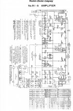
I've got parts and some solid mahogany that have been asking to be made into something, and my imagination keeps returning to the idea of a "statement" WE91A using 6C6 as input (original to the 1938 model) and running the 300B at the WE-sanctioned op point of 400Vak/60mA into a 3K load (11.5W output). It would be respectful of the original yet kind of excessive all at the same time. The design goals would be for a retro artpiece (P2P wired, no silicone or chips) that features the characteristics I've come to like after breadboarding a stereo version of Joe Roberts' abridged 91A from Sound Practices (using 6SJ7).
I like the idea of an imposing appearance, with big transformers and an all-ST tube complement, and using the Hammond 378CX PT that I have (800VCT, 534mA, DCR= 21mA) for a dual mono build. That suggests the following in each channel: 5U4G, 0C3, 6C6, 300B, for a grand total of eight glorious ST tubes.
I’d need a B+ of 496V to pull it off. Playing with LTSpice and PSUDII, just to get a sense of ballpark voltages and feasibility, it can be done safely with a 5U4G rectifier (ST-shaped) in mono, but not when the power supply has the current draw from both channels.
Of course, PSUDII does not allow for modeling two rectifiers and one PT, and I'm not sure how to calculate that situation manually (I usually use the procedure in this article). The current draw from both channels would hit the PT secondary, but each rectifier would be carrying the current of only one channel, so I'm not sure how to calculate the behavior of the PT and what kinds of voltages it would put out. Does anyone know how that would work, or can you point me in the right direction?
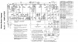
I've attached the original 1938 schematic with 6C6, as well as screenshots of my quick-and-dirty LTSpice and PSUDII experiments.
I like the idea of an imposing appearance, with big transformers and an all-ST tube complement, and using the Hammond 378CX PT that I have (800VCT, 534mA, DCR= 21mA) for a dual mono build. That suggests the following in each channel: 5U4G, 0C3, 6C6, 300B, for a grand total of eight glorious ST tubes.
I’d need a B+ of 496V to pull it off. Playing with LTSpice and PSUDII, just to get a sense of ballpark voltages and feasibility, it can be done safely with a 5U4G rectifier (ST-shaped) in mono, but not when the power supply has the current draw from both channels.
Of course, PSUDII does not allow for modeling two rectifiers and one PT, and I'm not sure how to calculate that situation manually (I usually use the procedure in this article). The current draw from both channels would hit the PT secondary, but each rectifier would be carrying the current of only one channel, so I'm not sure how to calculate the behavior of the PT and what kinds of voltages it would put out. Does anyone know how that would work, or can you point me in the right direction?
I've attached the original 1938 schematic with 6C6, as well as screenshots of my quick-and-dirty LTSpice and PSUDII experiments.
Attachments
Last edited:
Russian and Chinese 5U4G "equivalents" are highly problematic. Can you say arcing?  OS U.S. made 5U4Gs are (IMO) too expensive. FWIW, my attitude is cosmetics be damned and the cylindrical bottle 5U4GB gets my nod. However, there is a pretty good chance that a Chinese or Russian ST bottle rectifier will be OK, into a choke I/P filter.
I don't read Hanji, so could easily be misconstruing things. That 4 μF. on the Chinese datasheet draws my eye. Compare that with the 40 μF. found on the Sylvania datasheet.
Perhaps the best solution to the rectifier issue is the UX4 based/ST bottle 5Z3, which is electrically equivalent to the 5U4G. RES shows a suspiciously low $11 price, which suggests their stock (if any) is the Chinese Octal tube. Definitely inquire, before ordering. AES shows a $24.90 price, for what is clearly the item in question.
OS U.S. made 5U4Gs are (IMO) too expensive. FWIW, my attitude is cosmetics be damned and the cylindrical bottle 5U4GB gets my nod. However, there is a pretty good chance that a Chinese or Russian ST bottle rectifier will be OK, into a choke I/P filter.I don't read Hanji, so could easily be misconstruing things. That 4 μF. on the Chinese datasheet draws my eye. Compare that with the 40 μF. found on the Sylvania datasheet.
Perhaps the best solution to the rectifier issue is the UX4 based/ST bottle 5Z3, which is electrically equivalent to the 5U4G. RES shows a suspiciously low $11 price, which suggests their stock (if any) is the Chinese Octal tube. Definitely inquire, before ordering. AES shows a $24.90 price, for what is clearly the item in question.
Last edited:
......]Of course, PSUDII does not allow for modeling two rectifiers and one PT, and I'm not sure how to calculate that situation manually .......
1) double the transformer resistance, sim for one channel
2) PSUD *does* have "multiple rectifiers" (at least the current version). Use "5U4-GX2" which is a double 5U4-G. (Not all bottles available in multiples, so #1 trick still handy.)
3) You can plot it out on the 5U4 curves. G.E. often has good info. Interestingly you *can* run one 5U4 for both channels-- as I thought, because it is in-sight of many happy amps I have known. To hit your goal you want a little more AC voltage, and more DCR......
There is not a "Maximum cap". Any practical size can be used IF there is sufficient winding or added resistance. The "40u" on the Sylvania is clearly "typical", not "Rated". They also give typical "effective plate supply impedance", but the G.E. sheet gives values for the various AC voltages. For 400VAC they suggest 52r; you should add a 33r to your transformer. (With dual rectifiers I would put 32r in each plate, to also tend to current-balance.)
Yes, reading Chinese might be interesting. However the *oldest* datasheets for 5U4 or its 4-pin father did cite 4uFd, because that was a "big" capacitor at the time. Note also the "2K ohms".... I wonder what that means?
Attachments
Thanks, Eli and PRR. 5U4GB is in my stash and an incredible workhorse, so that's totally possible. And it's what I used to breadboard the 91A last year as well as a number of other 300B circuits.
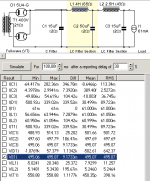
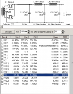
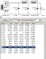
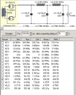
Using PRR's "first trick" of doubling the PT secondary DCR, using 5U4G, and keeping all else as if mono, I get 491V B+. So, I just need to find a way to squeeze ~4.5 more volts out of it.
Replacing the 4H/65R choke (Hammond 159S) with another 2.5H/43R choke (Hammond 159T), brings it to 493V but the ripple increases to 14.9mV.
Playing with the input cap value can bring it even closer to 496V with lower ripple. A 50uF input cap gets a ~494.6V B+ with ~4.5mV ripple, but that's higher than the "usual" 40uF input cap as per the Tung-Sol datasheet.
EDIT: I'd been using the mfr. published specs for the chokes in LTSpice. I just measured my two 159T chokes at 39R (not 43R), which raises the B+ in PSUD2 to just under 494V. So, who knows -- the real thing could be spot on (or further off) when breadboarded. The 378CX DCR of 21R was measured, btw.
Attachments
Last edited:
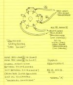
Does anybody know what size grid cap to use for the 6C6? The datasheet says "small metal," and I measure the cap at about 3/8" diameter. Online retailers don't seem to use a common nomenclature and 6C6 is never listed as one of the "compatible" tubes in the lists.
I see 310A listed as using 9mm plate caps, which is just about 3/8".
I see 310A listed as using 9mm plate caps, which is just about 3/8".
The (IMO) easy way to squeeze some extra "height" out of the B+ rail is by employing 5AR4s. Up to 60 μF. as the 1st filter cap. is safe and the type exhibits the smallest forward drop among commonly used 5 VAC vacuum rectifiers.
OS 5AR4/GZ34 stock is costly. Affordable current production Sovtek 5AR4s are highly satisfactory, provided the series SS diode tweak is implemented. FWIW, I suggest using UF4007s, instead of the 1N4007s shown in the graphic. The idea is that vacuum rectifier noise suppression or not, less switching noise, from the outset, is better.
OS 5AR4/GZ34 stock is costly. Affordable current production Sovtek 5AR4s are highly satisfactory, provided the series SS diode tweak is implemented. FWIW, I suggest using UF4007s, instead of the 1N4007s shown in the graphic. The idea is that vacuum rectifier noise suppression or not, less switching noise, from the outset, is better.
Attachments
...So, I just need to find a way to squeeze ~4.5 more volts out of it.....
Seriously? 1% shy is a problem??
Wall voltages vary +/-5% all day long, many places; worse in other places.
Hammond's good-old designs are wound for lower wall voltage than most outlets give today.
1% shy on voltage is <0.1dB reduction of maximum output which is quite insignificant. Especially on an amplifier which does not have a sharp "CLIP!".
Use two 5U4 for visual symmetry and because you have them (I don't think the few volt difference matters). Use 33r 2W in each plate feed.
The schematic is a mess, like that no purpose at allBack to the schematic, why the decoupling on U1's grid resistor - C5? And also what is the purpose of R11/12 and C8 please?
Andy.

Cleaned it up a little, but not my idea
Mona
Attachments
If you are going to use a separate rectifier for each channel, 5V4G and 5R4GY present the same ST look, and may be easier ( cheaper ) to source. Both will have a higher voltage output than 5U4G, which may or may not be to your advantage.
For the cold steel industrial look, there is 5T4. These are very inexpensive; all are RCA, AFAIK.
Win W5JAG
edit: whoops, you'll see about 10 volts less with 5R4 - not sure what I was thinking ...
For the cold steel industrial look, there is 5T4. These are very inexpensive; all are RCA, AFAIK.
Win W5JAG
edit: whoops, you'll see about 10 volts less with 5R4 - not sure what I was thinking ...
Last edited:
Fair enough. I was just trying to go through the exercise of figuring ways to adjust voltage. The real thing will be different when breadboarded anyway.Seriously? 1% shy is a problem?? Wall voltages vary +/-5% all day long, many places; worse in other places
I understand that SS rectification is more efficient but prefer the sound of tube rectified circuits, plus part of the goal is to respect the original design.This may be a bit controversial but why use a valve rectifier in the first place, surely SS rectification and a big cap is better for SE PSU?
I think these are bleeder and AC shunt circuits. They are there because I don't wish to alter the original topology, which sounded great when I breadboarded it before.Back to the schematic, why the decoupling on U1's grid resistor - C5? And also what is the purpose of R11/12 and C8 please?
Thanks, Win. I will play around with these in LTSpice & PSUD2 to see what happens.If you are going to use a separate rectifier for each channel, 5V4G and 5R4GY present the same ST look, and may be easier ( cheaper ) to source. Both will have a higher voltage output than 5U4G, which may or may not be to your advantage.
And thanks also to kstagger and Eli for suggesting 5Z3. Will play with that too.
C5 and R9 does not serve any purpose any more. It was filtering for the input tube B+ in the original schematic. Take them out, then: Connect the bottom of the 390k Ohm grid resistor to the bottom of the 300B self bias resistor and bypass capacitor.
15uF seems a little low for filtering the B+ that goes to the bottom of the primary of the 300B output transformer. a 15uF cap has 530 Ohms of capacitive reactance at 20 Hz. If the output transformer has a 3000 Ohm primary, you have a 3000/(3000 + 530) Ohm divider (transformer impedance plus B+ impedance) driven by a 300B rp of 700 Ohms. I am being very conservative here, because you will have very few 20Hz musical notes, but a Bass Electric guitar goes down to about 40 Hz where the 15uF capacitor reactance is 265 Ohms. The series circuit is 700 Ohms, 3000 Ohms, 265 Ohms @ 40 Hz. We are not just trying to conquer 100 Hz or 120 Hz ripple, we are trying to provide low impedance at bass frequencies.
15uF seems a little low for filtering the B+ that goes to the bottom of the primary of the 300B output transformer. a 15uF cap has 530 Ohms of capacitive reactance at 20 Hz. If the output transformer has a 3000 Ohm primary, you have a 3000/(3000 + 530) Ohm divider (transformer impedance plus B+ impedance) driven by a 300B rp of 700 Ohms. I am being very conservative here, because you will have very few 20Hz musical notes, but a Bass Electric guitar goes down to about 40 Hz where the 15uF capacitor reactance is 265 Ohms. The series circuit is 700 Ohms, 3000 Ohms, 265 Ohms @ 40 Hz. We are not just trying to conquer 100 Hz or 120 Hz ripple, we are trying to provide low impedance at bass frequencies.
Last edited:
I am being very conservative here, because you will have very few 20Hz musical notes, but a Bass Electric guitar goes down to about 40 Hz where the 15uF capacitor reactance is 265 Ohms.
A "standard" double (upright) bass goes down to 41 Hz. There are variants that go even lower. A contrabassoon gets down to around 29 Hz. FWIW, the Atlantic City Convention Center organ was built with a 64 foot stop that "sounds" in the (sic) infrasonic range.
BTW, most of the energy of a bass guitar's lowest note is in the 1st overtone, not the fundamental.
Eli,
My point was to say that there might not be very much low frequency bass response with just the 15uF cap.
Yes, of course there are lower frequencies than an electric bass guitar. The 6 Hz canon of the Telarc recording of the 1812 overture, for one. But many consumer hi fi speakers do not even produce 41 Hz at full strength.
It is interesting that some bass guitar amps and some guitar speakers attenuate the 41 Hz tone. But those same amp and speaker combinations produce 2nd, 3rd, and 4th harmonics . . . , etc (plus the plucked string produce those harmonics too). But ears can be fooled into "hearing" the fundamental tone. That is because all the harmonics are spaced evenly by 41 Hz from one harmonic to the next. You could call that a fooled ear, or you could call that smart processing by the brain.
It is possible to enjoy music reproduction even though it is not 100% accurate, yes?
Last edited:
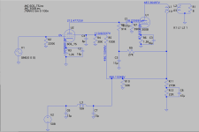
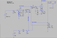
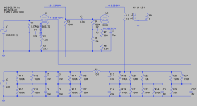
Just to get a better visual of the original schematic, I drew it up in LTSpice, minus the plate meter, first input stage (and the feedback loop to the screen there), and the power transformer (using a DC voltage source instead).
It's interesting.
The only inductance in the power supply is the voice coil of the projection room monitor (L3 in the LTSpice drawing below). I'd have to do some research to find that value, so I arbitrarily put 10H there for now.
The only series resistance in the PS is the DCR of the monitor, the 10K (R22) dropping resistor that leads to the 6C6's 100K plate load resistor, and the 150K (R27) screen grid dropping resistor.
For this model, I calculated a DCR of 1073 ohms for L3 to get the 300B voltages to match what's in the original schematic (operating it at 350Vak/80mA). The 6C6 voltages are slightly high on the screen (115V instead of 110V) and low on the plate (125V instead of 150V), but WE indicates these are nominal voltages.
I had thought I might breadboard the Sound Practices WE91A again, just to get a reference point for subsequent iterations, and then try the original schematic. I suppose I could do it with a standard 10H (or so) choke, adding resistors to the filter stages on either side of it to get the required voltages.
Anyway, just thought I'd post the schemos here incase there's interest.
Attachments
Last edited:
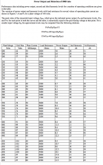
R (Lim)= R (Pri)+R (Sek)*(V-Sek/V-Pri) squared So you have to measure your tranny first in real life.
The first cap should be the smallest as the first coil should be the smallest value, too. That improves details in sound. 300B will benefit greatly from a real punchy driver, Shindo uses WE 349 power tube and that has some reason.
The original design has too much gain and with its whimsy 310B driver tube its not the best in the world, but otherwise it is a decent design without mistakes. WE knew their stuff.
So in my opinion and listening experience, I would mod this for one WE 310A and a decent driver for the 300B. Soundwise, I like the 5R4G more ,even Shindo uses this model instead of 5U4G. He has switched at some point of the 40 year old heritage in building his 300B SET amps. And I would not go beyond 8W output power. If you have the right speakers, nothing more is needed.
P. S. L'audiophile did your design, too.
Last edited:
I'm circling back to this project and ready to begin breadboarding soon. If I want to get the full 8-10 watts of output power across the audible spectrum, how would I figure out what wattage rating is needed for a 3K:8ohm output transformer?
I see that OPTs for 300B SETS from outfits like Magnequest (FS-030) and Hammond have power ratings in the 30-40 watt range.
I see that OPTs for 300B SETS from outfits like Magnequest (FS-030) and Hammond have power ratings in the 30-40 watt range.
Bandwidth: A single ended transformer that easily puts out 30 Watts at 1 kHz is not going to put out 30 Watts at 20 Hz. That is because it will saturate at 20 Hz.
For a single ended transformer to put out 8 Watts of power at 20 Hz, it will need lots of laminations, and lots of primary turns (lots of inductance).
Insertion loss: A 3,000 Ohm to 8 Ohm single ended transformer that has 150 Ohms primary DCR and 0.4 Ohms secondary DCR will have a 1 dB insertion loss. 10 Watts of 1 kHz signal from the 300B into that transformer will be 7.94 Watts into an 8 Ohm load.
10 Watts rms Power = I x E Root (P x R) = E Root (10 W x 3000 Ohms) = 173V rms 173V rms x 1.414 = 244.6V peak 244.6V peak / 3000 Ohms = 81.5 mA With a quiescent current of 81.5 mA into 3000 Ohms, and a current swing of from 0mA to 163 mA, we would get 10 Watts into the primary. That would be 8 Watts out of the secondary of a 1 dB insertion loss transformer. But a 300B can not linearly put out current from 0mA to 163 mA.
We could use a quiescent current of 91.5mA, and a +/- 81.5mA current swing of from 10 mA to 173 mA.
We will still need 244.6V peak swing, or 489.2V peak to peak to get 8 Watts out of that transformer.
The mu (u) of the 300B is 3.85. The 300B rp is 700 Ohms. The gain is u x (3000/(3000 + 700)) = 3.84 x (3000/3700) = 3.84 (0.81) = 3.11
We needed 244.6V peak swing. 244.6V/3.11 = 78.6V We need a grid bias of -78.6V, because the gain is 3.11. The driver stage has to provide +/- 78.6V, or 157.2V peak to peak.
It is not an easy task to get 8 Watts rms out of a 300B amp. Actually, the 300B has 2nd harmonic distortion, so the plate current will go to about 2x the quiescent current (2 x 91.5 mA, 183mA). That 2nd harmonic energy should push us over the top to a little more than 8 Watts at perhaps 5% distortion.
I hope I did not make an error in the math at this late hour.
Last edited:
- Home
- Amplifiers
- Tubes / Valves
- WE91A 6C6