Thanks for all this, 6A3sUmmer. I'll work through all that this week to make sure I understand it.
I picked up some 0C3 at the hamfest a couple weekends ago, thinking I'd use them to regulate the screen voltage on the 6C6. However, now I'm not sure that's possible because the 0C3 requires a minimum 5mA of current @ 133V, while the screen current of the 6C6 is 0.5mA. My understanding is that I'd need a resistor from the supply voltage in series with the 0C3 to provide a voltage & current within the operating window of that tube. So will the 6C6 screen still draw only 0.5mA if the 0C3 is "set" at 5mA?
I've never used a gas regulator before so I'm totally unfamiliar with this.
... If I want to get the full 8-10 watts of output power across the audible spectrum, how would I figure out what wattage rating is needed for a 3K:8ohm output transformer?
...? Look for one with the specs for power and FR you want? Output power is how they are generally rated.... Just pick the power headroom and cost you want. Is it more complicated than that?
more info on using gas regulators including calculations:
Basic VR Tube Regulator Circuit
I use 'em for regulating the screens of pentode outputs. And drivers (if I have enough available VR current). If necessary you could - waste of power! - put a resistor in parallel with the gas tube to draw the extra needed current.
Basic VR Tube Regulator Circuit
I use 'em for regulating the screens of pentode outputs. And drivers (if I have enough available VR current). If necessary you could - waste of power! - put a resistor in parallel with the gas tube to draw the extra needed current.
jdrouin,
kstagger beat me to the punch. But here is something tailored to your requirement:
The 6C6 maximum rated screen voltage is 125V in pentode mode. In Triode mode it is 250V maximum. But you should be able to run the screen at 133V in pentode mode, as long as all the other operating conditions are well within their maximum ratings (plate dissipation, plate voltage, screen dissipation, and filament voltage).
Or, you can use a 105V regulator tube. OB2, OC3, OC3A The 6C6 data sheet shows pentode applications with 100V screen supply.
Just choose either 105V or 133V.
Here is an example of how to use the OC3 to regulate the screen of your 6C6: Suppose you have B+ of 300V, and you want to drop the voltage down, and regulate it to 133V for the 6C6 screen.
6C6 screen 0.5 mA, plus OC3 min 5 mA, equals total: min 5.5 mA
But you need to allow for some variance in the 6C6 screen current, both quiescent, and when signal is applied; And you need to allow for variance in the OC3 minimum current. And you need to allow for variance of the 300V B+.
Lets use 8 mA current to run the 6C6 screen and the OC3. That has a 2.5 mA safety margin.
300V - 133V = 167V 167V / 0.008A = 20.875k Ohms. 167V x 0.008A = 1.34 Watt Use a 20k Ohm 5 Watt resistor.
Connect one end of a 20k resistor from +300V, and the other end of the 20k resistor to the junction of the OC3 plate and 6C6 screen. Connect the cathode of the OC3 to ground. Done!
But what if your B+ is 200V? 200V - 133V = 67V 67V / 0.008A = 8.375k Ohms Use an 8k 2 watt resistor. Done
OB2 at 105V B+ 250V 250V - 105V = 145V 145V / 0.008A = 18.1k Ohms, use a 20k 5 Watt resistor.
The numbers change when you use another tube with more screen current.

plus part of the goal is to respect the original design.
By taking out the feedback and the input stage, it is no longer a model 91 design. Part of the sound of Western Electric amps is the use of feedback from the output tube's plate. Actually many WE amps use feedback, contrary to the doctrine of the single-ended crowd. I understand the excessive gain issue. I just don't believe in breaking apart or deleting the global feedback loop and still able to retain the sonic signature. You will get a fine amplifier using your schematic but that's not the sound of 91 anymore.
Re-creating the "sound" of the old WE91 requires lots more than original output transformers and other original parts. You need an old original movie projector, old original film movies, and old original theater speakers that were used on the '91, right?
Build 're-creations' as close as possible, and enjoy the listening. But do not expect to re-create what it was like in the 20s and 30s. That was a different time. Example: when I attend the various decades (20th, 30th, 40th, 50th . . .) of high school re-unions, I enjoy them, getting updates on people, and remembering the 60s. But I can not really go back to all that life was then.
Build 're-creations' as close as possible, and enjoy the listening. But do not expect to re-create what it was like in the 20s and 30s. That was a different time. Example: when I attend the various decades (20th, 30th, 40th, 50th . . .) of high school re-unions, I enjoy them, getting updates on people, and remembering the 60s. But I can not really go back to all that life was then.
Last edited:
Hi jdrouin,
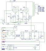
Have you seen Thorsten’s version? I attached the schema (was a kit amp over a decade ago).. I’m not sure though if lowering the heater voltage for the 6C6 is the only change needed since the design had a NOS 310A in mind.. I’m also wondering if one can change the 274A rectifier to a more common 5R4G would be feasible with a similar PSU arrangement, with only some adjustments to the dropper resistors. There are Chinese reproductions of the WE driver pentode and rectifier made these days, but I’m not sure about their reliability.
Have you seen Thorsten’s version? I attached the schema (was a kit amp over a decade ago).. I’m not sure though if lowering the heater voltage for the 6C6 is the only change needed since the design had a NOS 310A in mind.. I’m also wondering if one can change the 274A rectifier to a more common 5R4G would be feasible with a similar PSU arrangement, with only some adjustments to the dropper resistors. There are Chinese reproductions of the WE driver pentode and rectifier made these days, but I’m not sure about their reliability.
Attachments
6C6 screen 0.5 mA, plus OC3 min 5 mA, equals total: min 5.5 mA
Thanks, 6A3. That's what I was looking for. I didn't know if the regulator would dump 5mA into a screen rated for 0.5mA, or if they would sum together to draw 5.5mA from the PT. So, no problem there. Easy enough to use the standard equations to figure out a safe current value for the regulator and determine the resistor value, as you showed above.
6A3 & directdriver -- Re: re-creating the sound of the WE91A -- I can't really do that, since I never heard an original. I just meant that I wanted to maintain the original topology as far as possible. Though here I am trying to use gas regulators where they weren't, and I've already altered my thinking on the power supply and the op point of the output stage.
fred76: I picked up a pair of 5Z3, which should allow me to get the voltages needed to run the 300B at 400Vak. In previous 300B SETs I've built, I liked the sound better the closer the tube got to 400V. I'd like to try the WE-sanctioned op point of 400Vak/50mA (bias -89V) into a 3K load, but will test a bunch of them before picking.
On PSUDII I've been playing around with power supply filters. Looks like I should be able to get to that op point with a CLCLC filter using two Hammond 159T chokes (2.5H, DCR = 39 ohm measured by my Klein DMM) in each channel. With caps at 15uF, 50uF, and 25uF, simulated ripple is 7mV, which should be pretty negligible considering the nearly 500V HT supply and then the step-down through the OPT.
What's the purpose of capacitors C2 (1uF) and C4 (20uF) that go from the bottom of the grid leak resistors to the cathodes? Local feedback? A shunt to circumvent internal Miller effect?
Reattaching my redraw of the original schematic for convenience.
Attachments
jdrouin,
C4 is nothing more than a cathode bypass cap that is across the self bias resistor. You duplicated the WE drawing that drew the return sideways to the grid resistor lead that is going to ground, instead of drawing C4 direct to ground. Looks different, but it is the same at audio frequencies.
C2, your guess is as good as anybody else's. And so is the 10k Ohm resistor that it bypasses.
By the way, unless you are planning on using a crystal phono cartridge as the signal source, you need to use a grid leak resistor lower than 2.2 Meg Ohm for the input tube. 2.2 Meg Ohm, and old tubes may cause the total bias voltage to be anything that it wants to be. Very un-necesary when you have a cathode self bias resistor.
Oh, . . . another signal source that might need a 2.2 Meg Ohm resistor is a film projector that has a photo electric tube to drive audio signal into the input tube.
Actually, the 6C6 tube was designed for multiple applications, including as a grid leak detector; a 2.2 Meg Ohm grid resistor and No self bias resistor would apply to that kind of circuit. That application was used in AM radio receivers to take the modulated RF and convert it to the audio signal.
Any modern signal source that can not drive a 100k Ohm grid resistor needs to be replaced with another modern signal source.
And you can toss out R3 and R8, they do nothing. They may have originally been used as negative feedback nodes, but your schematic does not have negative feedback.
Last edited:
Ah, right. Good eyes on C4. And yes, I was probably just not going to bother with R3 and R8. I might also leave out C2, which isn't in the Sound Practices variant, though I can always breadboard it both ways just to see.
I think the 10K resistor below the 390K grid leak on the 300B is related to the ammeter, which isn't depicted in this drawing -- so that's also a candidate for removal.
Also left out of the drawing is the first 6C6, which picks up the optical sound track from early sound film, since there's no need for two gain stages.
I'll probably replace that 2.2Meg grid leak on the 6C6 with something like 100K. This will be driven by a line preamp, my clone of the Wright WLA-12. In fact, the WLA12 uses the same topology as the voltage amp/cathode follower stage of the WPA 3.5 power amp, which drives a 47K grid leak resistor on the 2A3. So maybe it would be at home with a 47K grid leak on the 6C6 of this WE91A.
jdrouin,
C2, your guess is as good as anybody else's.
And so is the 10k Ohm resistor that it bypasses.
The cathode cap across the 880ohm is too small (16uf) which reduces the 300B gain at low freq. Remember high value cap is bulky and expensive back then and the system will only need to be flat to 80hz. The 1uf bypassing 10k + 880r//16uf act as a dead short between the grid leak to 300b cathode. Around 16hz which is 5T below 80hz. The added bonus is you can use a good quality 1uf cap as compare to high value cathode bypass.
I tends to agree to some practical level that if you ditch all the design principle of 91 amp then it’s your own amp instead. The circuitry, the component values, the freq limited high insertion lost opt all play a big part. And the last thing is, if you will need western electric 300B to know what it’s all about.
Sorry to burst many’s bubbles, I have tested 50s, 60s, 70s, 80s WE300B and own some too. Still none of the modern ones share the magic. Many modern sounds good, technically better in sonic, but still no magic!
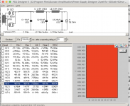
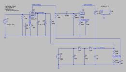
OK, after focusing on cabinetry skills for speaker building for a few months, I'm coming back to this project. I decided to simulate a first iteration of a slightly modified WE91A circuit, incorporating some of the suggestions above, with 6C6 regulated by a 0C3. The sim voltages and current check out pretty well.
In the attached screenshot, the 0C3 appears as a Zener diode because that was the model I adopted from the Spice thread.
My one question is -- Do I risk damaging or destroying the 6C6 by putting a gas regulator on the screen?
A builder who does not participate on this forum cautioned me against putting a 0C3 on the 6C6 screen, because the screen has a max current of 0.5mA and the 0C3 requires minimum 5mA to start. I used R25 to set the 0C3 at 140V & 8mA. The sim has about 0.25mA on the 6C6 screen whether or not the 0C3 is connected.
No one in this thread has cautioned me so far but I wanted to double check before I breadboard it.
Attachments
Last edited:
The large cap in parallel with a gas tube is likely to oscillate.
IMHO, the 0.5mA Ig2 is reasonably steady and uncritical. A divider with 5mA of current is PLENTY stable. It's only audio, not a radar pulse amplifier.
Or is the idea "glow"? Then leave R25=35k, remove R26 and C10. There may be hash from the gas tube into the screen. Then _I_ would fall back to a simple R-R-C divider for screen, leave the gas tube for glow.
Oh right, thanks! Forgot about the need for a maximum 0.1uF bypass cap on the 0C3. I've got a 0.1uF PIO and a 0.0625uF film cap I can try there.
Here's a modified version taking PRRs suggestions into account.
Part of the reason for using VR tubes is to show off the glow. As you note, VR regulation is not really advantageous in the circuit as shown. However, I'm considering running the 300Bs at 400Vak/50mA, which will require a B+ of around 500V. So I thought a VR tube could be a way to keep the proper screen voltage on the 6C6 without a super large resistor there causing sag.
Attachments
And . . . Swap the capacitors that are in C2 and C6. C2, 50uF, put it in the C6 spot. C6, 25uF, put it in the C2 spot. Now . . .
50uF (now in the C6 spot) has a capacitive reactance of 159 Ohms at 20Hz. That is 159 Ohms in series with the impedance of L1 Primary. If L1 primary is 3000 Ohms, that is in series with 159 Ohms of 50uF. ~ 5% At 40 Hz, it is less than 2.5%.
If L1 primary is 3000 Ohms, that is in series with 318 Ohms of 25uf (what is on your schematic now). The B+ impedance of 318 Ohms is over 10% of the L1 primary impedance AT 20Hz. At 40 Hz, 25uF is ~ 5% of L1 primary impedance.
I'm just sayin'.
And yes, I too have used a gas regulator tube and a resistor just to get the glow. I used a 150V OD3 for a nice purple glow.
Last edited:
The original schematic has 150V on the 6C6 plate. The 134V is just what happened when I changed the sim. I didn't do anything beyond that at that point but on the breadboard I would definitely tweak to give it more voltage.The 300 needs a lot of drive. The 6C6 can take a lot more than 134V. Why starve it?
Thanks for the suggested edits to the schemo. I love the glow graphic! 🙂 Would that 700K resistor on the 6C6 screen be likely to cause sag or other issues?
6A3Summer: thanks for the suggestion on PS cap order. Forgive the newbie question, but are you suggesting those changes for the sake of low frequency response? I just wasn't sure what your considerations were aimed at. My PS design has so far been limited to ripple reduction, following the guide available at diyaudioprojects.com, and not other factors, so it's time to read more thorough material on this.
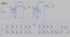
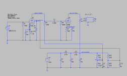
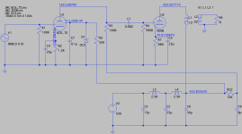
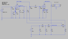
Here are two more versions, incorporating some of PRR and 6A3sUMMER's suggestions.
The 80mA version removing the 135K resistor at R23 results in 160V on the 6C6 plate, just 10V above the 150V in the original WE schematic. Of course, other resistor values can be tweaked for higher plate voltage.
The 400Vak/50mA version, with a supply voltage of 495V and keeping a 0C3 on the 6C6 grid, nets 225V on the 6C6 plate, close to PRRs recommended 250V. A 43K resistor sets the 0C3 at 140V/8mA.
Attachments
> Would that 700K resistor on the 6C6 screen be likely to cause sag or other issues?
Is this a Heavy Metal guitar amp? If not, SE circuits in un-clipped speech/music work don't "bounce/sag". Built it, put a meter on points, push it, the bias points hardly vary.
Is this a Heavy Metal guitar amp? If not, SE circuits in un-clipped speech/music work don't "bounce/sag". Built it, put a meter on points, push it, the bias points hardly vary.
jdrouin,
You will get almost identical ripple voltage reduction with C2 and C6 swapped.
Ripple is at 2X the mains frequency.
50Hz = 100 Hz ripple
60Hz = 120 Hz ripple
But . . .
The lowest note you might want to play through your amp might be:
83 Hz lead guitar
41.5 Hz bass guitar
32.7 Hz organ Pedal C
16 to 25Hz Thunder drum
The impedance of a capacitor is higher as you go to a lower frequency. You want a stiff capacitor at low frequencies that supplies current to the 300B and output transformer.
When the capacitor impedance is 10% of the output transformers impedance, you are about 1 dB down. If the RC coupling is also 1 dB down at the frequency, and if one of the bypass caps is 1 dB down at that frequency, You are now -1 dB + -1 dB + -1 dB = -3dB down at that frequency.
A little rolloff here, a little rolloff there, and pretty soon you are talking about 1/2 power (-3dB).
Most speakers will not go that low, but add the -1, -3, or -6dB frequency of the speaker to the amp rolloff.
Last edited:
- Home
- Amplifiers
- Tubes / Valves
- WE91A 6C6