Thanks for the explanation, 6A3sUmmer, and for building the circuit, PRR. Much appreciated.
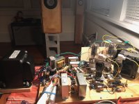
I just breadboarded the first variant of this project, starting with the original schematic as close as is reasonable given the space constraints of my breadboard and the parts I have on hand.
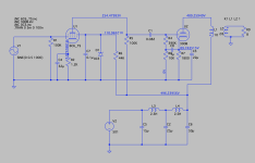
Instead of a .04uF coupling cap, I'm using a .039uF PIO pair I found locally. For the doubled resistors in the 6C6 screen and plate supply, I used a single resistor of their equivalent value. Also I couldn't find any 135K resistors in place of the twinned 270K, so I put a 120K and 15K in series. These are all reflected in the attached schematic.
The channels split at C7.
B+ 439V
300B plate 429V
300B cathode 72.5V
356Vak/82.3mA
6C6 plate 150V
6C6 cathode 3.5V
6C6 screen 113.5V
I calculate the LF cutoff at the 300B grid to be 159,155 / 400,000 / .039 = 10.2 Hz.
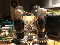
These are new OPTs (Electra-Print low-IMD 3K:8R, 100mA, 30 watt) and NOS coupling caps, so they'll need break in time, but it already sounds very good. Speakers are self-made Planet 10 trapezoidal Onkens for Mark Audio Alpair 10P.
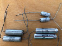
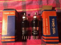
I love the smoked glass Tung-Sol 6C6 (also NOS) and the silvery caps I found at the store. They remind me of early Jet Age aircraft.
I just breadboarded the first variant of this project, starting with the original schematic as close as is reasonable given the space constraints of my breadboard and the parts I have on hand.
Instead of a .04uF coupling cap, I'm using a .039uF PIO pair I found locally. For the doubled resistors in the 6C6 screen and plate supply, I used a single resistor of their equivalent value. Also I couldn't find any 135K resistors in place of the twinned 270K, so I put a 120K and 15K in series. These are all reflected in the attached schematic.
The channels split at C7.
B+ 439V
300B plate 429V
300B cathode 72.5V
356Vak/82.3mA
6C6 plate 150V
6C6 cathode 3.5V
6C6 screen 113.5V
I calculate the LF cutoff at the 300B grid to be 159,155 / 400,000 / .039 = 10.2 Hz.
These are new OPTs (Electra-Print low-IMD 3K:8R, 100mA, 30 watt) and NOS coupling caps, so they'll need break in time, but it already sounds very good. Speakers are self-made Planet 10 trapezoidal Onkens for Mark Audio Alpair 10P.
I love the smoked glass Tung-Sol 6C6 (also NOS) and the silvery caps I found at the store. They remind me of early Jet Age aircraft.
Attachments

Last edited:
Congratulations, you got the amp running.
In your latest schematic: Your filter cap that feeds the 300B output transformer primary is 15uF. The 300B plate resistance, rp, is 700 Ohms. The 15uF cap is 265 Ohms at 40Hz, or 530 Ohms at 20 Hz. 265 Ohms is a large percentage of 700 Ohms (almost 30%). You may want to increase the filter cap's capacitance.
Or you may choose to leave it at 15uF. Most voice of the theater start cutting off at about 45Hz. And the original films recordings probably did not go below that either.
Last edited:
Thanks. I breadboarded the Sound Practices version of the circuit a couple years ago and loved it. With 6SJ7 it had lots of drive, and became much less polite (and a lot more fun) when I changed the op point of the 300B to about 380Vak/56mA.
The current circuit is just to hear what a close-ish rendering of the original schematic would sound like, to form a baseline for comparison. I’ve got 47uF caps that’ll go into the PS pretty soon. Also a larger coupling cap would probably help. But some of these components need a little break-in so I’ll just play it for a few days and then start fiddling.
Streaming a station based around Joe Pass. This circuit is damned fine.
Attack, decay, instrument timbre. Just wow. Bass is copious and very well defined.
What do we think of this simplified version, which runs the 300B at 400Vak/50mA and uses 0C3 on the 6C6 screen?
===
This version eliminates the separate dropping/filter sections for the 6C6 screen and plate, using the 50uF capacitor at the end of the power supply. It also leaves the 1uF bootstrap on the 300B in place, though I'd be tempted to remove it.
Attachments
I've got a pair of 5V transformers that have center taps on the secondary side, which I've never seen before. Each 5V transformer will power the filaments on a 5Z3. Can I run the center tap wire to the reservoir capacitor in the power supply, or should I run it from a filament pin on the 5Z3?
Seems like you should be able to use the CT wire but not sure if that would put too much DC voltage through the windings.
Seems like you should be able to use the CT wire but not sure if that would put too much DC voltage through the windings.
Curious were you ended up with this and if you ever built it? Also, would you mind sharing the LTspice file?
Thanks
Mark
Thanks
Mark
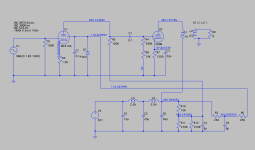
New question: In the original design, why is the screen bypass capacitor for the 6C6 so big? In tube manufacturer resistor charts and for most designs out there, the screen bypass cap on an input pentode is typically 0.1uF or lower, but on the WE91A it's 8uF.
The screen network (circled in red) seems to be a voltage divider that sets the screen voltage and acts as an extension of the power supply filter. But my understanding is that caps above 0.1uF at that position typically run the danger of sending the tube into oscillation.
Sorry blueglow, I didn't see your response until just now. I built the 6C6 version on a breadboard, which worked great. I have many LT Spice files for this project now. Let me look through them for the ones that will be most helpful and will post shortly.
Attachments
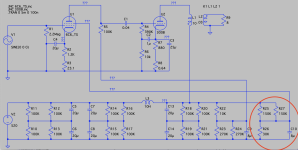
It is there to rid of the hum on the power.The low value of R26(30k) makes the need for a langer capacitor.New question: In the original design, why is the screen bypass capacitor for the 6C6 so big? In tube manufacturer resistor charts and for most designs out there, the screen bypass cap on an input pentode is typically 0.1uF or lower, but on the WE91A it's 8uF.
Mona
Thanks for the confirmation Ketje.
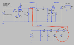
I'm thinking about how to reduce hum into the 6C6 supply grid while preventing the 0C3 from oscillating. If a large cap in parallel to the 0C3 is a problem, what if I split the feeding resistor into two of lesser value, placing a cap between them and leaving the second one in series to the 0C3, as pictured in the attachment?
The large cap in parallel with a gas tube is likely to oscillate.
I'm thinking about how to reduce hum into the 6C6 supply grid while preventing the 0C3 from oscillating. If a large cap in parallel to the 0C3 is a problem, what if I split the feeding resistor into two of lesser value, placing a cap between them and leaving the second one in series to the 0C3, as pictured in the attachment?
Attachments

You really don't want me to use that 0C3 on the supply screen, eh? 🙂
I hadn't thought about taking feedback from the 300B cathode. Interesting idea.
I hadn't thought about taking feedback from the 300B cathode. Interesting idea.
I'm thinking about how to reduce hum into the 6C6 supply grid
Is this actually an issue?
The bigger issue with this design is the gratuitous HF rolloff.
Well it's been an interesting couple of years and I'm finally circling back to finish this project. The original WE91A circuit lived on my breadboard for over 2 years; I loved listening to it nearly every day. It sounded fantastic with the big trapezoidal onkens I made with Lowther PM6A.
Here is a candidate for the final circuit (one channel shown), which closely mirrors the original WE91A with some notable exceptions:
Thanks for looking.
Here is a candidate for the final circuit (one channel shown), which closely mirrors the original WE91A with some notable exceptions:
- It can run 310A or 6C6 as input tube (using switches)
- 300B -- 400Vak/60mA
- 310A -- 200Vak/2.8mA (0.5 watt dissipation)
- 310A cathode bypass cap removed in order to reduce gain for input sensitivity of 1.85V: this amp will have a low gain line preamp in front of it.
- 0C3 on screen grid has 7.7mA going across it -- yes, it's functionally unnecessary: it's my party and I'll be decadent if I want to
- The bootstrap capacitor of the original WE91A is removed for zero feedback (in homage to the `90s Triode Revival)
- Coupling cap is an NOS PIO Sprague Vitamin Q 0.1uF 1000V
- All caps in the power supply are motor run oil caps. I might change the series to 25uF, 50uF, 100uF for increased filtering and bandwidth.
- Rectification will come from a 5Z3 in each channel. PT is 800Vct.
Thanks for looking.
Attachments
Did you ever finish the build and was the above circuit the final one? Also, did you try the cathode feedback circuit from the 300B that PRR recommended?
Hi BHD. Thanks for the interest. I never built the circuit with 0C3 or the cathode feedback. Last year, because of a deal on a pair of 2A3s that I couldn't pass up, I ended up working on SET circuits with that tube (still am), and during that process learned more about how the interaction between the input tube, its plate load resistor, and the output stage limits the high frequency response. Other people in this thread were warning me about the excessive high frequency rolloff of the WE91A, but I didn't understand the mechanics of what they were saying. Someone in the 2A3 thread explained how to calculate it, so I made a function for it an an Excel spreadsheet where I've automated other tube amp calculation procedures.
With 6C6 or 310A on input, and with a 100K plate load resistor, the high frequency rolloff would be very steep (I think around 10-12kHz, if I recall), so I would lower that resistor to at least 75K and probably run the tube with more current to limit slewing on the 300B grid. Also, the 6C6 and 310A grids might not draw enough current for 0C3 to work properly. But again, I never tried it because I changed direction.
I might return to this project but am more interested in other topologies now, such as direct-coupled (breadboarded the Fi X yesterday, it's not bad but not great), interstage transformer coupled, and direct-heated triode input/drivers. If I can find plate chokes with enough inductance, after the 2A3 project is done, then I'll probably start by breadboarding the old Komuro 300B circuit, a 3-stage, all direct-coupled affair, and taking it from there.
Last edited:
Thanks for the quick response, I'm looking into building an amp like yours above with the JJ 2A3-40 and the 57 as the driver tube. The 2.5V filaments on both tubes will hopefully mean less hum, plus the 57 can be found rather cheap. I plan on using damper diodes for the rectifiers. I was hoping that the cathode to grid feedback recommended by PRR would help with the high frequency roll off and I also thought about trying a bit of plate to plate (Schade) feedback as well. I'd be using the amp with a preamp so I'd also likely do away with the cathode bypass cap on the driver tube.
I'm very interested in the Lowther Onkens you built, I'm considering buying the plans from Dave. Did you find that the HF roll off on the amp helped with the Lowther's rising top end?
I'm very interested in the Lowther Onkens you built, I'm considering buying the plans from Dave. Did you find that the HF roll off on the amp helped with the Lowther's rising top end?
Seems like that circuit could be good, but I have no experience with the 57. I've found 2A3 to not need a hum pot in my applications. My Lowthers don't have a terrible rising top end. The PM6A with silver voice coil (what I have) has a much flatter frequency response curve than most other Lowther drivers. I'm running mine without a filter and don't feel the need to modify anything. However, I've never measured the in-room frequency response.
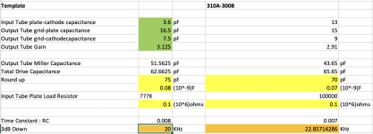
I went back to my spreadsheet and filled out the formulae more fully so that I could easily copy-paste templates into new columns and enter info from the tube datasheets to obtain quick calculations. The attached screenshots show that 310A with a 100K plate load resistor, driving 300B, should be down 3dB at 22.8kHz, which is fine. With a 75K plate load resistor that ends up being 30kHz.
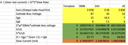
I calculate the minimum slew rate current of this circuit to be 3.7mA. So you'd want at minimum about 4mA of drive current from the input tube into the 300B.
I went back to my spreadsheet and filled out the formulae more fully so that I could easily copy-paste templates into new columns and enter info from the tube datasheets to obtain quick calculations. The attached screenshots show that 310A with a 100K plate load resistor, driving 300B, should be down 3dB at 22.8kHz, which is fine. With a 75K plate load resistor that ends up being 30kHz.
I calculate the minimum slew rate current of this circuit to be 3.7mA. So you'd want at minimum about 4mA of drive current from the input tube into the 300B.
Attachments
The 57 tube is 6C6 with a 2.5V filament, so it should work fine. Thanks for calculating that info.
I entered the values for 6C6 pentode and the HF rolloff is down 3dB at 26kHz with a 300B on output. With 2A3, 6C6 pentode HF rolloff is 3dB down at 24kHz.
- Home
- Amplifiers
- Tubes / Valves
- WE91A 6C6