I sent an email to Audio Research service to ask if there is a switch out there which fits the same footprint. I am not sure they will get back to me with anything useful. Last time I asked something they just sent me a copy of the User Manual. But it does not hurt to try. Not sure how they expected these to measure something on the order of 50mA over time.
got a reply from Audio Research:
"Yes, we would recommend trying to clean it. DeOxit is ok but we use LPS1 here. A small amount usually does the trick and work the pot back and forth 40-50 times through its full rotation to clean as much as possible out of the contacts. If that does not work it will most likely need to be replaced. I cannot share that type of technical information or sell you any parts directly, however."
-----------
I already turned the trim pots back down to min while waiting for DeoxIT in mail. I may still have to look at that axial play on one pot's shaft. p.s. however, D150 is moving down on my priority list as I am likely to finish my LX521 Xover and get those going with Papa's SS amps first.
last update: used deoxIT. 7 out of 8 positions on the bias switches work fine. the handle jumps up and holds steady, it is no longer jumpy like before. However at V14 position it still does not move at all. I swapped the tube to another socket and it is the measurement that is an issue, not the tube.
So this service apparently will not be easy. I may have to take the front panel off and try to measure off the wires on the switch. Finding and soldering in a replacement switch would be a project in itself .
.
So this service apparently will not be easy. I may have to take the front panel off and try to measure off the wires on the switch. Finding and soldering in a replacement switch would be a project in itself
.sorry, just got busy. It is a shame because it was so close to working. I pulled the switch out and took measurements across it. It measured fine but when I reinstalled it the bias in that position again did not work. Then I got a new 5 position switch but the threaded part was not long enough for the thick front plate. Then I got upset for spending so much time and went back to my other projects. But I am probably going to look at it again real soon.
https://www.diyaudio.com/forums/tubes-valves/354104-audio-amateur-2-1984-audio-research-150-a.html#post6195847
https://www.diyaudio.com/forums/tubes-valves/354104-audio-amateur-2-1984-audio-research-150-a.html#post6195847
finally got to take another look at V14 not biasing.
at this point it is not the switch issue. I took both switches out and cleaned them out with Deoxit. I also soldered wires and brought them out for V14 bias measuring position and used digital multimeter to measure voltage across the 1ohm resistor. No voltage. So I pulled out all even numbered OP tubes and measured voltages from pins 3, 4 and 5 relative to 8. For V16, V18 and V20 they all measured 603V, 371V and -45V respectively. On V14 base [pins 3 and 5 Ok but pin 4 0V. Checked resistance from pin 4 to pin 4 and V16 to V18 ~20 ohm but V14 to V16 OLoad. V14 to V20 the same. So it looks like R42 3W/10Ohm by V14 base must be toasted.
So all tubes and the mid pcb will have to be dismounted again. I cannot believe I missed that before when I was changing resistors by V19 which initially threw the fireworks. And I thought I had checked all these voltages on all bases. However when I swapped V14 and V16 before the tube was biasing in the V16 socket so the tube should be Ok.
Anyways I know what the next step is and will get to it probably within a week or so. I guess I should be happy that the switches may stay because finding a 5 position switch with the thread long enough for the 1/4inch thick face plate seemed impossible. So that should be a positive I guess...
at this point it is not the switch issue. I took both switches out and cleaned them out with Deoxit. I also soldered wires and brought them out for V14 bias measuring position and used digital multimeter to measure voltage across the 1ohm resistor. No voltage. So I pulled out all even numbered OP tubes and measured voltages from pins 3, 4 and 5 relative to 8. For V16, V18 and V20 they all measured 603V, 371V and -45V respectively. On V14 base [pins 3 and 5 Ok but pin 4 0V. Checked resistance from pin 4 to pin 4 and V16 to V18 ~20 ohm but V14 to V16 OLoad. V14 to V20 the same. So it looks like R42 3W/10Ohm by V14 base must be toasted.
So all tubes and the mid pcb will have to be dismounted again
. I cannot believe I missed that before when I was changing resistors by V19 which initially threw the fireworks. And I thought I had checked all these voltages on all bases. However when I swapped V14 and V16 before the tube was biasing in the V16 socket so the tube should be Ok.Anyways I know what the next step is and will get to it probably within a week or so. I guess I should be happy that the switches may stay because finding a 5 position switch with the thread long enough for the 1/4inch thick face plate seemed impossible. So that should be a positive I guess...
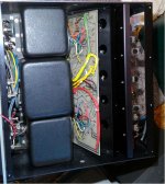
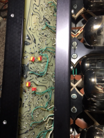
mid board exposed again. Yep, the resistor was faulty. I soldered a replacement in. What bothers me is that the resistor showed no signs of damage by the looks of it. So I wonder if they could be going bad just from age? I left the amp open to think if I should replace some more.
The problem is that the bunch of wires at the bottom make half soldering points hard to access so I am afraid of incurring some damage if I start tempering more than necessary.
The problem is that the bunch of wires at the bottom make half soldering points hard to access so I am afraid of incurring some damage if I start tempering more than necessary.
Attachments
Finally getting back to it. I had an accident in early August and took three months to recover. Another month or two to get caught up on work. Well I hope to use the Covid restricted holiday season to get caught up on the D150 prep.
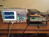
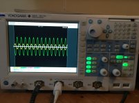
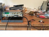
I loaded the output with an 8ohm resistor and took a (half) measurement from the grounded 4 ohm tap with input around 1kHz. Checked both channels and it looks Ok. So the amp seems functional now. All OS tubes biased to 55mA on the dot and the voltage gain checks out.
Now I am getting ready to convert the input to balanced so I can try it in my intended system with Aleph P v1.7 preamp. I guess the cleanest would be to take the jumper out for 350V rail to the invertor tubes but I do not feel like pulling again all the input tubes out and the whole board on the back; so I am thinking of just cutting on one side the few components that need to be lifted like R5, R6, C1. Then bringing the + balanced lead to after C3, - lead to R7, and just adding a pair of 39pF RF filter caps, one on each + and - to ground. So no DC cap and no pot. Preamp has 3x10uF Wima caps on output so Dc should not be a concern.
Here is the picture of the measurement:
Attachments
Although not the same amp, there is some info scattered in this thread about using balanced inputs, and the D150, also Dave (author) is very familiar with the D150 I believe, and may be of some help if you can use it.
Parts and Pieces: A True ARC Mystery | Audiokarma Home Audio Stereo Discussion Forums
Parts and Pieces: A True ARC Mystery | Audiokarma Home Audio Stereo Discussion Forums
Thanks. I will check it out. So far I am going by info received in this thread mainly from Rayma, who kind of runs a sanity check on what I am doing and seems to have direct D150 experience.
In any case I will try to implement balanced input in a temp (non pretty) kind of setup with pigtails with XLR connectors so it can easily be put back to its original condition. The plan is still to try the amp for a while, just for curiosity's sake, and then probably sell it to fund another speaker project.
In any case I will try to implement balanced input in a temp (non pretty) kind of setup with pigtails with XLR connectors so it can easily be put back to its original condition. The plan is still to try the amp for a while, just for curiosity's sake, and then probably sell it to fund another speaker project.
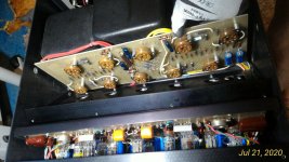
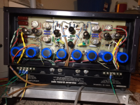
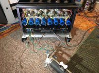
Installed pig tails for the balanced inputs. Of course in order to do a decent job I ended up taking the rear pcb pff; so I soldered the recommended smaller RF filter caps (47pF Wimas) under the board (picture attached).
The pig tails are still missing the XLR connectors since I want to test the amp before soldering them on. Currently they bend pretty sharply to make it out under the amp. I was thinking of removing RCA connectors and using those holes to bring them out, but RCAs are soldered to the pots etc. so it takes more tear up than just unscrewing them. So I left it alone for the time being until I decide the amp future for the longer term.
You can see the two balanced input cables in the middle (the "V") and the three leads out of each connecting to the board. I drilled a few holes for the smallest zip ties to fasten the leads if they get tugged on. I removed the DC film caps and left the other disconnected film cap and a resistor just lifted off the board for the time being.
Attachments
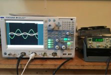
Tested both channels (one at a time) with balanced inputs. Used a transformer to get from unbalanced to balanced on the signal generator output. Swept frequency up to 20KHz and all checks out. Did not sweep amplitude a whole lot not to test my resistor load too much. Anyways, that was yesterday. Yesterday was a good day.
Attachments
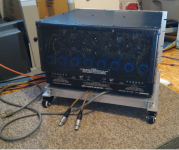
Today, in almost festive mood I screwed on the covers. I left the bottom cover off in case I decide to bring the pigtails out through the RCA connector holes later on. Hooked it all up into my audio chain. Turned it on, big time hum like a ground loop in the right speaker. On turn off a big pop in the same speaker. On the right channel plate fuse light on and then the screen fuse light comes on as well. 
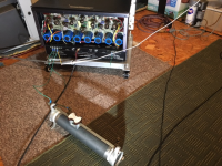
Wheeled the amp back to the shop. Laid down a hammer next to it in case I decide to end the misery. Put my tried and true Burning Amps back in and confirmed that all other equipment is still OK.
I have no freaking idea how I could get the ground loop. I was already aware that the ground on my preamp is lifted off the earth with a 10 Ohm thermistor while D150 amp (signal) ground is straight on earth. But the cable shields are only connected to D150 ground in one spot right on the back pcb.
The system is bi-amped with another identical preamp driving ICEpower amps for the sealed bass units; so maybe I have to give it some more thought . I think I will wait for a friend of mine who is more knowledgeable before getting back to it. I am a little fed up with the unit right now. I am already $1k into it with all the refurb, not to mention my hours which could be better spent listening to my existing audio equipment than tinkering with this glass elephant.
Wheeled the amp back to the shop. Laid down a hammer next to it in case I decide to end the misery. Put my tried and true Burning Amps back in and confirmed that all other equipment is still OK
.I have no freaking idea how I could get the ground loop. I was already aware that the ground on my preamp is lifted off the earth with a 10 Ohm thermistor while D150 amp (signal) ground is straight on earth. But the cable shields are only connected to D150 ground in one spot right on the back pcb
. The system is bi-amped with another identical preamp driving ICEpower amps for the sealed bass units; so maybe I have to give it some more thought . I think I will wait for a friend of mine who is more knowledgeable before getting back to it. I am a little fed up with the unit right now. I am already $1k into it with all the refurb, not to mention my hours which could be better spent listening to my existing audio equipment than tinkering with this glass elephant.
Attachments
Last edited:
I am also pretty sure this was not a ground loop, it only sounded like one. Maybe something to do with the balanced mod? Maybe it is not as simple as it was suggested here? How could it test fine on the scope and then throw a fit like this when connected into the audio chain?
All I could bring myself to do today was to take the covers off. Visually inspect it. Nothing stands out. Confirmed that the plate and screen fuses were blown. These were new KLM-1 and KLM-2 which I had put in. The amp came with an FNM 2-1/2 for the plate fuse (which suggests they blew it before), so I put in a fast acting KLM-2 as specified. Line fuses are still Ok.
If I want the exact KLM fuses I will have to order them. I am thinking: pull (again) all output stage tubes out, and start from the beginning. Measure across the bases. Then replace fuses and power up the amp. See if it holds up. Check voltage on the rectifier bases then plug those tubes in (these are replacement Sovteks I got). Add rectifier tubes and check rectified voltage on all bases. etc. If there is something wrong with the input board on the back, all I can think of right now is to restore connections for the unbalanced inputs.
I am open for any suggestions as this will take some time now.
Ok, this seems to have been my doing .That happens when one does the work with large gaps in between. You end up thinking "you kind of know" and do not check back on the thread. I left both V1 and V2 in their sockets and on top of that forgot to lift the R6, so clearly the minus from the balanced signal got some loop going and something got toasted. In hindsight I cannot believe it, but testing with a small input amplitude and output looking good on the scope threw me off to think that everything was fine.
I corrected the balanced mod now. The output stage seems Ok. After checking across the bases I re-plugged all big tubes, put the plate and screen fuses in and rebiased the tubes without blowing any fuses. I even loaded the amp output and fed the balance signal in but this time the scope shows nothing at the output;, so clearly something is toasted.
Any idea what to check for first? I hope it is something that is accessible on the back board. The small tubes in the input stage are all glowing but that is as far as I got so far. I will probably pull them out and check that they are getting the proper voltage, and start looking into each resistor I guess.
.That happens when one does the work with large gaps in between. You end up thinking "you kind of know" and do not check back on the thread. I left both V1 and V2 in their sockets and on top of that forgot to lift the R6, so clearly the minus from the balanced signal got some loop going and something got toasted. In hindsight I cannot believe it, but testing with a small input amplitude and output looking good on the scope threw me off to think that everything was fine.I corrected the balanced mod now. The output stage seems Ok. After checking across the bases I re-plugged all big tubes, put the plate and screen fuses in and rebiased the tubes without blowing any fuses. I even loaded the amp output and fed the balance signal in but this time the scope shows nothing at the output;, so clearly something is toasted.
Any idea what to check for first? I hope it is something that is accessible on the back board. The small tubes in the input stage are all glowing but that is as far as I got so far. I will probably pull them out and check that they are getting the proper voltage, and start looking into each resistor I guess.
- Status
- This old topic is closed. If you want to reopen this topic, contact a moderator using the "Report Post" button.
- Home
- Amplifiers
- Tubes / Valves
- D150 monster amp and funny tooobz