Use the attached schematic instead. There are some unlabeled parts in the previous one. I'll have a full write-up of the project in a couple days, too.
I intend to try the folded cascode in a phono stage as well. Really neat circuit and now I've got a bunch of boards to use up!
I intend to try the folded cascode in a phono stage as well. Really neat circuit and now I've got a bunch of boards to use up!
Attachments
Sorry for resurrecting this thread... I came across this stuff while researching an LTP input stage using cascodes while thinking about options to drive some 6C33C tubes (4 output tubes in a circlotron OTL). I believe the cascode stage developed in this thread might be a good choice.
- Will this drive the paralleled big fat grids of the 6C33C through a DC blocking capacitor? Or should I consider something like adding a PowerDrive source follower?
- Are there any boards available to build this shunt-cascode LTP? Since my recent adventures with an Aleph-J on protoboards I am back to either proper PCBs or dead-bug style (which wouldn't work well for this project).
I made some PCBs for a single shunt cascode and just doubled them up over a CCS to work as a LTP. Rod's boards and kit would work just as well, I'm sure.
As far as driving bigger grids, I've considered trying another design with a direct coupled mosfet follower. With a negative rail, you could conceivably direct couple all the way through. Haven't tried it though, just a pipe dream ATM.
As far as driving bigger grids, I've considered trying another design with a direct coupled mosfet follower. With a negative rail, you could conceivably direct couple all the way through. Haven't tried it though, just a pipe dream ATM.
I made some PCBs for a single shunt cascode and just doubled them up over a CCS to work as a LTP. Rod's boards and kit would work just as well, I'm sure.
Do you have some left over boards?
As far as driving bigger grids, I've considered trying another design with a direct coupled mosfet follower. With a negative rail, you could conceivably direct couple all the way through. Haven't tried it though, just a pipe dream ATM.
Interesting! Is there anything you can share?
Unfortunately not that I can send out immediately with the USA under quarantine. If you aren't in a rush though, let me know.
I didn't really get much further than the schematic in post #2 as far as a direct coupled mosfet driver. With the kind of voltage swing and negative bias needed for big triodes, a to92 may not allow for enough dissipation. There is a lot of balancing voltage supplies and dissipation
I mean to come back to the idea once I find the right big triode")
I didn't really get much further than the schematic in post #2 as far as a direct coupled mosfet driver. With the kind of voltage swing and negative bias needed for big triodes, a to92 may not allow for enough dissipation. There is a lot of balancing voltage supplies and dissipation
I mean to come back to the idea once I find the right big triode
Hi
Interesting stuff!
The schematic in post-58 is missing voltage-sharing resistors across the series-connected power supply caps - that's a crap shoot! Sharing depends on leakage currents being equal.
I have a basic Q:
Isn't there a risk of all the solid-state stuff "interfering" with the tube sound? I know hybrids give lower THD than pure tube and I've used them several times, but isn't the point of choosing tubes in the first place entirely because they have imperfections thought to be musical?
Just wondering
Doing a PP version of my Shunt Cascode power-valve driver is attractive.
My latest version of (SE) Shunt Cascode PCB has advanced quite a way, and has means to control the dc drift. And a new fully-discrete regulator for the cascode voltage (the performance of the base-regulator is a major influence on the sound, and the measurements of the Shunt Cascode stage). It also has a carefully designed grid-driving FET source follower, to give 100kHz bandwidth for the whole stage.
Send me some PM, if you are interested in news of it.
Isn't there a risk of all the solid-state stuff "interfering" with the tube sound? I know hybrids give lower THD than pure tube and I've used them several times, but isn't the point of choosing tubes in the first place entirely because they have imperfections thought to be musical?
Just wondering
The transistor in the Shunt Cascode stage is designed to give a different way to exploit the excellent open-loop distortion of a triode.
Among other things, it allows a single triode to give gains well-above µ (> x200 is not difficult). This in turn makes it possible to build single-stage power-valve drivers - with big swings for 300Bs and more - that run directly from a DAC.
Yes, it measures better than 2-stages of triodes, and it has much lower input-capacitance than single high-µ triode stages - but these things make it sound better, IME.
You'll just have to try it!
A great idea to implement a differential stage with a folded cascode. Surely will perform perfectly well, and should sound as good as it sounds the single ended.
I concur and will highly recommend Rod’s board. I implemented a phono stage 50dB gain with extremely low distortion. The stability of Rod’s reference voltage and tiny compact PCB design is a plus. No point in building your own PCB when this kit is readily available.
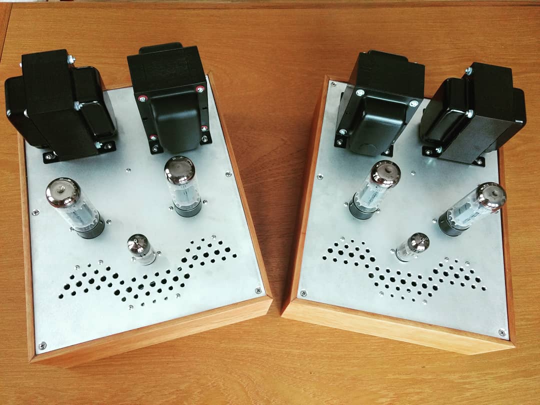
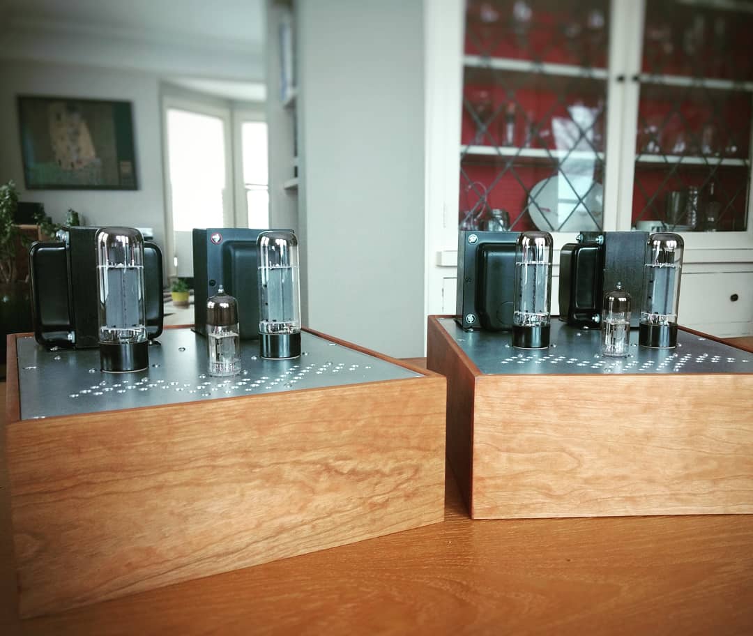
Here are some of my experiments with DHTs and at the bottom of the blog entry there is a snapshot of the phono stage:
DHT Folded Cascode Experiments – Bartola(R) Valves
I concur and will highly recommend Rod’s board. I implemented a phono stage 50dB gain with extremely low distortion. The stability of Rod’s reference voltage and tiny compact PCB design is a plus. No point in building your own PCB when this kit is readily available.
Here are some of my experiments with DHTs and at the bottom of the blog entry there is a snapshot of the phono stage:
DHT Folded Cascode Experiments – Bartola(R) Valves
A great idea to implement a differential stage with a folded cascode. .. Here are some of my experiments with DHTs and at the bottom of the blog entry there is a snapshot of the phono stage:
DHT Folded Cascode Experiments – Bartola(R) Valves
I quickly skimmed through your post(s). Good stuff! Looking at the output / driving part linking to the grid of the power tube, I see that you included a MOSFET source follower in some of your circuits, which then drives the grid of the output tube through a coupling capacitor. Why didn't you arrange this in the typical "PowerDrive" sequence, with the capacitor first and then the MOSFET source follower directly on the grid of the power tube?
Giving it a bit more thought after this got resurrected, I'd change the approach from post #2 to something like this:
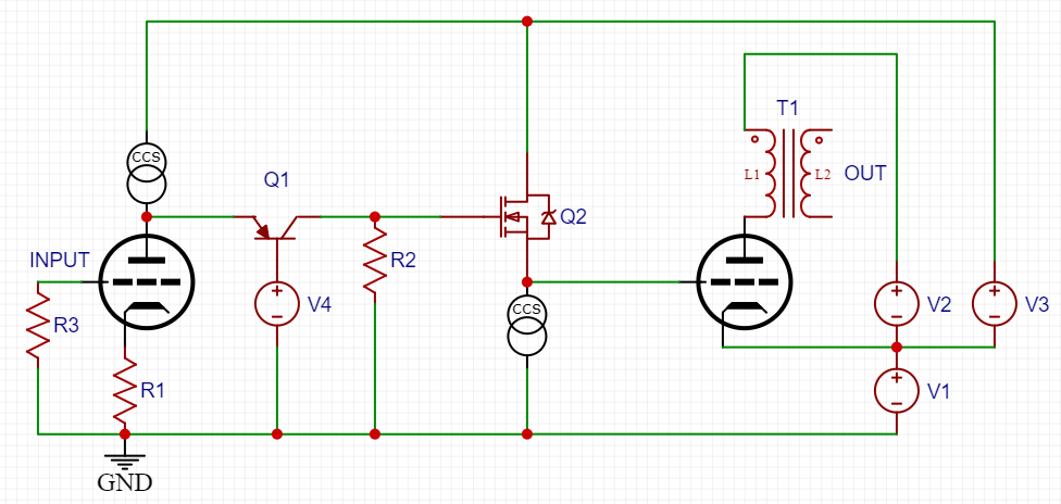
It doesn't really save on the number of supplies, but it keeps more of the input referenced to ground (simpler building, I think). V1 would end up being about half the intended swing into the output tube grid plus the bias voltage.
I built my cascodes with 300V B+ and about 75V idle at the transistor collector (150V ptp swing). So for something like a 2A3, I'd be looking to make V1 around 120V, V3 around 180V, and V2 around 250V.
Should also be plenty capable of A2 operation this way.
- Status
- This old topic is closed. If you want to reopen this topic, contact a moderator using the "Report Post" button.
- Home
- Amplifiers
- Tubes / Valves
- Folded/shunt cascode differential question