Sorry for taking another short detour off topic—I think we really should separate opinions about people from that of governments. What the CCP does in power over the last decades does not represent the people or culture over centuries, much as the CCP like to portray they do. Same as generalizing about all Americans based on policies of the party in power.
Back to tube amps…
Back to tube amps…
Last edited:
Most of it is over my head but thanks for the interesting and very detailed analysis. I would like to point out a couple of things.Since my thoughts on 61J preamp will not fit into one post I have compiled a document,
It comprises $1 modification path in both Cathode follower (reaching THD: 0.009528%) and Common Cathode (reaching THD: 0.196589%) setups.
I have build both and they are working smoothly.
If you find my thoughts useful please consider buying me a beer for the dedicated free time in the span of 3 months, specially if you want to use my design for commercial purposes (yes, I mean you Chinese people too)
First, the plate curves shown in the document are for the tube in its normal pentode mode and all the preamps that use them run them in triode. The "specifications" link in the text brings up the Chinese data sheet and it does show triode curves. Here they are from the much clearer Raytheon data sheet.
I'm not sure how much the use of the wrong curves might affect your analysis.
Also, I had earlier run across some estimates of the plate resistance (Ra) of the tube in triode and your calculations confirm that it is ~4k. But then you say that the plate load resistor (R15), which is 4.7k is appropriately sized.
I've always been told that the "rule of thumb" is that the plate load resistor should be a minimum of 3x to 5x the plate resistance of the tube. Yet, you reduce it further to 2.2k, apparently in order to reduce the gain.
My only interest is that I breadboarded the 6AK5 a while back. I tried them at the stock operating points found in this schematic, which are also the same as the popular FX Tube-01 version uses. (The FX uses a different power supply section, however. It's powered from a DC wall wart whereas this version uses an AC input.) I also tried them at the higher voltages recommended in the data sheets. I much preferred other tubes, though I did hear a significant improvement when running them at "normal" voltages. I was using 22k plate load resistors in that version.
Many people who use these preamps complain about too much gain, which manifests itself in having very little range of adjustment on the volume pot. So, while reducing the gain might be desirable, I'm not sure if reducing the plate load is the best method.
I'm not very technically astute, though, so maybe others who are more knowledgeable will comment. Are there other methods that might be better?
I figure if you need less gain it's better to start with a lower gain tube, which is what I did when I eventually built a preamp after all my breadboarding. After all, most amps can produce full power output without any gain at all, although many benefit from a bit of gain in terms of dynamics and "tube flavor".
Thank you for your time reading the document FlaCharlie.
"Appropriately sized" means that the current is within specification and the voltage across tube is approximately half of maximum., which allows swing in both directions without clipping.
Regarding rules of thumb, they guide you to typical results and I find them handy too,
I know that the tube is pushed out of its typical operation, nevertheless "extreme" result calls for "extreme" measures.")
"Appropriately sized" means that the current is within specification and the voltage across tube is approximately half of maximum., which allows swing in both directions without clipping.
Regarding rules of thumb, they guide you to typical results and I find them handy too,
I know that the tube is pushed out of its typical operation, nevertheless "extreme" result calls for "extreme" measures.
That may be true. But extreme measures are only necessary if you start with a design that's compromised.I know that the tube is pushed out of its typical operation, nevertheless "extreme" result calls for "extreme" measures.
That said, I'm not very technically oriented and I'm certainly not always a stickler for following "the rules" or striving for engineering perfection.
But if you're capable of building something yourself there are far better choices. Why start with something that requires "extreme measures"?
If you're building point to point you can choose a more appropriate tube that has lower gain, which is what I did. If you're limited to building something that's available as a circuit board based kit there are other designs that are well engineered and proven such as the kits, including zero gain buffers, sold by John Broskie at Glassware.
Most of the people who use this design are not into DIY, they just want something cheap that adds "tube flavor" to their systems, which are mostly SS and Class D. So they buy one of the popular FX preamps or one of their many cousins that use the same tubes. For someone who owns one of those your suggestions might be worthwhile. But as a DIYer, I'd just avoid these boards.
Perhaps others will comment on the effects of using a plate load resistor that's roughly half the value of the tube's plate resistance rather than the 3x to 5x "rule of thumb".
Sorry for the generalization, but my understanding is that every design is a set of compromises.
Either you compromise on size, cost, distortion, consumption, tube selection e.t.c.
Every design can be improved in one way or the other.
I see this particular design as an entry level to the tube world.
It is cheap enough to try it out, while you can experience the magic of the tubes i.e. soft sound & glow.
But there are annoying artifacts with the design that might act as blockers to continue exploring the tube world.
My first post is an attempt to make it usable, while retaining the cost, with simple enough modifications.
It is up to everyone to choose what fits their purposes.
Sure, everything has it's compromises and limitations. But the limitations here have certainly not acted as blockers to those wanting to explore the tube world. This basic design has actually acted as an introduction to the tube world for thousands of people who had never tried tubes before.every design is a set of compromises . . . I see this particular design as an entry level to the tube world. It is cheap enough to try it out, while you can experience the magic of the tubes i.e. soft sound & glow. But there are annoying artifacts with the design that might act as blockers to continue exploring the tube world. My first post is an attempt to make it usable, while retaining the cost, with simple enough modifications. It is up to everyone to choose what fits their purposes.
Not as a DIY project using these little boards, but in the form of the inexpensive FX preamps and their cousins which have become extremely popular. There is a massive, long running, thread about the FX over on the Audio Karma board.
https://www.audiokarma.org/forums/index.php?threads/fx-audio-6j1-tube-preamp-a-31-wonder.848535/
For 99% of the people who want to explore tubes a DIY build from scratch, or even from one of these little boards, is of no interest. They just buy something that's plug and play that has tubes. Some of the posters on the AK thread are into modding their FXs. They'll spend lots of time and money rolling tubes, replacing caps and, on the newer versions, rolling op amps.
I've suggested, on many occasions, that if FX owners want to use these 6AK5 family tubes and get better sound that they should try building something that at least runs them at normal voltages, which I found to be a big improvement when I breadboarded them. So far nobody has shown any interest.
Your research into this design might be of interest to them if, instead of starting with a DIY board, you picked up one the FXs and posted details of how to mod it, including pics, over at AK. I'm sure there are a thousand or more FX owners for every one of these little boards that has been sold.
Since they are new to tubes, most of the people who mod theirs don't have any clue as to how the circuit works or what the effect of changing a particular part might have. Some of them follow the advice found on YouTube videos which are posted by people who are totally clueless.
Like the guy who, when asked about the power supply, said "there is no power supply"! His video describes how he replaced two 10uf 25v electrolytics with film caps. OK. But instead of using a single $3 film cap of the same value, he soldered together two giant blocks of ten 400v 1uf caps, that cost about $80 which are then connected to the board with long wires.
Another website that the modders sometimes refer to was posted by someone who claims to be an EE but, in addition to other issues, his "testing methods" are totally flawed.
So, if you want to present your experience to a much wider audience, reach out to the FX owners. Most of the DIYers on this board probably have little interest in these preamp kits since their knowledge is much more advanced.
If you have the interest and ability to build something why bother starting with this board and these type of tubes?
The most obvious compromise that stands out to me is purely practical and based on the discussion of the FX on AK. A recurring complaint seems be that the volume control has very little range of adjustment. This can, in large part, be traced back to the use of a tube that has too much gain. Such complaints are not limited to these tubes or this design. I hear similar complaints about other, sometimes quite expensive, preamps that use tubes with too much gain.
The preamp I built uses exactly the same circuit design as the FX and these little boards but I used a tube with a mu of 5, so there is no issue with excessive gain and, to my ears, it sounds much better than the tubes used in this design. YMMV, of course, but I listened to about a dozen different types and the 6AK5 was near the bottom, even when run at normal voltage.
From a technical perspective . . . I rarely draw load lines so I have to re-educate myself whenever I do. But when I was breadboarding the 6AK5 at the stock FX voltages I drew a load line and it was way down in the bottom left corner of the triode plate curves, which I posted above.
You might want to try it yourself since you apparently used the wrong curves in your analysis.
I was actually surprised that the sound was as good as it was given the horrendous load line. Those who bought an FX are stuck with using these tubes but if you're building something from scratch there are far better choices.
Maybe it is wrong thread, but this is a thread where I see the board I have played with and where I wanted to contribute in return.
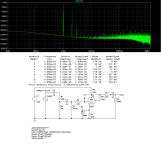
I took the liberty and looked at design from your post at other forum. I have run it through the simulation. Here are the results
If members at other forum can provide schematics for Audio FX board, I may have a look, but I will not buy it just to play with it.
Looking at the board as advertized, it takes different means of voltage boosting, there seems to be some sort of power source
filtering with low pass filters, I believe it will use same common cathode design.
Attachments
You're posting in the correct thread here on DIY, although there may be others on here too. I just wanted to let you know that, if you want the results of your research to benefit more people, that there are many many more FX owners out there than people who have bought and built one of these little boards.Maybe it is wrong thread, but this is a thread where I see the board I have played with and where I wanted to contribute in return.
I took the liberty and looked at design from your post at other forum. I have run it through the simulation. Here are the results
If members at other forum can provide schematics for Audio FX board, I may have a look, but I will not buy it just to play with it.
Looking at the board as advertized, it takes different means of voltage boosting, there seems to be some sort of power source
filtering with low pass filters, I believe it will use same common cathode design.
As for similarities, as far as I know the original FX Tube-01 and all subsequent versions use the same basic audio circuit as the board you have and run the tube at the same voltages / operating point. The power supply section is different in that it uses a wall wart that supplies DC and the board you have has an AC input. But the resulting voltage is the same. Beyond that, I don't know as I don't own an FX and I'm totally uninformed about these types of power supplies.
As for other FX versions, the Tube-01J is a version that's made in Japan but the only difference is that it has a switch that reduces the output by (as I recall) 6db. The more recent Tube-03 adds tone controls and has two op amps that control (not sure how they work) them as well as the volume control. Owners like to experiment with rolling a variety of op amps and some remove the op amps, which bypasses the tone controls and/or volume control. There may be other versions now too. They are hugely popular so I think the Chinese have combined the basic preamp circuit with various other features like a built in DAC or headphone amp.
So, again, if you want your efforts to reach a much larger audience, there are many FX owners who are into modding but seem to have no interest in DIY, either from scratch or from a kit like you have.
The difference in interest between the FX and these little boards is quite clear. This thread, which was started in July 2017, has less than 250 posts. The main thread on the FX over at AK, which was started 17 months later in December 2018, has over 4500 posts and has been viewed over 400,000 times.
I had no interest in actually using the 6AK5 in the preamp I built but I was intrigued by all the interest in the FX. So since I was in the process of breadboarding other tubes (all of which had a mu of less than 10) I tried the 6AK5 at the FX op points and at higher voltage and discussed the results in the AK thread. The schematic I posted there just runs the tube at more normal voltages and I thought it sounded much better like that than it did at the stock FX voltages.
I have no experience with Spice sims or whatever you're using and I have no idea how to interpret the results. I'm pretty much a copy and paste builder and I make decisions almost exclusively based on what sounds best to me. As I said, of the dozen tubes I breadboarded in the same basic circuit, the 6AK5 was near the bottom to my ears.
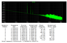
In introduction to tube design on page 71, one can see a frequency response that we strive for. The plateau (flat region) shall be at least in human audible range and shall be as flat as possible. Design from your post at other forum resembles more a low pass filter than amplifier response that one longs for, it might be correct though, depending on source and target circuits. Since there is the attenuation, 2nd-10th harmonic frequencies do not contribute to THD as with flat response, thus the value might be not comparable.
With regards to “the wrong curves might affect your analysis”, LT Spice model by Robert McLean has all the curves modeled as precisely as possible, thus need for load lines and other calculations as shown in introduction can be saved. The quiescent point I took from 6J1 specification places me at the start point for modification.
I rather use Spice modeling in order to save time in breadboarding various variants drawn by other designers to verify the plausibility of their design.
Ad "if you want your efforts to reach a much larger audience", you may cross-reference this thread since you are regular at other forum too
My understanding is that if you search for 6J1 you will land here sooner or later
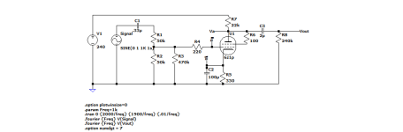
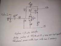
I have tried to correct FlaCharlie design in Common Cathode setup and created Cathode follower.
The potentiometer is set for 0dB in schematics for the calculations. I have done no breadboarding nor smoke testing.
I hope someone will find it useful
The potentiometer is set for 0dB in schematics for the calculations. I have done no breadboarding nor smoke testing.
I hope someone will find it useful
Attachments
As you have suspected very low ~0.3mA.
Chosen resistor (R7-Common Cathode) is used as R5 Cathode follower.
I took R7 as Charlie's design decision, I have tried to accommodate rest of the circuit. to run with the value.
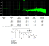
I was trying to show that for any operational point one can have flatter frequency response.
Chosen resistor (R7-Common Cathode) is used as R5 Cathode follower.
I took R7 as Charlie's design decision, I have tried to accommodate rest of the circuit. to run with the value.
I was trying to show that for any operational point one can have flatter frequency response.
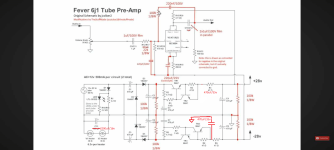
Sorry to resurrect this thread again. But it seems the logical place to put this mostly debugged schematic for modification by TheStuffMade on youtube that drops the output impedance of this preamp from 5kohm to 1.2kohm, limits the upper frequency response from 500khz to 100khz, and pretty well fixes the low end response roll-off issue on power amps with low input impedance. I also added in the most effective hum removal for me. Going to go through acamus' pdf and maybe tinker some more with it. Will probably make a schematic with what seems to be the most effective all around set of mods for this preamp soon. TheStuffMade thoroughly tested his modified pre against a far, FAR more expensive tube pre, and the only place it tested worse was noise floor i believe, but he didn't even attempt hum removal mods for the noise.
I definitely disagree with FlaCharlie. I was quite discouraged by his posts, glad i chose to disregard them. For the money i have into this thing, the performance is honestly pretty ridiculous and it was very much worth buying and modifying. Is also apparently what got me into the diy side of amplifiers and i enjoyed the hell out of trying to figure out how to improve this thing's performance and i've learned a lot more in the process then i expected to..
I definitely disagree with FlaCharlie. I was quite discouraged by his posts, glad i chose to disregard them. For the money i have into this thing, the performance is honestly pretty ridiculous and it was very much worth buying and modifying. Is also apparently what got me into the diy side of amplifiers and i enjoyed the hell out of trying to figure out how to improve this thing's performance and i've learned a lot more in the process then i expected to..
Attachments
Last edited:
Also meant to post a switch mod that's a little bit cleaner if you're not using a wall wart style transformer for this preamp.
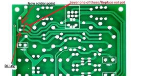
If you solder a jumper between the inner pin of D1 and one of the empty holes near by (pictured), you can just put a switch on the 12v line in from the transformer. And take a pocket knife and just scrape through one of the 2 tracers heading out between the tube pins if you dont want to replace the Pot. It's the same mod, but a much cleaner looking version of it. You can also just unsolder the volume pot, and replace it with an un-switched 2ch 50k potentiometer. If you do this go a50k, not B, you'll have a more usable sweep. That's what i did. Single jumper, replace volume pot. Switch on 12v line in. Looks like it was meant to be this way.
Especially if you're using a little 12v transformer like i am i would recommend this version of the switch mod. Less effort, looks cleaner, same result.
Pictured are the two points that need to be jumped.
It's currently the best performing preamp i have, while also being the most inexpensive by a pretty good margin. It was definitely the most fun to tinker with. My first point 2 point build will likely be the debugged schematic of this preamp because of how familiar i am with the circuit now, how simple it is, and how well it preforms in the end. Plus i got to help in getting this circuit to this point.
I also have no problems if Joe China wants to copy the schematic and release new version. I have no problems at all personally, with this kind of performance being accessible for this kind of money. If that happens ill probably buy one. Honestly. My fosi P1 preamp has more noise, and less output both, then the last schematic circuit i posted, fwiw to someone who cares.
Attachments
Last edited:
I obviously don't have a way to test my preamp. But to my ears, on my setups, this is the absolute best sounding arrangement of this circuit i've been able to come up with. My ears struggle to find fault in what they're getting from this arrangement unless im just blasting it's front end with too much signal.
Sorry for multi-posting. Leaving for future broke, curious nerds that work for a living and can't really afford anything class A pre-built from a typical hi-fi brand and enjoy tinkering and learning stuff.
Personally, I usually skip to the conclusion of a thread like this before reading back. Very worth tinkering with. Total investment was like $14 including new wima's and some old components from a retired pc power supply. Hell, i have spare parts for it without buying anything and so do many. The cost/performance ratio is off the scale.
Attachments
If you got a PC and a decent sound card, then you can measure your pre-amp performance: https://www.diyaudio.com/community/threads/how-to-distortion-measurements-with-rew.338511/I obviously don't have a way to test my preamp.
The sound card can be used as both a signal generator and to measure the output signal.
Only a small pile of em from the last 10 or so yearsIf you got a PC and a decent sound card, then you can measure your pre-amp performance: https://www.diyaudio.com/community/threads/how-to-distortion-measurements-with-rew.338511/
The sound card can be used as both a signal generator and to measure the output signal.
- Home
- Amplifiers
- Tubes / Valves
- 6J1 China preamp thoughts