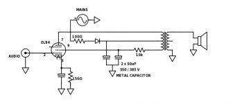
And what wattage is 100k resistor that goes from tube pin 2 to gnd?Oh and whats the value of first capacitor after the rectifier, 82uF, 52uF?
Poslano z mojega S50 z uporabo Tapatalk
Poslano z mojega S50 z uporabo Tapatalk
Ok thanks1/2W is fine. 1W looks better 🙂
Sent from my LG-D801 using Tapatalk
Poslano z mojega S50 z uporabo Tapatalk
Your schematic should work. All tube amp resistors are 1w unless otherwise specified. This is the default for point-to-point wiring, because 1W resistors are rated 200v and are sturdier. If you ever try to use 1/4 or 1/2 watt resistors on point to point wiring, you will break a lot of them. The chinese kit had 2w resistors only, just in case. The first smoothing capacitor is rated 82 uF, you may fit anything between 47 and 220uF. If the capacitor is too big, the power transformer will buzz a little and get hot. The first smoothing capacitor should be at least average quality; cheap/old capacitors will get hot and fail after few months/year. B+ is the conventional symbol for the positive high voltage supply. This has been carried on from the early radio days, when all radios were battery powered. On the original schematic, B is connected to the preamp tube power supply. To identify the primary winding terminals of the output transformer, you should use the ohmeter. The resistence between the center tap (pin 9 of the tube socket) and the plate tap (pin 7) is lower than the resistence between the center tap and the b+ supply. On small EL84 "champ style" guitar transformers about the same size of yours, the resistence between center (grid) and power supply is around 300-340 ohm and between center and plate (anode) is 200-250; total winding resistence is about 600 ohm. An alternate arrangement that was common on vintage parts is the "hum reduction" winding. If you measure a very low resistence between the center tap and one of the other wires, your transformer is actually a common simple primary type and you can disregard the extra tap: connect the tube as triode. Since you have the original circuit, you may check the connections to the tube socket.
Ok, thank you for info. I will build a circuit and wait for isolating transformer.Your schematic should work. All tube amp resistors are 1w unless otherwise specified. This is the default for point-to-point wiring, because 1W resistors are rated 200v and are sturdier. If you ever try to use 1/4 or 1/2 watt resistors on point to point wiring, you will break a lot of them. The chinese kit had 2w resistors only, just in case. The first smoothing capacitor is rated 82 uF, you may fit anything between 47 and 220uF. If the capacitor is too big, the power transformer will buzz a little and get hot. The first smoothing capacitor should be at least average quality; cheap/old capacitors will get hot and fail after few months/year. B+ is the conventional symbol for the positive high voltage supply. This has been carried on from the early radio days, when all radios were battery powered. On the original schematic, B is connected to the preamp tube power supply. To identify the primary winding terminals of the output transformer, you should use the ohmeter. The resistence between the center tap (pin 9 of the tube socket) and the plate tap (pin 7) is lower than the resistence between the center tap and the b+ supply. On small EL84 "champ style" guitar transformers about the same size of yours, the resistence between center (grid) and power supply is around 300-340 ohm and between center and plate (anode) is 200-250; total winding resistence is about 600 ohm. An alternate arrangement that was common on vintage parts is the "hum reduction" winding. If you measure a very low resistence between the center tap and one of the other wires, your transformer is actually a common simple primary type and you can disregard the extra tap: connect the tube as triode. Since you have the original circuit, you may check the connections to the tube socket.
Poslano z mojega S50 z uporabo Tapatalk
Oh and what should be VA rating of isolation transformer if 220vac?Ok, thank you for info. I will build a circuit and wait for isolating transformer.
Poslano z mojega S50 z uporabo Tapatalk
Poslano z mojega S50 z uporabo Tapatalk
Both wires go to tube, but there is 10k resistor between transformer and pin 9 and there is also large metal 50uF 350v capacitor that connects after the resistor and to gnd. Should I keep resistor and capacitor?Ok, thank you for info. I will build a circuit and wait for isolating transformer.
Poslano z mojega S50 z uporabo Tapatalk
Poslano z mojega S50 z uporabo Tapatalk
Both wires go to tube, but there is 10k resistor between transformer and pin 9 and there is also large metal 50uF 350v capacitor that connects after the resistor and to gnd. Should I keep resistor and capacitor?
Here is the schematic that i drawed (in case there was no schematic on internet and maybe someone will need it in future):
Poslano z mojega S50 z uporabo Tapatalk
And about bias resistor (from pin3) shouldnt it be lower value? On original circuit is 150ohm and here is 270?
In the case of the 100k resistor mentioned above there's actually close to zero volts across it, but I agree with your point about mechanical sturdiness. I always use 1W resistors as a minimum in my own builds.All tube amp resistors are 1w unless otherwise specified. This is the default for point-to-point wiring, because 1W resistors are rated 200v and are sturdier.
100uF will probably be about right.The first smoothing capacitor is rated 82 uF, you may fit anything between 47 and 220uF. If the capacitor is too big, the power transformer will buzz a little and get hot.
Keep in mind the possibility that this might be a commodity push-pull OT being used in an SE amp. Not desirable, but I've seen that done in low cost products. :-/ Measuring the resistance of the two halves of the primary should tell.To identify the primary winding terminals of the output transformer, you should use the ohmeter. The resistence between the center tap (pin 9 of the tube socket) and the plate tap (pin 7) is lower than the resistence between the center tap and the b+ supply. On small EL84 "champ style" guitar transformers about the same size of yours, the resistence between center (grid) and power supply is around 300-340 ohm and between center and plate (anode) is 200-250; total winding resistence is about 600 ohm. An alternate arrangement that was common on vintage parts is the "hum reduction" winding. If you measure a very low resistence between the center tap and one of the other wires, your transformer is actually a common simple primary type and you can disregard the extra tap: connect the tube as triode. Since you have the original circuit, you may check the connections to the tube socket.
Edit: looking at that last schematic, I'm starting to think this is actually a hum reduction scenario.
Sent from my LG-D801 using Tapatalk
Last edited:
I suggest a bigger than needed insulation transformer, this way it will be useful for more projects. The dual 115+115v secondary is needed if you ever want to use a vintage USA amplifier, or if you will build a "low-voltage" tube amp with cheap tubes in the future. I use a RS components part number 117-6060 rated 200VA, with a 315ma slow-blow fuse in series with the secondary winding. Smaller transformers aren't cheaper, they may even cost more.
The bias resistor is 270 ohms on the proposed circuit because the plate voltage is higher due to full-wave rectification instead of half wave. This is just a starting point, the value should be tweaked to get the optimum result.
According to your schematic, the transformer has likely a hum reduction winding. At first, the primary tap with the 10k series resistor should be left disconnected; it will not be useful in the new build because the filter capacitor arrangement is different. Connect the EL84 as triode. The expected result is less hum but also a bit less gain than the original circuit. By the way, this is the simplest EL84 schematic I've seen so far.
I suggest a bigger than needed insulation transformer, this way it will be useful for more projects. The dual 115+115v secondary is needed if you ever want to use a vintage USA amplifier, or if you will build a "low-voltage" tube amp with cheap tubes in the future. I use a RS components part number 117-6060 rated 200VA, with a 315ma slow-blow fuse in series with the secondary winding. Smaller transformers aren't cheaper, they may even cost more.
The bias resistor is 270 ohms on the proposed circuit because the plate voltage is higher due to full-wave rectification instead of half wave. This is just a starting point, the value should be tweaked to get the optimum result.
According to your schematic, the transformer has likely a hum reduction winding. At first, the primary tap with the 10k series resistor should be left disconnected; it will not be useful in the new build because the filter capacitor arrangement is different. Connect the EL84 as triode. The expected result is less hum but also a bit less gain than the original circuit. By the way, this is the simplest EL84 schematic I've seen so far.
I like this 117-6060 transformator, but first i will try to buy somewhere near me. If i wont be able to find transformator near me, i will buy this one online.
Ok, I understand about bias resistor now, once I build amp, I will try to tweak it.
I`ve made schematic adopted for my need.
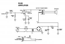
I should recive components by Monday.
Thank you very much for your help, I will post an update when im done.
And I guess that i can keep 68k 400v poliester capacitor connected over the mains? Its soldered on mains socket that I just salvaged from computer power supply.
The safety marks and the "x2" designation should be stamped on the capacitor body. If they are missing, remove the capacitor because it may be unsafe. On this circuit it will not be useful anyway; the correct position on tube amps is after the mains switch, in parallel with the power transformer primary winding. It will then remove the "click" noise when the amplifier is turned off.
Ok, if is in no use I wil remove it. ThanksThe safety marks and the "x2" designation should be stamped on the capacitor body. If they are missing, remove the capacitor because it may be unsafe. On this circuit it will not be useful anyway; the correct position on tube amps is after the mains switch, in parallel with the power transformer primary winding. It will then remove the "click" noise when the amplifier is turned off.
Project update
Here are some pictures of amp. This is pretty much final look, except for EL84 that I havent insert yet... And I will add name with gold color on front plate. I`am thinking of a name right now... maybe "Simplex" since the circuit is really simple.
Yesterday i modified the housing and painted it. I want oldschool look so I just grinded it with angle grinder for rough surface, then painted it black and after that I applied quick light coat of gold for shiny sparkles effect.
I hope that paint will stay on, since I didn`t use primer.
Parts will not arrive before Thursday 😡
Front:
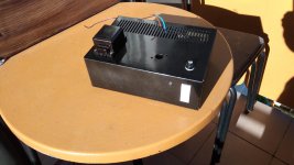
Back:
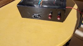
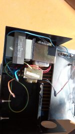
Inside, I used two 220-24v transformers to make isolation transformer (temporarily solution till I get real one ) :
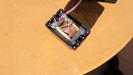
I mounted output transformer into casing of old doorbel transformer. That way it looks better and it`s safe to mount it outside on the casing.
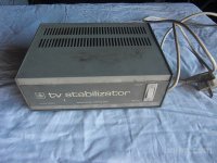
This is how housing looked before, it was voltage stabilizer for TVs, used in old days:
Here are some pictures of amp. This is pretty much final look, except for EL84 that I havent insert yet... And I will add name with gold color on front plate. I`am thinking of a name right now... maybe "Simplex" since the circuit is really simple.
Yesterday i modified the housing and painted it. I want oldschool look so I just grinded it with angle grinder for rough surface, then painted it black and after that I applied quick light coat of gold for shiny sparkles effect.
I hope that paint will stay on, since I didn`t use primer.
Parts will not arrive before Thursday 😡
Front:

Back:

Inside, I used two 220-24v transformers to make isolation transformer (temporarily solution till I get real one ) :

I mounted output transformer into casing of old doorbel transformer. That way it looks better and it`s safe to mount it outside on the casing.

This is how housing looked before, it was voltage stabilizer for TVs, used in old days:

Nice recycling; be sure to follow your local electrical code for the 230V wiring. On my low-cost builds with makeshift chassis, I use the Amazon items B005FPCN82 (wood) or B011CZGZIM (alluminium, with a nice anodization). The Amazon ASIN codes works on all EU and UK Amazon sites. The first one may be completed by an aluminium top plate; several low power low-cost Taobao/Aliexpress tube kits are using this exact same cheap but sturdy and good looking bamboo box.
Your chassis looks a bit cramped. If you hear hum on the output, put more distance between the tube socket and the power transformers. Try to visualize the dispersed magnetic field as a "cloud" around each power transformer; you don't want this hum inducing electromagnetic field to reach the tube grid.
Be sure to put enough insulation between the primary side of the output transformer wiring and the chassis.
I always recycle if I can. I reuse as much old stuff as I can to keep the cost down.Nice recycling; be sure to follow your local electrical code for the 230V wiring. On my low-cost builds with makeshift chassis, I use the Amazon items B005FPCN82 (wood) or B011CZGZIM (alluminium, with a nice anodization). The Amazon ASIN codes works on all EU and UK Amazon sites. The first one may be completed by an aluminium top plate; several low power low-cost Taobao/Aliexpress tube kits are using this exact same cheap but sturdy and good looking bamboo box.
Your chassis looks a bit cramped. If you hear hum on the output, put more distance between the tube socket and the power transformers. Try to visualize the dispersed magnetic field as a "cloud" around each power transformer; you don't want this hum inducing electromagnetic field to reach the tube grid.
Be sure to put enough insulation between the primary side of the output transformer wiring and the chassis.
Yes, it's a bit cramped because of those two big transformers, they are there temporarily. Can this magnetic field damage the tube? I don't want to drill another hole in housing as I plan to install real, smaller isolation transformer, that I will mount into corner. Yes, I applied electrical tape around output transformer. I will check electrical codes. Thanks
Last edited:
If your insulation transformer is toroidal, you may even remove the filament transformer, just wrap the required number of 15awg copper wire turns around the core. On the 117-6060 RS Components transformer each turn is 0,275 volts; so 12+12 turns will make 6,3V center tapped. Copper enameled transformer wire may be sourced from a old transformer.
They're will be no damage to the tube, just the possibility of a little hum. It's also advisable to adjust the position of the output transformer relative to the power transformers to minimise pickup of hum. You can use the "headphone trick" for that purpose.
Sent from my phone with Tapatalk. Please excuse any typpos.
Sent from my phone with Tapatalk. Please excuse any typpos.
- Status
- Not open for further replies.
- Home
- Amplifiers
- Tubes / Valves
- EL84 amp
