Hello, i'm new to tube amps, however i have experience with newer equipment and I would need a little bit of help.
I have extracted EL84 amp from old records player and installed it in new housing.
There is only one tube on the amp-EL84 and there is no preamp.
I don't have schematic, i searched for it and asked if anyone has it on slovenian forum since records player was made by slovenian "Iskra", but no luck.
I there will be need for schematic I will draw it, but I would rather not, because in order to do that I will need to take apart whole amp to see all of it.
Amp has live ground -one wire from mains is connected directly to chassis.
I burned my pc's sound card because amp have live ground (other equipment thats not earthed works fine). Will adding 1:1 isolating transformer to input solve this problem?
I added 470uF cathode bypass capacitor and it sounds alot better and louder.
Amp hums when no audio source is plugged, if i turn it off (by swich -than disconnect only one of mains wires) it hums even louder, if i disconnect mains from wall hum stops.
I have readed somewhere that bad filtering capacitor or bad coupling capacitors might be cause the hum, on what side of board can I look for them?
Currently i am using ic preamp to make it louder, i will build tube preamp in the future (all above problems are the same with or without preamp).
Thank you for your help!
Before you even think about plugging that thing in again, get an isolation transformer and install it! It is incredibly dangerous as is and will need to be updated to modern safety standards before you can work on it correctly.
(It is against forum rules to design or discuss live-mains connected power supplies, unless the intent is to install an appropriate isolation transformer.)
Get us a pic of the circuit at least, it will help us figure out what is going on, and how to advise you.
(It is against forum rules to design or discuss live-mains connected power supplies, unless the intent is to install an appropriate isolation transformer.)
Get us a pic of the circuit at least, it will help us figure out what is going on, and how to advise you.
A picture of the amplifier would be useful. Adding the insulation transformer is the first thing to do. It will also solve most of the hum issue. The cheapest are toroidal and have two identical 115/120v primary windings and two identical 115/120v secondary windings. Just connect in series the two primary windings, and the two secondary windings. Do not connect toghether the primary with the secondary, of course. Are you sure that the tube is EL84? 1960-65 mono record players were usually fitted with the ECL86 tube, or UCL82 with filament supply (50v) connected to a auxiliary winding of the motor.
That's exactly what I was thinking. It might even be a PCL86.. Are you sure that the tube is EL84? 1960-65 mono record players were usually fitted with the ECL86 tube, or UCL82 with filament supply (50v) connected to a auxiliary winding of the motor.
My personal advice is to forget about the original circuit design, and just build a known good design from scratch. The output transformer may be OK, but I suspect there won't be much useful life left in the one valve. The electrolytic caps would need replacing, and the resistors will probably be noisy carbon comps. The original signal caps may however still be usable, and may even be valuable, for example if they're mustard caps. So basically it doesn't make much sense to try and restore the original circuit.
Sent from my LG-D801 using Tapatalk
Currently I am using bluetooth audio module as power source, so there is no real connection between player and amp. Its EL84. I will post some images in the morning. Thanks
Love it, Slovenian piece from the cold war with a lone EL84. Who wants to play "How Sleazy is It?"
How about: Cut-throat B+ supply and a 25W resistor running the tube heater. High-output - like 10V RMS - ceramic-crystal cartridge feeds straight into the volume control and then the grid of the EL84.
Can't be getting the heater voltage from the motor, as he's separated the turntable from the amp.
How about: Cut-throat B+ supply and a 25W resistor running the tube heater. High-output - like 10V RMS - ceramic-crystal cartridge feeds straight into the volume control and then the grid of the EL84.
Can't be getting the heater voltage from the motor, as he's separated the turntable from the amp.
Yes, i changed it with another 220v-12v transformerLove it, Slovenian piece from the cold war with a lone EL84. Who wants to play "How Sleazy is It?"
How about: Cut-throat B+ supply and a 25W resistor running the tube heater. High-output - like 10V RMS - ceramic-crystal cartridge feeds straight into the volume control and then the grid of the EL84.
Can't be getting the heater voltage from the motor, as he's separated the turntable from the amp.
Yes, i changed it with another 220v-12v transformer
Changed which for a 220v - 12v xfmr? How was / is the 6.3V heater for the EL84 being supplied?
No offense, but very little of what you've said so far makes any sense..
Last edited:
Changed which for a 220v - 12v xfmr? How was / is the 6.3V heater for the EL84 being supplied?
No offense, but very little of what you've said so far makes any sense..
I measured voltage on turntable's motor that was supplying the heater and it was 12vac, wires were going to lighbulb (power indicator) and than to heater. I'm not sure if there is any resistor in between to drop down voltage. I will check later when I get home.
As this is a bargain basement record player it is extremely likely that the OPT is very poor quality. My guess is that the only thing worth saving from this is the EL84 - and even that only if it has not had much use over the years.
And i have another question... Is this pinout of socket or of tube when your loking at pins turned towards you? Thank you

Poslano z mojega S50 z uporabo Tapatalk
Poslano z mojega S50 z uporabo Tapatalk
I will go ahead and build new circuit. If tube will go bad after time I will buy new one. But sounds good even with this setup. CheersAs this is a bargain basement record player it is extremely likely that the OPT is very poor quality. My guess is that the only thing worth saving from this is the EL84 - and even that only if it has not had much use over the years.
Poslano z mojega S50 z uporabo Tapatalk
Jeeze, it ran a 6V lamp in series with the heater for the tube. I guess that's one way to make it go.. =/
You've got that right. It sounds like a pretty cheap & cheery piece of equipment, and basically worthless so far as chassis re-use is concerned. Even at its best, it's a 2W SE amp with no pre-amp and a thoroughly dangerous power supply. Not even worth the requisite isolation transformer.
@diy1995
IMHO - Find something else to work with, if you want to have anything worth owning. For your time, trouble and money, you can make something much more functional and rewarding.
Tube socket pins are always numbered in the clockwise direction, starting from the 'key' or gap, from +underneath+ the chassis. So yes, same as looking at the bottom of the tube.
The socket itself may have numbers molded into it.
As this is a bargain basement record player it is extremely likely that the OPT is very poor quality. My guess is that the only thing worth saving from this is the EL84 - and even that only if it has not had much use over the years.
You've got that right. It sounds like a pretty cheap & cheery piece of equipment, and basically worthless so far as chassis re-use is concerned. Even at its best, it's a 2W SE amp with no pre-amp and a thoroughly dangerous power supply. Not even worth the requisite isolation transformer.
@diy1995
IMHO - Find something else to work with, if you want to have anything worth owning. For your time, trouble and money, you can make something much more functional and rewarding.
And i have another question... Is this pinout of socket or of tube when your loking at pins turned towards you?
Tube socket pins are always numbered in the clockwise direction, starting from the 'key' or gap, from +underneath+ the chassis. So yes, same as looking at the bottom of the tube.
The socket itself may have numbers molded into it.
Last edited:
It was parallel with the bulb, i will build new circuit for this tube. Is there any good schematic as simplest as possible to keep the cost down and will sound good?Jeeze, it ran a 6V lamp in series with the heater for the tube. I guess that's one way to make it go.. =/
You've got that right. It sounds like a pretty cheap & cheery piece of equipment, and basically worthless so far as chassis re-use is concerned. Even at its best, it's a 2W SE amp with no pre-amp and a thoroughly dangerous power supply. Not even worth the requisite isolation transformer.
@diy1995
IMHO - Find something else to work with, if you want to have anything worth owning. For your time, trouble and money, you can make something much more functional and rewarding.
Tube socket pins are always numbered in the clockwise direction, starting from the 'key' or gap, from +underneath+ the chassis. So yes, same as looking at the bottom of the tube.
The socket itself may have numbers molded into it.
I would also keep the output transformer
Poslano z mojega S50 z uporabo Tapatalk
It all depends on what you mean by "sound good". My guess is that the OPT is tiny, and barely good enough for a guitar practice amplifier. Certainly inadequate for reproducing music.
Yes its tiny, I will replace it if I have to. Im not trying to make guitar amp, just for playing music from pc, phone, etc...It all depends on what you mean by "sound good". My guess is that the OPT is tiny, and barely good enough for a guitar practice amplifier. Certainly inadequate for reproducing music.
Poslano z mojega S50 z uporabo Tapatalk
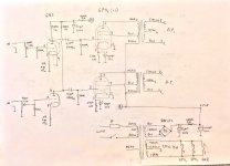
The attached schematic is a ultra-cheap 3+3w chinese kit based on 6p14 (similar to el84 / 6bq5) and 6n2 (similar to ecc83 / 12ax7). It has been designed to be assembled by unskilled people with the worst and cheapest components available and still sound good. I had one of them briefly and it was actually enjoyable, altough no match with a "real" hi-fi amplifier. Still a improvement over the average plastic bluetooth speaker sold today on most consumer electronic shops.
To use the EL84 tube, leave pin 1 of the socket unconnected (do not tie it to the ground; this will damage your vintage tube). To use the ECC83 tube, rewire the filament heater at pins 4, 5 and 9. To use your 12V filament transformer, connect a dropper resistor in series with the winding to reduce the voltage to 6.3V.
You can start the build as soon as you get the insulation transformer. Nothing in this circuit is critical. You may change component values slightly to fit the parts you have. The high voltage capacitors and the rectifier are easily grabbed from a discarded TV or computer power supply. If you omit the preamp tube completely, about 100/200 mW output power will be still available when you connect the amplifier to the computer line out. If you are using the orignal high efficiency speaker, this means a nice volume. If the output transformer does not have the ultralinear tap (blue wire in the schematic), connect pin 9 to pin 7 with a 100 ohm resistor (i's called triode mode).
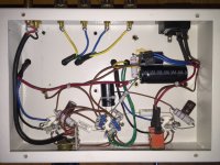
The picture shows a possible implementation: as you can see, it's very basic and simple. I haven't built this specimen. There are multiple violation of the electrical code on the wiring of the primary side of the transformer. Safety ground should be connected to the chassis and the wire should be mains rated. There are lethal voltages inside a tube amp. Build this at your own risk.
To use the EL84 tube, leave pin 1 of the socket unconnected (do not tie it to the ground; this will damage your vintage tube). To use the ECC83 tube, rewire the filament heater at pins 4, 5 and 9. To use your 12V filament transformer, connect a dropper resistor in series with the winding to reduce the voltage to 6.3V.
You can start the build as soon as you get the insulation transformer. Nothing in this circuit is critical. You may change component values slightly to fit the parts you have. The high voltage capacitors and the rectifier are easily grabbed from a discarded TV or computer power supply. If you omit the preamp tube completely, about 100/200 mW output power will be still available when you connect the amplifier to the computer line out. If you are using the orignal high efficiency speaker, this means a nice volume. If the output transformer does not have the ultralinear tap (blue wire in the schematic), connect pin 9 to pin 7 with a 100 ohm resistor (i's called triode mode).
The picture shows a possible implementation: as you can see, it's very basic and simple. I haven't built this specimen. There are multiple violation of the electrical code on the wiring of the primary side of the transformer. Safety ground should be connected to the chassis and the wire should be mains rated. There are lethal voltages inside a tube amp. Build this at your own risk.
Attachments
Last edited:
Hello, thank you for the schematic, i modified it to suit my needs, could you take a look how I just ended wire going to red to power transformer, i deleted pin 1, removed preamp (for now) and what do I connect to B that i marked with red circle (im a car mechanic and I understand B or B+ as battery, but clearly there is no battery hehe).

My output transformer has 3 wires on primary, but its brown, blue, white

How should I connect them?
CIRCUIT - MY TRAFO
BLACK - BLUE
BLUE - WHITE
RED - BROWN
?
Thank you!
My output transformer has 3 wires on primary, but its brown, blue, white
How should I connect them?
CIRCUIT - MY TRAFO
BLACK - BLUE
BLUE - WHITE
RED - BROWN
?
Thank you!
Last edited by a moderator:
Oh and whats the value of first capacitor after the rectifier, 82uF, 52uF?Hello, thank you for the schematic, i modified it to suit my needs, could you take a look how I just ended wire going to red to power transformer, i deleted pin 1, removed preamp (for now) and what do I connect to B that i marked with red circle (im a car mechanic and I understand B or B+ as battery, but clearly there is no battery hehe).
View attachment 596054
My output transformer has 3 wires on primary, but its brown, blue, white
View attachment 596057
How should I connect them?
CIRCUIT - MY TRAFO
BLACK - BLUE
BLUE - WHITE
RED - BROWN
?
Thank you!
Poslano z mojega S50 z uporabo Tapatalk
- Status
- Not open for further replies.
- Home
- Amplifiers
- Tubes / Valves
- EL84 amp