Hello folks, thanks a lot for replies.
Soulmerchant,
To be honest I am 99.9 % sure i did not have it running without a load.I share the house with the other friends and when it comes to listen to my music I have to drag downstairs all equipment (amp, speakers, turntable, cd player) and always make sure that all is connected properly (+ terminal to + etc..)Once the session is over, all stuff gets back upstairs to my room.Unless the cables loosened in speakers terminals somehow as speaker's end of cables never get detached, only God knows.And then obviously, i would notice straight away that one channel does not work.
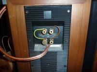
Only realised today - whether this was caused by the way i have these KEFs wired, they come with two pairs of terminals (HF,LF) - I bridged it so it should be connected sort of parallel. (attaching pic).
Have already been searching on how to fuse B+ but got discouraged by folks saying it may cause more harm then good etc.. But definitely interesting since this is kind of failure is very pricey to get fixed(£ 236 to be precise)
I think the DC voltage in filament being fine, found it matching the schematics. Nonetheless, will be replacing those 4700uF caps anyway.
Soulmerchant,
To be honest I am 99.9 % sure i did not have it running without a load.I share the house with the other friends and when it comes to listen to my music I have to drag downstairs all equipment (amp, speakers, turntable, cd player) and always make sure that all is connected properly (+ terminal to + etc..)Once the session is over, all stuff gets back upstairs to my room.Unless the cables loosened in speakers terminals somehow as speaker's end of cables never get detached, only God knows.And then obviously, i would notice straight away that one channel does not work.
Only realised today - whether this was caused by the way i have these KEFs wired, they come with two pairs of terminals (HF,LF) - I bridged it so it should be connected sort of parallel. (attaching pic).
Have already been searching on how to fuse B+ but got discouraged by folks saying it may cause more harm then good etc.. But definitely interesting since this is kind of failure is very pricey to get fixed(£ 236 to be precise)
I think the DC voltage in filament being fine, found it matching the schematics. Nonetheless, will be replacing those 4700uF caps anyway.
Attachments
LJT
Yes i did, it was some cheap DM from ALdi or Lidl. It was good stuff though. Fuse was ok unfortunately, so i went to Maplin and got myself DM which also reads caps up to 100uF..
De-coupling caps: hm, did not have a clue that this is quite more complicated topic then some basic RC filter.Will do my reading, thank for the link.
The stock valves Precisions are EL34, i also have these JJ EL34 II, i definitely want to try 5881, but when that will be since a lot of money went for those OTs..
Here is the link:
[Wanted -] Valves required for Audio Innovations S500 - Private Member Classifieds - HiFi WigWam
The caps:
Well, already received deliveries today, will give them a go to see if it affects anything but deffo going back to stocks if these prove to be still any good.
May well sell surplus stock then lol
You know, all this stuff is highly addictive once i start thinking of audio caps and best sockets I probably end up doing it..
Yes i did, it was some cheap DM from ALdi or Lidl. It was good stuff though. Fuse was ok unfortunately, so i went to Maplin and got myself DM which also reads caps up to 100uF..
De-coupling caps: hm, did not have a clue that this is quite more complicated topic then some basic RC filter.Will do my reading, thank for the link.
The stock valves Precisions are EL34, i also have these JJ EL34 II, i definitely want to try 5881, but when that will be since a lot of money went for those OTs..
Here is the link:
[Wanted -] Valves required for Audio Innovations S500 - Private Member Classifieds - HiFi WigWam
The caps:
Well, already received deliveries today, will give them a go to see if it affects anything but deffo going back to stocks if these prove to be still any good.
May well sell surplus stock then lol
You know, all this stuff is highly addictive
once i start thinking of audio caps and best sockets I probably end up doing it..After 25+ years its a good idea to replace all electrolytic caps.
The only exception with this amp is that the two 220uF power caps might still be good. They have been in the 4-5 examples I have worked on.
That is what I thought, though could not know about these filtering caps, maybe i would not order, maybe i would.
Will try to sell them if of no use to me, i can get those KEMETS as long as RS components still does them, literally across the road for me..
Hello folks, thanks a lot for replies.
Soulmerchant,
To be honest I am 99.9 % sure i did not have it running without a load.I share the house with the other friends and when it comes to listen to my music I have to drag downstairs all equipment (amp, speakers, turntable, cd player) and always make sure that all is connected properly (+ terminal to + etc..)Once the session is over, all stuff gets back upstairs to my room.Unless the cables loosened in speakers terminals somehow as speaker's end of cables never get detached, only God knows.And then obviously, i would notice straight away that one channel does not work.
Only realised today - whether this was caused by the way i have these KEFs wired, they come with two pairs of terminals (HF,LF) - I bridged it so it should be connected sort of parallel. (attaching pic).
Have already been searching on how to fuse B+ but got discouraged by folks saying it may cause more harm then good etc.. But definitely interesting since this is kind of failure is very pricey to get fixed(£ 236 to be precise)
I think the DC voltage in filament being fine, found it matching the schematics. Nonetheless, will be replacing those 4700uF caps anyway.
I've put HT fuses in 4 or 5 of these, right after the 1st dropping resistor, before the second 220uF cap. I've done the same kind of thing in other amplifiers if it is necessary. They can not be heard whatsoever. Implentation is not difficult. I used sand filled ceramic slow-blow T-250mA 440VAC type. If they do fail they will not "explode". Up to you - I have more than I need.
Your unit is a later model. The earlier ones had Hinchley Mains and OPT's which were superb. The later ones did not. The Hinchley's had 4, 8 and 12 ohm secondaries so are easy to spot.
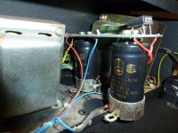
Your EL34 cathode resistors are mounted on that rather large circuit board which were later implemented. This was a less than clever "innovation", as the earlier models had them attached to the chassis with epoxy which helped dissipate heat. I have seen nice dark heat marks on some of those boards.... I also see the blue Philips cathode by-pass caps on the board as well
In two of the units I serviced, the DC filament bridge had gone - they sometimes used very cheap components. It looks like they used a cheaper HT bridge as well in your version. How sad - decent quality rectifier bridges are fairly inexpensive today.
The HT circuit board appears also to be a newer "innovation" that makes little sense. This is the first time I see this board. It would perhaps make implementing a HT fuse a bit of a bother.
I've just gone over another AI "first" amplifier. As in all of them, the electrolytics needed replacing. Believe it or not, I had to de-gauss one of the Hinchley OPT's in that amplifier. It now sounds better than new.
Last edited:
Yes i would like some of those fuses, can you pm me how much for it please?
I am aware my amp is the later model, i would love to hear the earlier model how that may sound like. Must be a pleasure to listen to it.
Hm, these cathode resistors - interesting, see this:
Amplifier Audio Innovations Series 500
That is apparently model with 4,8,16 Ohms taps, yet the cathode resistors are mounted exactly the same way as in my amp.But can clearly see those dark mark due to heat.
I am planning to eventually leave out the bottom grill which covers the access to PCBs or replaced it with something more suitable as to aid airflow.I bought 14cm low speed fan, very quiet one, will run it through Zalman fanmate to further drop rpm, hoping that it will force some airflow into chasis from bottom. Or may use faster 12 cm one.
It will all depend on how disturbing background noise that fan will be generating.Hope it will not be that bad, it indeed run very quite that 14 cm one.
Would figure out somehow how to get that fuse in there, no worries.
To be honest, those few minutes I was listening to the music with the new OTs fitted in, I was impressed somehow. Although run through those stock Precisions, and mismatched ECC88s (one stock precision, the second Brimar) it simply amazed me.(when i brought it over from sister some valves were missing, so i bought few just to see if it works at all, hence such a mismatch).
I do normally have 2x Siemens ECC88 in there.
So one would wonder if it was down to those cathode bypass caps replacement (2 x Jantzen bipolars) or new OTs added to it too..
Those blue caps are now enjoying their retirement, boxed underneath my bed Not sure if these are Phillips as it does not say anywhere.
The caps i ordered come from mouser.co.uk (although shipped from USA), to get a free delivery i had to place an order over £33, so all caps I chose i had to add some more + i decided for two bridge rectifiers (400V ones). No idea how good these are though.
I am aware my amp is the later model, i would love to hear the earlier model how that may sound like. Must be a pleasure to listen to it.
Hm, these cathode resistors - interesting, see this:
Amplifier Audio Innovations Series 500
That is apparently model with 4,8,16 Ohms taps, yet the cathode resistors are mounted exactly the same way as in my amp.But can clearly see those dark mark due to heat.
I am planning to eventually leave out the bottom grill which covers the access to PCBs or replaced it with something more suitable as to aid airflow.I bought 14cm low speed fan, very quiet one, will run it through Zalman fanmate to further drop rpm, hoping that it will force some airflow into chasis from bottom. Or may use faster 12 cm one.
It will all depend on how disturbing background noise that fan will be generating.Hope it will not be that bad, it indeed run very quite that 14 cm one.
Would figure out somehow how to get that fuse in there, no worries.
To be honest, those few minutes I was listening to the music with the new OTs fitted in, I was impressed somehow. Although run through those stock Precisions, and mismatched ECC88s (one stock precision, the second Brimar) it simply amazed me.(when i brought it over from sister some valves were missing, so i bought few just to see if it works at all, hence such a mismatch).
I do normally have 2x Siemens ECC88 in there.
So one would wonder if it was down to those cathode bypass caps replacement (2 x Jantzen bipolars) or new OTs added to it too..
Those blue caps are now enjoying their retirement, boxed underneath my bed
Not sure if these are Phillips as it does not say anywhere.The caps i ordered come from mouser.co.uk (although shipped from USA), to get a free delivery i had to place an order over £33, so all caps I chose i had to add some more + i decided for two bridge rectifiers (400V ones). No idea how good these are though.
Hi folks,
Did not go via 5881s since there was no much to read about these on internet, if anything then it had to with either Sovtek 5881WXT or WGC (can't remeber exactly)and then Tungsol 5881 in guitar amps.
I decided at the end for Tungsol 6L6GC STR re-issue, looks cool sounds fine....
Will post another story about the pre-amp ECC83 Svetlana Winged C piece of sh*t..
I am about to do fuse mode, and since i do not want to de-solder stock bridge rectifier off that PCB, i wonder whether i can use new one instead, (have it already at home):
http://www.mouser.co.uk/search/ProductDetail.aspx?r=583-BR310
The stock one is IR KBPC108, the specs seem to me similar, but you know certainly i am not an expert. So the question is:
Is that BR-310 at least equally bad, or slightly better than KBPC108?
Soulmerchant,
Is it ok to use fuse socket or should I just solder the wires directly to fuse?
(That may sound like a silly question but i can imagine some folks may raise a concern over how that socket may affect the sound)
Also, is it ok to design a simple PCB or better to just solder the resistor,fuse and caps together via wires?
Apologise about such a quick post, dead busy during the week..
Attachments
There is a common fault with the design, just looking at the screen grid voltage shows up an issue.
Use a 1k2 3W resistor instead of 100R in the screen. That will stop the EL34s from shorting and taking out the transformer or better still use 6L6GC.
Some of the transformers were wound in Parkstone, Dorset, others at Reading Windings.
The BHC caps were made less than 250yards away from Richard's AI factory Unit, in Weymouth.
Nice to no air miles being used.
There is a common fault with the design, just looking at the screen grid voltage shows up an issue.
Use a 1k2 3W resistor instead of 100R in the screen. That will stop the EL34s from shorting and taking out the transformer or better still use 6L6GC.
Some of the transformers were wound in Parkstone, Dorset, others at Reading Windings.
The BHC caps were made less than 250yards away from Richard's AI factory Unit, in Weymouth.
Nice to no air miles being used.
Thanks Jon,
I can imagine those guys across the yard to get some caps lol when running low on stock.
6L6GCs are my nr.1 choice since they sound fine to me, and importantly enough, the amp does not get as hot as when with EL34s..
May though play some music through these once i get them back from testing as long as they still be ok..(just for a comparison).
Thanks for the suggestion about the R value, great to have all what i need here in this post, should i wish to go back to EL34s..
Richard was a good friend and we did a lot of work together in the electronics industry. I have been a service engineer for over 45 years, he was a good salesman and we came up with some good designs in the past.
The Ai with the 2A3s was novel! Absolute fortune for the 2A3s as we had IO bases fitted to them.
The Ai with the 2A3s was novel! Absolute fortune for the 2A3s as we had IO bases fitted to them.
Hello,
The JJ EL34 II were tested and found to be absolutely ok.
Had to sent them over to Bristol to Amploft – A haven for troubled amplifiers as could not find any such service here in Northamptonshire. Mike seem to be great person, perfect service from him.
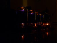
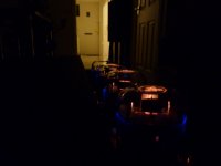
Meanwhile, these 6L6GC-STRs are just nice, even please the eye lol..
Switched it on one of the evenings and to be honest panicked a bit first..
I am off on Friday, will finally get it fused.
The JJ EL34 II were tested and found to be absolutely ok.
Had to sent them over to Bristol to Amploft – A haven for troubled amplifiers as could not find any such service here in Northamptonshire. Mike seem to be great person, perfect service from him.
Meanwhile, these 6L6GC-STRs are just nice, even please the eye lol..
Switched it on one of the evenings and to be honest panicked a bit first..
I am off on Friday, will finally get it fused.
Attachments
Richard was a good friend and we did a lot of work together in the electronics industry. I have been a service engineer for over 45 years, he was a good salesman and we came up with some good designs in the past.
The Ai with the 2A3s was novel! Absolute fortune for the 2A3s as we had IO bases fitted to them.
Jon
Btw, when I was deciding between 5881 or 6L6GC I came across one of your posts where you said that 6L6GC is one of the best tubes for audio so I ditched the idea of 5881 route and bought 6L6GCs..
JonSnell,
I have an AI800, that has experienced several cases of "Meltdown". I addressed this in the thread http://www.diyaudio.com/forums/tubes-valves/296507-el34-internal-shorts.html
Just like you recommended Cluster One to increase g2 resistors to 1K2, I was given similar advice. Searching the forum for information on this resistor, I have a feeling that that it is the "kinkless" design of the 6L6 that does the trick, would you agree that replacing with a KT77 is a "safe" alternative to using 6L6? Would you recommend increasing g2 resistors even when using 6L6 or KT77?
Lately I have also investigated into the Floating Paraphase type phase splitter.
What worries me about the design used by AI is that the resistors connected to the grid of the "inverter" tube is also serving as grid resistor for the output tubes. How would this effect the splitter if tubes are driven into A2 mode or if experiencing capasitor blocking?
There is a common fault with the design, just looking at the screen grid voltage shows up an issue.
Use a 1k2 3W resistor instead of 100R in the screen. That will stop the EL34s from shorting and taking out the transformer or better still use 6L6GC.
Some of the transformers were wound in Parkstone, Dorset, others at Reading Windings.
The BHC caps were made less than 250yards away from Richard's AI factory Unit, in Weymouth.
Nice to no air miles being used.
Thank you Jon for your kind advice.
Within a few days I receive my 2nd AI S500 MkI with 3 output taps. I sold my 1st S500 almost 14 years ago; since that time I discovered state of the art loudspeakers well suited to 25W tube amps.
Does your advice above apply to my MkI S500? OP subject is a latter S500 with only 2 output taps.
- Status
- This old topic is closed. If you want to reopen this topic, contact a moderator using the "Report Post" button.
- Home
- Amplifiers
- Tubes / Valves
- Audio Innovations 500 output transformer