Audio Innovations 500 output transformer - Solved
Hi folks,
Hope that someone can poke me in the right direction - how to go about output transformer (replacement or rewind?).
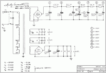
My AI 500 is currently out of service, this is the model with 4 & 8 ohm taps - the 47R 11W (the one just after rectifier, between those two 220uF/400V caps) went up in smoke & fire. It literally burnt.
I naively thought (to be more exact i hoped) that this was down to its age/deterioration so bought some 10W47R from Maplin, soldered it in, switched it on, a pop in speakers and dead silence followed. No hum or anything, just pure Sound of Silence 🙄
To cut the story short - apparently left channel output transformer primary & secondary windings are shortcircuited, DMM shows 12 ohms between yellow wire (i assume B+ wire on in schematics) and any wire on the secondary side (blue, red or green)
It also seem to be circuit-open between yellow & green or blue on primary side.
The following are the readings should someone benefit from it or eventually advise if those are normal (sensible) values):
(-the color of wires matches schematics)
Left channel:
B+, green = 0 Ohm
B+, blue = 0 Ohm
B+ violet = 22.9 Ohm
B+,black = 55 Ohm
green, blue = 26.5 Ohm
Right channel:
B+, green = 20.1 Ohm
B+, blue = 46.7 Ohm
B+, violet = 22.5 Ohm
B+, black = 54.9 Ohm
green, blue = 26.1 Ohm
The broken transformer has resistance of 12 Ohm between B+ and minus/earth (blue wire on secondary winding)
The good one shows resistance of the values 0.550 MOhm between B+ and minus/earth (blue wire on secondary winding) although this number likes to go up to 0.8 - it actually fluctuates.
Can someone please advise:
1.) buying a replacement - where from?
2.) rewinding - where/what company does this & what
are the parameters/specification of this transformer or where to get these from?
3.)buying second hand if anyone happens to have one 😛
In case of buying a replacement, would it not be a better idea to replace also the working output transformer so that those two are similar in parameters?
No idea why this all happened but could it be that i had Xduoo x3 hooked to it via AUX therefore simply overloaded it?
By the way, when listening to the vynils - I could turn the volume pot to max and it would be loud.
When listening to CD, anything over 90 degree knob - the music was way too loud.
The rest of the components inside seem to be fine, no strange looking colors or burns, can supply photo if anyone needs it.
Also i believe that it is all still original components inside.
So i hope that there is a solution to my current misery 🙂
I can imagine this may to be quite costly repair,hope that it will turn to be some reasonable price.
Thanks for reading & help.
Hi folks,
Hope that someone can poke me in the right direction - how to go about output transformer (replacement or rewind?).
My AI 500 is currently out of service, this is the model with 4 & 8 ohm taps - the 47R 11W (the one just after rectifier, between those two 220uF/400V caps) went up in smoke & fire. It literally burnt.
I naively thought (to be more exact i hoped) that this was down to its age/deterioration so bought some 10W47R from Maplin, soldered it in, switched it on, a pop in speakers and dead silence followed. No hum or anything, just pure Sound of Silence 🙄
To cut the story short - apparently left channel output transformer primary & secondary windings are shortcircuited, DMM shows 12 ohms between yellow wire (i assume B+ wire on in schematics) and any wire on the secondary side (blue, red or green)
It also seem to be circuit-open between yellow & green or blue on primary side.
The following are the readings should someone benefit from it or eventually advise if those are normal (sensible) values):
(-the color of wires matches schematics)
Left channel:
B+, green = 0 Ohm
B+, blue = 0 Ohm
B+ violet = 22.9 Ohm
B+,black = 55 Ohm
green, blue = 26.5 Ohm
Right channel:
B+, green = 20.1 Ohm
B+, blue = 46.7 Ohm
B+, violet = 22.5 Ohm
B+, black = 54.9 Ohm
green, blue = 26.1 Ohm
The broken transformer has resistance of 12 Ohm between B+ and minus/earth (blue wire on secondary winding)
The good one shows resistance of the values 0.550 MOhm between B+ and minus/earth (blue wire on secondary winding) although this number likes to go up to 0.8 - it actually fluctuates.
Can someone please advise:
1.) buying a replacement - where from?
2.) rewinding - where/what company does this & what
are the parameters/specification of this transformer or where to get these from?
3.)buying second hand if anyone happens to have one 😛
In case of buying a replacement, would it not be a better idea to replace also the working output transformer so that those two are similar in parameters?
No idea why this all happened but could it be that i had Xduoo x3 hooked to it via AUX therefore simply overloaded it?
By the way, when listening to the vynils - I could turn the volume pot to max and it would be loud.
When listening to CD, anything over 90 degree knob - the music was way too loud.
The rest of the components inside seem to be fine, no strange looking colors or burns, can supply photo if anyone needs it.
Also i believe that it is all still original components inside.
So i hope that there is a solution to my current misery 🙂
I can imagine this may to be quite costly repair,hope that it will turn to be some reasonable price.
Thanks for reading & help.
Attachments
Last edited:
Try to find your local Audio Innovation dealer ( your user profile doesn't say where you are from). If you can get your hands on an original replacement transformer the amplifier value will be intact and you will not have problems with hole-spacing etc when replacing it.
It is probably cheaper to do that than finding a non-original replacement, since - as you mention yourself - you will need to replace both, and therefore double the cost.
Anyway, if your only option is to find a non-original replacement, you should surely be able to find some, since several other butique-amps and DIY projects uses EL34 with grid-feedback.
Last edited:
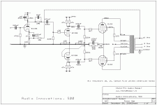
This is typical EL34 push-pull ultra-linear amp, you can use any suitable transformer, with 3.3 - 4.3K primary impedance.
Since you have one working output transformer, measure primary-secondary turns ration, and select suitable among available from many vendors / winders.
Since you have one working output transformer, measure primary-secondary turns ration, and select suitable among available from many vendors / winders.
I would have all the tubes tested before using them again. Tubes can kill (amps)!
Gosh, never thought these could be at fault.
It was a night when it all happened and the lights were turned off.
Obviously i could hear sound fading away, crackles in it and whatever, so i just reached and switched it off.
In between, the tubes, as the power was dying, were losing the heat and hence the light it creates was also dying.
Did not notice anything strange though, like purple light or those grey things inside being red...
Try to find your local Audio Innovation dealer ( your user profile doesn't say where you are from). If you can get your hands on an original replacement transformer the amplifier value will be intact and you will not have problems with hole-spacing etc when replacing it.
It is probably cheaper to do that than finding a non-original replacement, since - as you mention yourself - you will need to replace both, and therefore double the cost.
Anyway, if your only option is to find a non-original replacement, you should surely be able to find some, since several other butique-amps and DIY projects uses EL34 with grid-feedback.
Thanks,
I live in UK, Audio Innovation was based in Brighton, United Kingdom.
They went out of business long time ago unless i am wrong.
But, looks like these folks here Wound Components - Audio Applications are original equipment manufacturers for Audio Innovations. (at least they claim to be)
Will email them to see..
This is typical EL34 push-pull ultra-linear amp, you can use any suitable transformer, with 3.3 - 4.3K primary impedance.
Since you have one working output transformer, measure primary-secondary turns ration, and select suitable among available from many vendors / winders.
Thanks,
I will email to the Wound Components (link in my reply to Nrik) hoping that i can get original replacement if they really are original manufacturers..
That primary impedance - where does this come from? I kind of remember what it this but the schematics unfortunately do not state anything like this.
Is it that that ,,typical EL34 push-pull ultra-linear amp,, normally requires one or this is only related to Audio Innovations 500 amp? (sorry for silly question though).
For repair of your AI amplifier in the UK, you may want to contact Border Patrol
Audio Innovations
For non original, quality transformer, you may look at e.g. Sowter transformers
PUSH-PULL OUTPUT TRANSFORMERS or Hammond transformers or others to seek a suitable replacement that will fit inside the amplifiers casing.
I'm still a beginner with DIY tube amps, but got started when repairing an Audio Innovations 800 that had gone bad. Bellow follows my understanding of transformer impedance requirement, fellow members may chime in with corrections:
The requirement for primary inductance is determined by your choice of valves and their operating conditions and may be found in valve datasheets.
For example, in Ultra Linear PP amplifiers (like AI500) a nominal load between the anodes of 6k6 is recommended for EL34 http://www.r-type.org/pdfs/el34.pdf
It is my understanding that this value is for optimum output power, and that slightly higher values may improve distortion figures.
The transformer is there to transform the low speaker impedance up in order to mach the high impedance required by the valves. The impedance transformation ratio is the square of the voltage transformation ratio. Remember that practically no speaker is a flat 8 or 4 ohm, hence you should not be to focused on the exact load. Any transformer between 6k6 and 8k is likely to be OK. Hopefully someone with more experience than myself can chime in to verify, and may be expand on this.
The AI500 is not very different in its topology from the AI800 (although the drawings are made in a different fashion, so it may not be immediately recognizable). My general advice is:
A - Put a discharge resistor across the HT capacitors. For example between point "D" and GND. On my amp the capacitors held 300+ volts charge for several days. Remember to calculate required wattage of the resisitor.
B - Check the decupling capacitor across the 220ohm/10W cathode resistor. Make sure that it has no DC leakage. The AI800 is a slightly different design with individual, decupled, cathode resistors. On my amp 3 out of four were bad.
C - Replace the 100ohm resistors between transformer UL taps and valve with higher values. Make sure that they are mounted close to the valve. 1K seem to be the generally accepted value. On my AI800, two of these resistors had burned open circuit. It is my understanding that the original 100ohm are OK if you have rewired the valves for triode operation or if you're using kinkless valves like 5881 or 6L6GC,
D - Check the coupling capacitors between phase splitter and output tubes. They are rated at 400V. This should be sufficient, but some fellow board members felt it was on the low side in the case of my AI800, that also operate at 390V.
E - When the amp is back working, check the voltage across the second 220uF capasitors in the PSU. In the case of the AI800 it was recommended to increase this when with 240V mains. According to your diagram you should measure 390volts when all valves operate normally.
Thanks,
I will email to the Wound Components (link in my reply to Nrik) hoping that i can get original replacement if they really are original manufacturers..
That primary impedance - where does this come from? I kind of remember what it this but the schematics unfortunately do not state anything like this.
From turns ratio, that's why I asked turn ration.
See formula and online calculator here:
Transformer Turns Ratio Calculator
Is it that that ,,typical EL34 push-pull ultra-linear amp,, normally requires one or this is only related to Audio Innovations 500 amp? (sorry for silly question though).
It means this particular schematic is nowhere unique, many similar available with few mods.
LJT,
Thanks a lot for the valuable info, I will definitely make sure to check it all.
Also, thanks a lot to all of you ,,Welcome,Nrik,LinuksGuru,, for your time and help. Greatly appreciated.
Thanks a lot for the valuable info, I will definitely make sure to check it all.
Also, thanks a lot to all of you ,,Welcome,Nrik,LinuksGuru,, for your time and help. Greatly appreciated.
Yes, SP Wound did make transformers for AIThanks,
I live in UK, Audio Innovation was based in Brighton, United Kingdom.
They went out of business long time ago unless i am wrong.
But, looks like these folks here Wound Components - Audio Applications are original equipment manufacturers for Audio Innovations. (at least they claim to be)
Will email them to see..
Border Patrol are now based in the US. Their UK service agent is David Wright, he can sort your S500.
http://www.borderpatrol.net/aiind.htm
I have emailed David from Border Patrol as well as http://www.spwoundcomponents.co.uk/:
Geoff from spwoundcomponents replied that hey can supply and what part number it is.
David actually advised to order from spwoundcomponents, also advised on part number.
I think it is ex stock as for what i remember from my emails with Geoff and (should anyone need that) the part number is A6001/5.
Geoff from spwoundcomponents replied that hey can supply and what part number it is.
David actually advised to order from spwoundcomponents, also advised on part number.
I think it is ex stock as for what i remember from my emails with Geoff and (should anyone need that) the part number is A6001/5.
For repair of your AI amplifier in the UK, you may want to contact Border Patrol
Audio Innovations
For non original, quality transformer, you may look at e.g. Sowter transformers
PUSH-PULL OUTPUT TRANSFORMERS or Hammond transformers or others to seek a suitable replacement that will fit inside the amplifiers casing.
I'm still a beginner with DIY tube amps, but got started when repairing an Audio Innovations 800 that had gone bad. Bellow follows my understanding of transformer impedance requirement, fellow members may chime in with corrections:
The requirement for primary inductance is determined by your choice of valves and their operating conditions and may be found in valve datasheets.
For example, in Ultra Linear PP amplifiers (like AI500) a nominal load between the anodes of 6k6 is recommended for EL34 http://www.r-type.org/pdfs/el34.pdf
It is my understanding that this value is for optimum output power, and that slightly higher values may improve distortion figures.
The transformer is there to transform the low speaker impedance up in order to mach the high impedance required by the valves. The impedance transformation ratio is the square of the voltage transformation ratio. Remember that practically no speaker is a flat 8 or 4 ohm, hence you should not be to focused on the exact load. Any transformer between 6k6 and 8k is likely to be OK. Hopefully someone with more experience than myself can chime in to verify, and may be expand on this.
The AI500 is not very different in its topology from the AI800 (although the drawings are made in a different fashion, so it may not be immediately recognizable). My general advice is:
A - Put a discharge resistor across the HT capacitors. For example between point "D" and GND. On my amp the capacitors held 300+ volts charge for several days. Remember to calculate required wattage of the resisitor.
B - Check the decupling capacitor across the 220ohm/10W cathode resistor. Make sure that it has no DC leakage. The AI800 is a slightly different design with individual, decupled, cathode resistors. On my amp 3 out of four were bad.
C - Replace the 100ohm resistors between transformer UL taps and valve with higher values. Make sure that they are mounted close to the valve. 1K seem to be the generally accepted value. On my AI800, two of these resistors had burned open circuit. It is my understanding that the original 100ohm are OK if you have rewired the valves for triode operation or if you're using kinkless valves like 5881 or 6L6GC,
D - Check the coupling capacitors between phase splitter and output tubes. They are rated at 400V. This should be sufficient, but some fellow board members felt it was on the low side in the case of my AI800, that also operate at 390V.
E - When the amp is back working, check the voltage across the second 220uF capasitors in the PSU. In the case of the AI800 it was recommended to increase this when with 240V mains. According to your diagram you should measure 390volts when all valves operate normally.
LJT,
Have fitted the new OT, quite extensive job as to form cables although enjoyable though...
A - Completely forgot about this discharging resistor, perhaps will do as a part of upgrade i will mention later..
B - Was not sure how to check these capacitors for DC leakage hence both were replaced with 68uF 100Vdc Jantzen Bi-polar Electrolytic Capacitor(bought these from hificollective here in UK). I also bought pack of Panasonic FCs, however, since these are radial I preferred to fit in Jantzens as axial.
C - The resistors in mine amp are 150 Ohms 1% each, soldered directly to the valve sockets (between pin 4 and 6). Checked them, all keep value around 150 Ohms. I have been thinking of buying 5881s as apparently these put less strain on the amp than EL34 as well as out of curiosity how it then may sound like.Therefore I may replace these resistor to higher value sometimes later.
D - did not get much job done on checking if these work (i assume they do - we talk about those two 470nF/400V capacitors connected to the plates of ECC88).
What are the symptoms if these are not functioning properly?Could that be the cause that the OT went to heaven?
(I do apologise beforehand for the silly question, i am not an expert although I studied electronics subject good 20 years ago completely into depth)
E - this is the part where it all gets interesting:
When switched it on (speakers connected), couple of seconds into operation it made a strange noise like when you touch an input jack of guitar cable - it last few seconds but then all went back to normal.
(I thought this may have to do with some of those electrolytic caps of power supply, i know i may sound funny 🙄)
Left it to warm up for about 15 minutes observing the tubes and amp as such for fumes lol..Turning volume & balance knob to see if both channels working - fine..
Then the reference voltages were checked and i found them being dropped a bit.
Schematics my measurement
point D 380V 374V
point E 350V 337V
point F 300V 290V
point G 255V 249.7V
point H 175V 168.7V
point I 235V 224.8V
right channel the voltage on that 15 ohm cathode resistor :
schematics - 28V5
my measurement 26.55V
left channel
my measurement 26.49V
cathode resistor of ECC88s
schematics 1.8V
I had 1.804V vs 1.812V
cathode resistor of ECC83
schematics 1V
I had there 0.945V
The valves fitted in were stock Precisions, obviously will re-check the voltages with those JJ EL34 II too.
I decided to replace all electrolytic caps given that all are factory fitted (except two Jantzens I mentioned already).
Since being quite happy with the overall sound of this amp and not much into spending money on audio grade caps I ordered some Nichicons, one or two Vishays.
As for filtering caps 220uF/400V i chose this:
ALS30A221DA400 | KEMET Aluminium Electrolytic Capacitor 220μF 400 V dc 36mm Screw Terminal Can - Screw Terminals, Radial ALS30 Series | KEMET
but I also ordered:
http://www.mouser.co.uk/Search/Prod...rtualkey59850000virtualkey598-SLPX221M450H3P3
Am I right thinking that the KEMET one is a better choice?
(I swear by bible that i made my reading over what i should look for when choosing caps for power supply and ordered those Cornell Dubilliers , went back to read some more and panicked and ordered KEMETS since those should last longer, lower ESR, nice ripple etc.)
So the summary of what i would like to ask you is:
Is the KEMET caps i chose good/ok choice or some crap?
The voltages i checked - anything potentially very odd or still within reasonable tolerance taken into consideration that parts are over 25 years old?(I do not mind them as it gives me some calming feeling that amp is not pushed that hard but i want to be assured by you specialists..🙂)
Thanks a lot for your time and advice.
Great to see that your amp is back in operation.
Since you did not put a discharge resistor - remember to discharge manually next time you open the amp.
Your measured voltages seem OK to me. The value of the 47R resistor between the two 220uF capasitors seem to be fine, no need ot increase it. The cathode voltage of 26.5 indicate that your tubes run slightly less current than nominal at 56mA/valve compared to the design value of 60mA. It seems you have a nice balance between the two channels. Did you have someone check your valves with a valve tester? Maybe there is no need for your new JJ replacements?
Noise on startup: I had something similar. On my amp several of the pins of the valve sockets had lost its grip. Try gently touching each valve and see if the sound reappear.
I had limited success in cleaning the contacts points and checked the contact pressure by inserting a piece of wire in each hole if the socket. Next, I will have to replace all 9pin sockets. Some valves also has pin diameters slightly less than standard - this will increase the problem.
The valves themselves was cleaned using a "blue" led-pencil eraser.
Good call on replacing the two decoupling capasitors. Hopefully someone can chime in with the effect of reducing the value from 100 to 68 uF. Bi-polar is probably an overkill and the the 100v rating from the OEM may also be higher than required. According to information I received 64 volt would probably suffice.
So far I've only tested my AI800 with 6L6GC valves, if you ever test with other tubes than your please let me know. I am starting to suspect that it is the "Kinkless Tetrode" valve design that is the advantage with respect to valve longevity in AI amplifiers. In witch case there may be other valves than the Sovtec 5881 that will give good service life. My amp is a hack, with chassis parts missing, so it will never be the center piece of the living room. If the chassis had been nice and complete I would probably purchase KT77 from JJ or Genalex.
Capasitors: I have not experimented much with different brand capasitors or PSU filtering for that matter. I notice that OEM caps are rated at 400 volts. Now, you don't list the voltage at testpoint "C" in your PSU, but based on the schematics and current in the EL34s I anticipate approximately 385-390 volts. That does not leave to much margins with 400v spec of the Kemets. The voltage spec seem to favor the Cornell at 450v.
I also notice that the Cornel is for soldering/PSB mounting while the Kemet has screw on attachement - what is the OEM design like?
Still, my guts tell me to use Kemet, at least if the OEM caps use the same type of screw terminals.
Hello LJT
Thanks for reply.
I have learnt hard way about discharging such caps - my digital multimeter got fried thanks to that..😎
Have not had the valves tested yet, need to do some more search on this, the only guy around my area i managed to find online does not have a tester.
The other ones are far away hence the option will be shipping my valves to them, do not mind that for the peace of mind.
Interesting, I actually cleaned the valve sockets with WD40 Specialist Contact Cleaner, will see next time when switch it on if this kind of noise reappears.Perhaps another reason for upgrade is to get new sockets, but gosh if i imagine making sure everything is soldered back as it was before 😀
The 68uF/100V capacitors where factory fitted, I actually decided for axials in there that's why I opted for those Jantzens, the Panasoc FCs i bought as a back up are radials.Wanted it to look tidy, although I can imagine that radials can be folded there too.
I think that these caps and resistors they bypass are RC filters, so by changing capacitance one effectively moves cut-off frequency?(by de-creasing C the cut-off freq moves up a bit subsequently less portion of lower spectrum gets amplified?
Sovtecs 5881 apparently can be used in this amp without many modification required - i learnt it from other forum where the guy sort of passed on his conversation with David Wright (Board Control).I think they mentioned SOvtecs were preferred since proved to be most robust
So hopefully, once i get my bank account recovered i will buy quad of whatever 5881s I will like.
(I have bookmarked that conversation, let me know if you wish to read it, not sure if i can post links to different forums..)
I was kind of lazy to get the back cover open to check C voltage. But I will obviously do check with the original caps still on for the following reason:
These dropped voltages confused me a bit, and i thought it may have to do with the filtering caps not being in good condition (too much current leaking? + the age etc) so i decided to get some new caps.
KEMETs are screw caps, half ESR of the Cornells, better ripple current and much better life then Cornells, physical size similar to the stock caps whilst Cornells are half the size.
Sort of read too much about what to look for in PSU filtering caps and ended up ordering Kemets although i already had Cornells ordered.
The orig. caps specs:
220uF
400VDC
-10 +50%
55/085/56 LL
ALS20A 221 DD 400
To be honest, i would love to keep these in as for sentimental value they represent. So if i find that the caps have nothing to do with that voltage being dropped a bit i may well but them back.
Cornells are snap-in, would have to solder the wires on them and then to PCB..
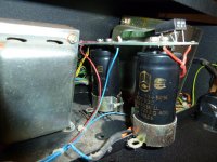
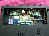
Attaching the pic, the green resistor is the one 47R 11W which went on fire, the transformer hidden behind the caps is mains, the one on left output T left channel.. The other picture it of PCB accessible from the bottom of amp - the voltage readings taken from there..
Thanks for reply.
I have learnt hard way about discharging such caps - my digital multimeter got fried thanks to that..😎
Have not had the valves tested yet, need to do some more search on this, the only guy around my area i managed to find online does not have a tester.
The other ones are far away hence the option will be shipping my valves to them, do not mind that for the peace of mind.
Interesting, I actually cleaned the valve sockets with WD40 Specialist Contact Cleaner, will see next time when switch it on if this kind of noise reappears.Perhaps another reason for upgrade is to get new sockets, but gosh if i imagine making sure everything is soldered back as it was before 😀
The 68uF/100V capacitors where factory fitted, I actually decided for axials in there that's why I opted for those Jantzens, the Panasoc FCs i bought as a back up are radials.Wanted it to look tidy, although I can imagine that radials can be folded there too.
I think that these caps and resistors they bypass are RC filters, so by changing capacitance one effectively moves cut-off frequency?(by de-creasing C the cut-off freq moves up a bit subsequently less portion of lower spectrum gets amplified?
Sovtecs 5881 apparently can be used in this amp without many modification required - i learnt it from other forum where the guy sort of passed on his conversation with David Wright (Board Control).I think they mentioned SOvtecs were preferred since proved to be most robust
So hopefully, once i get my bank account recovered i will buy quad of whatever 5881s I will like.
(I have bookmarked that conversation, let me know if you wish to read it, not sure if i can post links to different forums..)
I was kind of lazy to get the back cover open to check C voltage. But I will obviously do check with the original caps still on for the following reason:
These dropped voltages confused me a bit, and i thought it may have to do with the filtering caps not being in good condition (too much current leaking? + the age etc) so i decided to get some new caps.
KEMETs are screw caps, half ESR of the Cornells, better ripple current and much better life then Cornells, physical size similar to the stock caps whilst Cornells are half the size.
Sort of read too much about what to look for in PSU filtering caps and ended up ordering Kemets although i already had Cornells ordered.
The orig. caps specs:
220uF
400VDC
-10 +50%
55/085/56 LL
ALS20A 221 DD 400
To be honest, i would love to keep these in as for sentimental value they represent. So if i find that the caps have nothing to do with that voltage being dropped a bit i may well but them back.
Cornells are snap-in, would have to solder the wires on them and then to PCB..
Attaching the pic, the green resistor is the one 47R 11W which went on fire, the transformer hidden behind the caps is mains, the one on left output T left channel.. The other picture it of PCB accessible from the bottom of amp - the voltage readings taken from there..
Attachments
Most common root of opt transformer failure is running the amp no-load. This is especially true for pentodes.
The few times I have come across a real opt failure, the owner swears that they never turned it on without speaker load, but usually inspections of cables and speakers shows otherwise. Just don't let them blame the cat...
The AI-500 should have a B+ fuse inserted between the 220uF caps in the PSU. PM me and I will send you a couple.
An aside note, the 220uF caps I've seen are serious quality and haven't needed replacing. However pretty much all other caps, save the polystyrenes do need replacing. 105 degree Low ESR types are a good start. For cathode by-pass, look for Elna Cerafine or Nichicon muse. The generic blue philips caps that were standard were excellent stock 25+ years ago. Now they will have about half the capacitance left.... Also, if you are in the mood, replace the ERO mkt coupling caps with mkp's.
The first two 33uF caps in the PSU can easily be 100uF instead. The ones on the boards can be 33uF as you like.
The stock volume control is budget. I swapped it for a 250k Noble. If you use the phono, then it will benefit greatly from proper RIAA tuning. There are a few iterations of the phono circuit (some that were never even noted). Most are poor in some way. Today its easier to correct for RIAA though.
Also, the caps in the DC filament supply very likely need replacement. Especially so if you use the phono. I tuned the DC voltage in the last one I had to 6.3 vdc..
Best regards
Ian
Last edited:
I've had an AI500 for about 10 years in my main system. After a few quad of valves, my technician recommended lowering the output to around 18-20 W, instead of 25 W. I replaced the volume pot and put a soft-start circuit. I swapped the ERO caps to some quality Mundorf ones, but couldn't tell much of a difference. The military ERO do work mighty fine. There's no much room in there either...
The phono stage is a good piece of kit. Worth putting some work on it.
Regards,
Vincula
The phono stage is a good piece of kit. Worth putting some work on it.
Regards,
Vincula
Fried multimeter: There are fuses (sometimes soldered fuses) inside them. ave you checked?
Socket cleaning: Maybe start a separate tread on this forum on the topic of "reviving" old sockets?
Capasitors: Like Soulmerchant say: I doubt that the capasitors need replacement. I was of the impresion you wanted to do it as a precaution.
If you prefer to keep them, do that. I don't think they are the reason for your slightly low voltage readings.
De-coupling caps: According to your diagram the capasitors were supposed to be 100uF, but apparently 68uF was fitted by OEM. My worry was how the the change of LF cutoff frequency would affect stability, this appears to be unfounded.
You may find this ongoing discussion of interest: http://www.diyaudio.com/forums/tube...ube-cathode-bypass-mandatory-stereo-amps.html
Replacement tubes: Yes some AI "Fries tubes", my amp must have suffered this as least twice, and still the transformers survived, but PCB and several resistors were seriously damaged by heat. If you are still using the original valves I don't see much reason to move to 5881, although I would love to see the link you mention.
Voltages: The difference you see, I belive is quite normal. I believe that the spread you see can be explained by variation in resistor values and spread in tube spec causing variations current draw in each amplifier stage.
Remember that there is no regulated voltages anywhere in this amp. The voltage at "C" is determined by your mains transformer and mains voltage.
Therefore voltage at "C" will change depending if your mains voltage is 230, 240 or 250 volts.
The following test points have voltages determined by the current consumption of the subsequent amplifier stages and the series resistors (that are probably 10% accurate). As an example, check the difference in voltage between testpoints "E" and "F", nominal values vs. your values. Not to big a diff.
By the same token, If you remove all tubes, all testpoints would measure approx. 390 volts. That is why the caps are spec'ed for much higher voltages than the voltages seen at the testpoints under normal operation.
Besides, your low'ish voltages may help the longevity of your valves.
Lars
The phono stage is a good piece of kit. Worth putting some work on it.
Regards,
Vincula
Its just two 12ax7's with single step passive RIAA correction.
Ian
Capasitors: Like Soulmerchant say: I doubt that the capasitors need replacement. Lars
After 25+ years its a good idea to replace all electrolytic caps.
The only exception with this amp is that the two 220uF power caps might still be good. They have been in the 4-5 examples I have worked on.
- Home
- Amplifiers
- Tubes / Valves
- Audio Innovations 500 output transformer