The LND150 model is likely faulty, here is the comparison between the model and the datasheet (could be just my model though...):
I don't know how "faulty" the model is -- there is enormous variability among units of LND150 and DN2540. For SY's Impasse PCB's -- I only provide the boards with DN2540 installed and adjusted because of the variability. Same goes for JFETs.
I would ditch the idea of using LND150 as the current source and substitute DN2540. As has been mentioned, you won't be able to get the 1 to 1.5mA needed for the 12AX7/ECC83 AND the LND150 should not be put in a position to dissipate more than 0.1 W.
michaelvv - the spice model for the LND150 shown above is not usable at all, you need to find another one to use. But it seems that DN2540 is more suitable for the job as some have already mentioned.
As I started with, I'm a complete newbie on this, so I can't conclude anything.
Hopefully some with the knowledge can comment on these issues with LND150.
I just have seen schematic around the Internet which uses the LND150 with a 12AX7.
Hopefully some with the knowledge can comment on these issues with LND150.
I just have seen schematic around the Internet which uses the LND150 with a 12AX7.
From the above characteristic chart, you can see that the SPICE model does not match the datasheet - the Ids are all significantly higher, so the simulation results could not be trusted. Of course, as jackinnj suggested, the tolerenace for the part might be very wide, so you need to breadboard the circuit using actual parts that you have to see how well they do or don't.As I started with, I'm a complete newbie on this, so I can't conclude anything.
From the above characteristic chart, you can see that the SPICE model does not match the datasheet - the Ids are all significantly higher, so the simulation results could not be trusted. Of course, as jackinnj suggested, the tolerenace for the part might be very wide, so you need to breadboard the circuit using actual parts that you have to see how well they do or don't.
Hi Jazbo8.
Do you know if there is a working ltspice version of LND150 ???
I was using the LND150 from supertex.lib , where I also are using the DN2540.
The DN2540 is working from this library, but it's another story.
Hi.
I found this info from a page where they says that LND150 from the supertex.lib is crap.
AX84.com - The Cooperative Tube Guitar Amp Project
Is this useful information ???
I found this info from a page where they says that LND150 from the supertex.lib is crap.
AX84.com - The Cooperative Tube Guitar Amp Project
Is this useful information ???
Good find! Yes, the Supertex model is crap. Did you try the suggested model yet?
Haven't tried it yet, will try it tomorrow..
I'll add the new one to my schematic and post results...
Why wait to tomorrow.. Can see that this new one with these data.
.MODEL LND150 VDMOS (Rd=450 VTO=-1.35 Kp=2m Cgdmax=1p Cgdmin=0.25p Cgs=7.5p)
Does not work as intended anymore 🙂
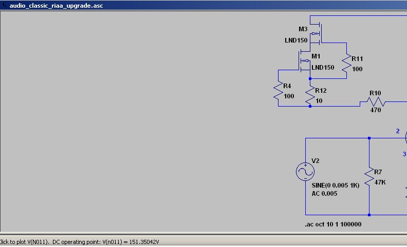
Now I can not go over 151 volt.
.MODEL LND150 VDMOS (Rd=450 VTO=-1.35 Kp=2m Cgdmax=1p Cgdmin=0.25p Cgs=7.5p)
Does not work as intended anymore 🙂
Now I can not go over 151 volt.
How horrible is a ccs made from a single LND150? Surely better than a 150k resistor, no?
See Walt Jung's excellent series of article on current sources on his website -- Walt's Blog 2014 | Walt Jung's 2014 Blog and Info Archive
there is an improved DN2540 current source as well.
Yes, but a single depletion mode MOSFET is still a much stiffer plate load than a resistor, and the cascode LND150 won't work... And the DN2540 cascode won't work well at less than 1 ma, so what's the best compromise solution for a 12AX7 plate load ccs?
A single DN2540 at 1mA should present at least 5Meg up to 2kHz or so. This is just barely enough for a 12AX7. The frequency response will be flat across the audio range, but distortion will begin to creep up above 2kHz (still good though) unless an external load dominates.And the DN2540 cascode won't work well at less than 1 ma, so what's the best compromise solution for a 12AX7 plate load ccs?
If a cascode of about 1mA is desired, one way to increase the Vds of the lower device is this:
Replace the upstairs device with a part that requires more negative Vgs at the operating current. This is easy - the DN2540 will require more than 2V negative in this situation; compare the LND150, which requires almost 0V for the same current.
So try this: DN2540 upstairs, LND150 downstairs.
Replace the upstairs device with a part that requires more negative Vgs at the operating current. This is easy - the DN2540 will require more than 2V negative in this situation; compare the LND150, which requires almost 0V for the same current.
So try this: DN2540 upstairs, LND150 downstairs.
LND150 Cascode CCS
I know Gary must be correct but I thought I had built a cascode LND150 CCS and tested it at 0.8mA.
I built it on a little PCB and tested it with 24V and measured the voltage across a 1K test resistor. Seemed stable at what I thought was 0.8mA.
I put it in circuit to replace the 510K load R on the input cascode of my venerable ol' EAR 859 which runs at about 0.6mA.
With the PCC88 the anode voltages were almost exactly 120V as required (1K cathode bias R) so I thought I was right. Subbing in the fet cascode I had to adjust the current on one side to get the required 120V--I put that down to the greater SS variability.
I know Gary knows his CCSs and must be right so I need to go back and check.
Other than a LND150/DN2540 combo I guess a 3V button cell could be used to give the required voltage for the bottom LND150.
confused Tim
Yes, Tim - the sample-to-sample variability of any FET is wide enough that 0.8mA could easily be possible.
But running the LND150 like that is not optimal - when Vds is very low (as in <0.5V in this case) the temperature stability is degraded, the current-stability is dependent on the upstairs device's actual Vgs, and the effective capacitance is increased.
A cascode formed out of DN2540 and LND150, and given a voltage headroom of say, 25V - will give the lower device nearly 2V of Vds, and low capacitance of the ensemble.
What would be the issue by using a normal enhancement-mode MOSFET on top--say IRF820, gate set by potential-divider via high-value resistor, say 10M and a resistor--say 10-15K to plate, plate to gate via a cap, say 0.1uF...
Output taken from MOSFET to plate resistor node, so has low impedance
Plate volts set by pot-divider, to gate.
Ive used it with 12AX7--Works very well....
Output taken from MOSFET to plate resistor node, so has low impedance
Plate volts set by pot-divider, to gate.
Ive used it with 12AX7--Works very well....
Thanks Rod
Thanks Rod,
Should an IXTP08N100D2 be even better upstairs as that looks to give -3V to bias the LND150?
And I have some of those.
I still like the 3V button cell idea too.
tim
Thanks Rod,
Should an IXTP08N100D2 be even better upstairs as that looks to give -3V to bias the LND150?
And I have some of those.
I still like the 3V button cell idea too.
tim
Hi Tim, Should work very well. The extra bias voltage translates into higher Vds for the downstairs part [LND150] - which reduces its capacitance.
So--Whats the advantage then of using this scheme--over a single enhancement MOSFET then....?
Much less capacitance issues using a single (easy to get) device rather than using two oddballs....
Much less capacitance issues using a single (easy to get) device rather than using two oddballs....
- Status
- Not open for further replies.
- Home
- Amplifiers
- Tubes / Valves
- LND150 gyrator for ECC83/12AX7 ???