Hi.
I wish do make a CCS for my ECC83 Riaa, and I got some help from Rod Coleman who points me in the right direction.
I'm quite new with tubes, but have build a couple of 4P1L pre-amps from this famous thread : http://www.diyaudio.com/forums/tubes-valves/190857-4p1l-dht-line-stage.html
There I use a gyrator DN2540 depletion MosFet in Cascade and I works great.
I have make a LtSpice simulation which seems to work with LND150 and ECC83.
But I have a couple of questions ??
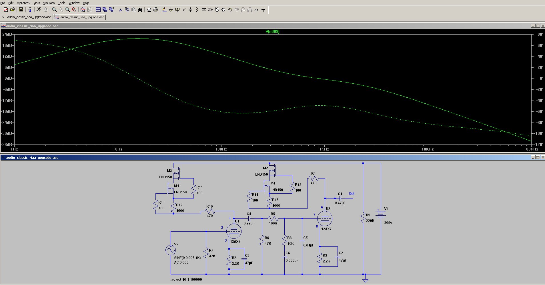
As you can see in this Schematic the RIAA curve is pretty messed up, when I replace the Anode Load (R1 and R4).
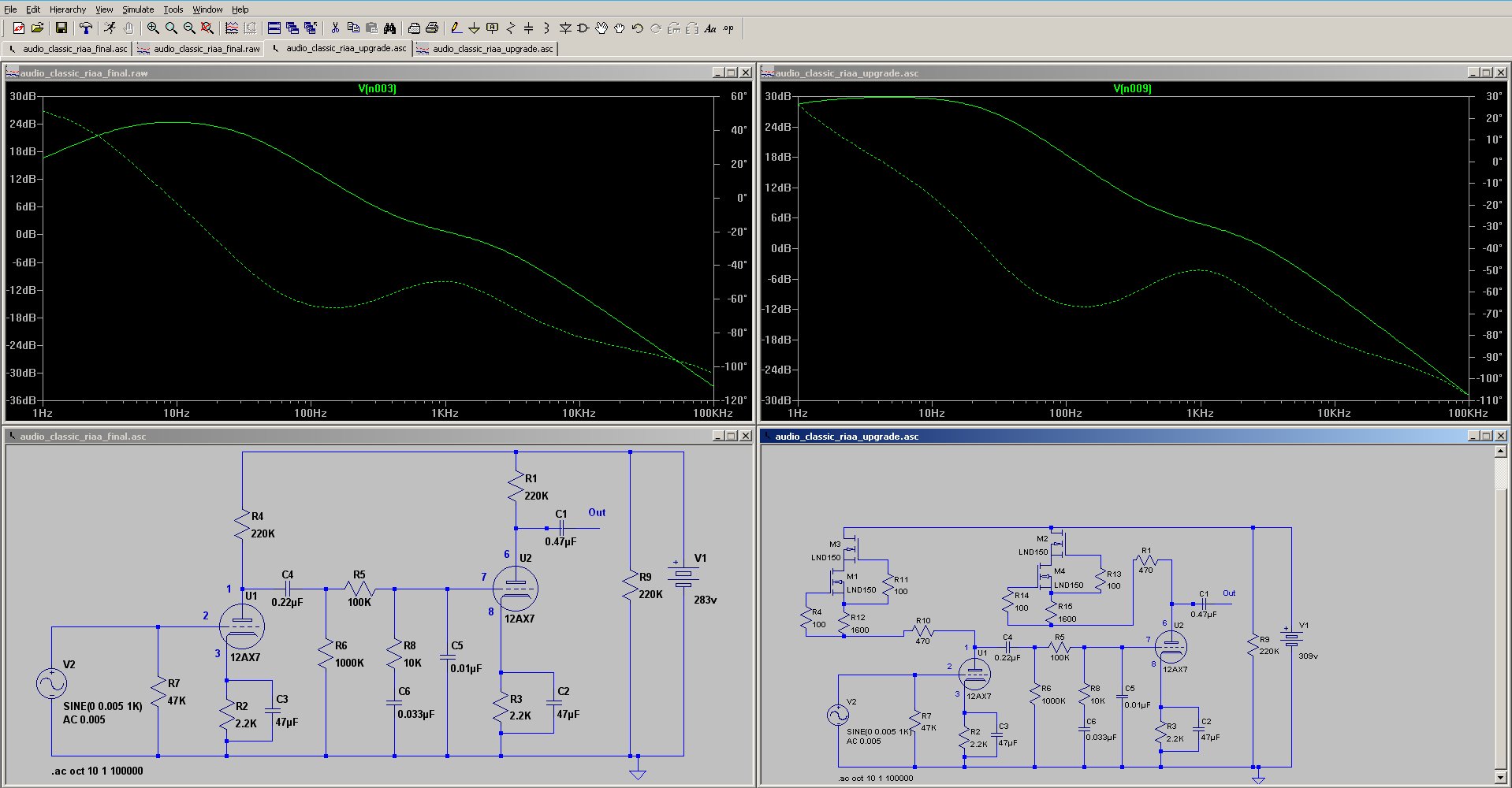
I read something about altering the R6 in the "RIAA network" and when I replace the 1M to a 47K it just seems to be fine again.
Questions ???
1) Is it normal to alter the R6, which seems to work, and any explanations for that ??
2) R4 and R11 and the gyrator I found several using 100R is it okay for LND150, works great on my DN2540 setup ??
3) R12 and R15 is actually adjustable from 1050-2050 which gives me from 125 to 205 volt or ( 0.548 to 0.831 mA ) on the Anode. Saw it on a online schematic is the combination (R4 R11 versus R12) okay ??
4) Plate Load Resistor R10 is quite low now 470R. What is it purpose could it be lowered even further or removed ??
Couldn't fine any answer for these questions therefore this post...
/Thanks Michael.
I wish do make a CCS for my ECC83 Riaa, and I got some help from Rod Coleman who points me in the right direction.
I'm quite new with tubes, but have build a couple of 4P1L pre-amps from this famous thread : http://www.diyaudio.com/forums/tubes-valves/190857-4p1l-dht-line-stage.html
There I use a gyrator DN2540 depletion MosFet in Cascade and I works great.
I have make a LtSpice simulation which seems to work with LND150 and ECC83.
But I have a couple of questions ??
As you can see in this Schematic the RIAA curve is pretty messed up, when I replace the Anode Load (R1 and R4).
I read something about altering the R6 in the "RIAA network" and when I replace the 1M to a 47K it just seems to be fine again.
Questions ???
1) Is it normal to alter the R6, which seems to work, and any explanations for that ??
2) R4 and R11 and the gyrator I found several using 100R is it okay for LND150, works great on my DN2540 setup ??
3) R12 and R15 is actually adjustable from 1050-2050 which gives me from 125 to 205 volt or ( 0.548 to 0.831 mA ) on the Anode. Saw it on a online schematic is the combination (R4 R11 versus R12) okay ??
4) Plate Load Resistor R10 is quite low now 470R. What is it purpose could it be lowered even further or removed ??
Couldn't fine any answer for these questions therefore this post...
/Thanks Michael.
You can use an inverse RIAA block to test frequency-response in LTSpice. I can send, when I get a minute! Using this, you can aim for a flat response, making for easier work.
1. R6 is part of a High-pass filter - to reduce unwanted low frequency signals like LP-warp.
No need to have this too high, unless you have a bad turntable (bearing rumble etc).
3. If you use a very low value of Rs [R12, R15] the LND150 will give about 1mA of current, should be fine for ECC83.
4. R10 is a counter-measure against oscillation. 470R should be fine. It's not a load - this is dominated by the [dynamic] value of impedance of the CCS, which is verry much higher.
Hi Michael,
It's not a gyrator, it is a cascode CCS (constant current source). I use it constantly.
Check anode voltage, anode (CCS) current and cathode bias voltage (on R2 and R3) in the 12AX7 datasheet. This tube is happy at about 150..200V, 0.5...1.2mA operating point (-1....-2V bias).
If you want to test quickly phono schematics in LTSpice use inverse RIAA circuit (oh I see Rod recommend it too 🙂 ).
Attachments
Last edited:
Yes, Michael, Bela's circuit in Post #3 has many advantages over the first schematic - especially the LED cathode biassing, and the ability to drive a cable at the output.
The inverse RIAA block is there too - so you can aim for a flat Freq-response at the output.
The inverse RIAA block is there too - so you can aim for a flat Freq-response at the output.
Hi Michael,
It's not a gyrator, it is a cascode CCS (constant current source). I use it constantly.
Check anode voltage, anode (CCS) current and cathode bias voltage (on R2 and R3) in the 12AX7 datasheet. This tube is happy at about 150..200V, 0.5...1.2mA operating point (-1....-2V bias).
If you want to test quickly phono schematics in LTSpice use inverse RIAA circuit (oh I see Rod recommend it too 🙂 ).
Hi Euro21..
Okay as I said before, now I have questions.
As I can see you're using 1 LND150 pr Anode ??
R3 you set the operating point ??
Why this R4 on top of LND150 ??
The Caps C6 ??
Best Michael.
Yes, Michael, Bela's circuit in Post #3 has many advantages over the first schematic - especially the LED cathode biassing, and the ability to drive a cable at the output.
The inverse RIAA block is there too - so you can aim for a flat Freq-response at the output.
Hi Rod...
I forgot it on my Schematic, I have a 1000K resistor on my output.
These green Led are they just "standard LEDS" ??
Any suggestions ?? I use mouser a lot so a link would be useful..
Hi,As I can see you're using 1 LND150 pr Anode ??
This is cascode LND150 CCS.
I use old (a few ten years old) 5mm round type green LEDs. This type granting (for me) the best tonality (probably due to the low dynamic resistance) in the 1...2mA range (1.7...1.8V residual voltage).
Attachments
Last edited:
Hi Michael,
It's not a gyrator, it is a cascode CCS (constant current source).
Could you please provide the CCS-LND150 and the Cascode CCS sub-circuits?
Could you please provide the CCS-LND150 and the Cascode CCS sub-circuits?
Voilá.
Attachments
Last edited:
Hi Euro21..
on your posted schematic.
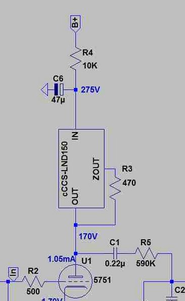
What is the purpose of R4 10K on top of the LND150 ??
I thought it was the point to lower the Resistor as much as possible..
I have 470R after my cascade LND150. But what do i know 🙂
And the C6 47uF ??
on your posted schematic.
What is the purpose of R4 10K on top of the LND150 ??
I thought it was the point to lower the Resistor as much as possible..
I have 470R after my cascade LND150. But what do i know 🙂
And the C6 47uF ??
I'm not able to load that cCCS-LND150.asy into my LTspice schematics. It returns error "Missing schematic(s) of the hierarchy: cccS-lnd150". I know I'm being ignorant and lazy, but can I ask you how to get that to work?
- cCCS-LND150.asy goes into the \sym folder?
- Where does the cCCS-LND150.asc schematic file go? Which folder?
- I didn't see any .inc command in your schematic that points to these LND150 files. Am I missing something?
Thanks.
--
- cCCS-LND150.asy goes into the \sym folder?
- Where does the cCCS-LND150.asc schematic file go? Which folder?
- I didn't see any .inc command in your schematic that points to these LND150 files. Am I missing something?
Thanks.
--
Hi Euro21..
on your posted schematic.
What is the purpose of R4 10K on top of the LND150 ??
I thought it was the point to lower the Resistor as much as possible..
I have 470R after my cascade LND150. But what do i know 🙂
And the C6 47uF ??
That looks like power supply decoupling to me. Just an RC filter to suppress power supply ripple before it gets to the tube's plate. It also reduces the B+ to lighten the load on the CCS. C6 decouples R4 from the tube and its plate load (the LND150 CCS).
--
Last edited:
- cCCS-LND150.asy goes into the \sym folder?
- Where does the cCCS-LND150.asc schematic file go? Which folder?
- I didn't see any .inc command in your schematic that points to these LND150 files. Am I missing something?
--
Hi rongon,
Try to place both (cCCS-LND150.sym and cCCS-LND150.asc) files to the working directory where is the schematic (for example some_phono.asc) file.
If you create own symbol file (something.asy) with same name as it's schematic (something.asc) it will working.
Correct.That looks like power supply decoupling to me. Just an RC filter to suppress power supply ripple before it gets to the tube's plate. It also reduces the B+ to lighten the load on the CCS. C6 decouples R4 from the tube and its plate load (the LND150 CCS).
--
Careful of noise in that first stage. Remember, a 12AX7 will have a high plate resistance, and any current noise from the gyrator will create voltage noise. I found this out the hard way....
Hi rongon,
Try to place both (cCCS-LND150.sym and cCCS-LND150.asc) files to the working directory where is the schematic (for example some_phono.asc) file.
Thank you, that worked great... And thanks for sharing the LND150 CCS circuit.
RG
--
Keep in mind that you won't be able to get much over .4ma from the cascaded version of the LND150 CCS. The lower LND150 won't have enough voltage to operate.
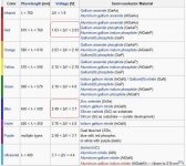
Looking at the saturation characteristics on the data sheet the LND150 needs ~.3V gate to source to get to 1ma output. But, to be functional, it needs a minimum of 1V drain to source to be active.
As the lower LND150's operating voltage is the gate to source voltage set by the upper LND150, ~.3V, the lower LND150 won't have enough voltage to be operating in a linear zone.
Keep in mind that you won't be able to get much over .4ma from the cascaded version of the LND150 CCS. The lower LND150 won't have enough voltage to operate.
Looking at the saturation characteristics on the data sheet the LND150 needs ~.3V gate to source to get to 1ma output. But, to be functional, it needs a minimum of 1V drain to source to be active.
As the lower LND150's operating voltage is the gate to source voltage set by the upper LND150, ~.3V, the lower LND150 won't have enough voltage to be operating in a linear zone.
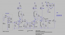
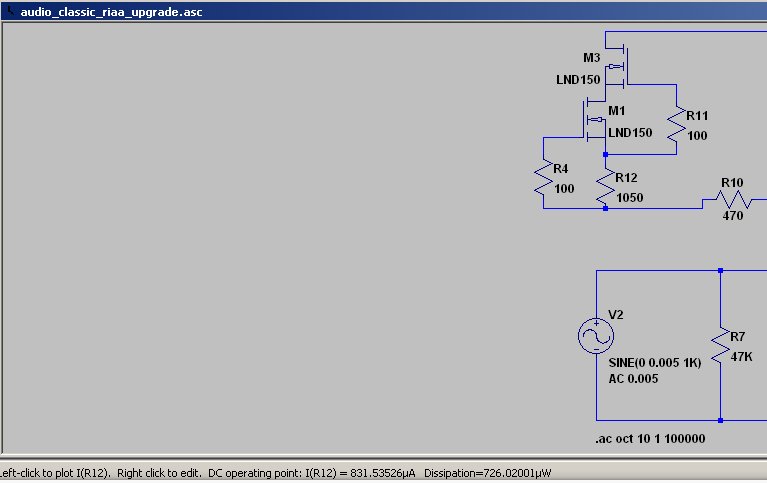
Interesting. This is quite opposite what my Ltspice says. In Ltspice I can have 0.831 mA. See screenshots.
An externally hosted image should be here but it was not working when we last tested it.
Interesting. This is quite opposite what my Ltspice says. In Ltspice I can have 0.831 mA. See screenshots.
The LND150 model is likely faulty, here is the comparison between the model and the datasheet (could be just my model though...):
An externally hosted image should be here but it was not working when we last tested it.
LND150 SPICE model:
Code:
MODEL LND150 NMOS (LEVEL=3 RS=150.00 NSUB=5.0E13 DELTA=0.1 KAPPA=1.O TPG=1 CGDO=2.1716E-12 RD=40.0 VTO=-2.0 VMAX=1.0E8 ETA=0.1 NFS=6.6E10 TOX=1.0E-7 LD=1.698E-9 UO=862.425 XJ=6.4666E-7 THETA=1.0E-5 CGSO=5.09E-10 L=10.0E-6 W=600E-6)
Last edited:
- Status
- Not open for further replies.
- Home
- Amplifiers
- Tubes / Valves
- LND150 gyrator for ECC83/12AX7 ???