Bit of a first thread here.
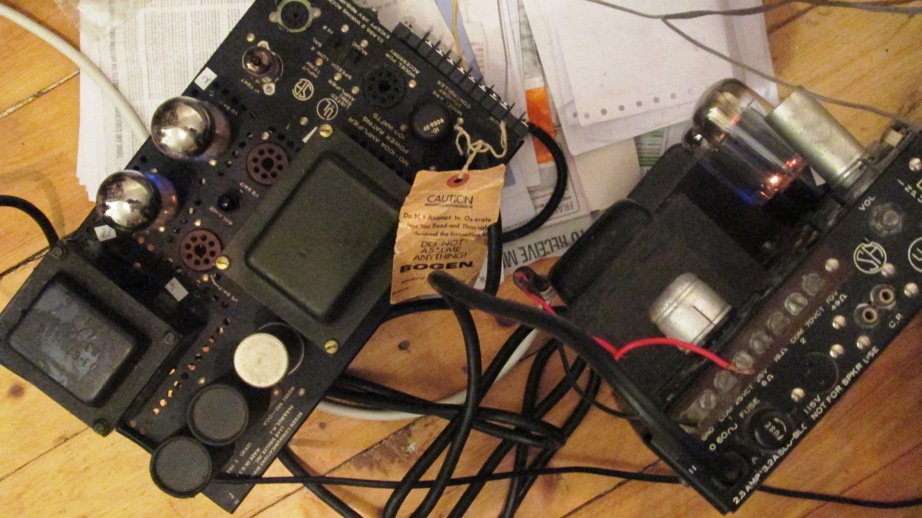
I got a pair of Bogen MO100A amps finally.
TWO monobloc 100W amps is as good as ONE modified MO200 (stereo) after all....
I dunno if another MO100A thread is going to resurrect, being as the main craze is to junk the good low impedance OP valves and fill it up with Mullard junk.
The MO100/200 are the last cheap valve amp out there, now the "philes" are going crazy, paying stupid prices, and the "flippers" have latched on to getting stupid money for dirty, worn out, incomplete old pre-THX cinema/theatre PA systems on Ebay.
It took forever to find the 2nd MO100A, so the single one I had lingered in a corner for years.
After the other one of the pair got sent from the USA at christmas, the serious testing and tweaking started.
I could explain the various problems encountered on the way.
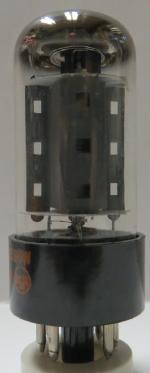
Most of them come from the rather weak driver situation rather than the 8417 valves, which with the excellent output transformers turned out to be the strong end.
The first smart thing was to run them direct on 220/230V.
Being as they were imported direct from the USA, that involved wiring the HT/Power transformers for the 2 amps in series, then removing a pair each of the 8417 and running them with only ONE pair per amp.
That all worked a treat.
Then started the fun and games!
I got a pair of Bogen MO100A amps finally.
TWO monobloc 100W amps is as good as ONE modified MO200 (stereo) after all....
I dunno if another MO100A thread is going to resurrect, being as the main craze is to junk the good low impedance OP valves and fill it up with Mullard junk.
The MO100/200 are the last cheap valve amp out there, now the "philes" are going crazy, paying stupid prices, and the "flippers" have latched on to getting stupid money for dirty, worn out, incomplete old pre-THX cinema/theatre PA systems on Ebay.
It took forever to find the 2nd MO100A, so the single one I had lingered in a corner for years.
After the other one of the pair got sent from the USA at christmas, the serious testing and tweaking started.
I could explain the various problems encountered on the way.
Most of them come from the rather weak driver situation rather than the 8417 valves, which with the excellent output transformers turned out to be the strong end.
The first smart thing was to run them direct on 220/230V.
Being as they were imported direct from the USA, that involved wiring the HT/Power transformers for the 2 amps in series, then removing a pair each of the 8417 and running them with only ONE pair per amp.
That all worked a treat.
Then started the fun and games!
"The first smart thing was to run them direct on 220/230V.
Being as they were imported direct from the USA, that involved wiring the HT/Power transformers for the 2 amps in series, then removing a pair each of the 8417 and running them with only ONE pair per amp."
How is that stable? If you wire a pair of 12v lamps, of identical wattage, in series across a 24v supply, they will work. If you vary the wattage on one, the lamp that draws the least power will have too much voltage on it and then will age very quickly.
If you wire a pair of 12v lamps, of identical wattage, in series across a 24v supply, they will work. If you vary the wattage on one, the lamp that draws the least power will have too much voltage on it and then will age very quickly.
ahum do you have idea what you are talking about?
What is the average efficiency of a valve amp, including the heaters inc all the gross inefficiencies of the system & the large quiescent current drain of the output stage?
The system is blowing 60W doing nothing at all just in the output valves alone!
Even if you were to run just ONE channel flat out, & the other one with no output it would hardly add up to much difference in total current drain at 220V....hence the total tosh of all these stupid MAINS CONDITIONER and "HI END" power cables.
Anyway, back to the task of modifying these amps.
They can sound pretty good actually, as I rapidly found out.
I loved the original paper label that came with it:- "do not assume anything".
I didn't expect to, because I already had one working one before.
There's a number of threads on the internet about these units mostly on the Audioasylum & Audiokarma web sites & another one on here about modifying the paralleled up MO100A, the MO200A.
Lots of useful stuff came out of this, especially some details about the MO200A OPT which don't really interest me here, because I don't have those problems using 2 identical monoblocs.
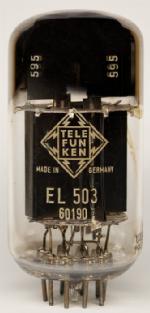
In any case with 650V of HT & valves able to dump up to 1/4 of an amp, that adds up to a thoroughly modern way of working "a la" EL503 which are quite similar in many ways...
It's why they, like the 8417, were some of the last valves made, in a last ditch production attempt to compete with the TO3 package power transistor....so found its way into Bogen, Dynaco VI
Both the EL503 (1963) , 7591 (1960), 8417 (1961-1988) date from the early 60s, the time of the arrival of the pencil valves, ICBMs, missile guidance, compactrons and all sorts of other weird stuff.
The 6111, 6112 pencil double triodes are also brilliant, which is why temporarily I wired one into 1 channel until I could think of a new solution to the driver hassles..
High gain, low impedance valves = low drive distortion,- bit like a MOSFET.
It always strikes me you have to get valid test sequences before and after, not just what scopes and volt meters tell you.
This is the empirical approach which comes from professional audio, not from the "audiophile" freaks end, which usually sounds terrible, vetted and policed by a community that couldn't double blind test anything because their hearing invariably stops at 8-10khz.
How they can claim to hear the influence of changing any valve or wire or coupling capacitor, or cryo this or that, beats me, but they do.
In a professional studio environment you are double blind testing everything, when you are vetting & controlling a colleague's work, especially with coincident microphones techniques, but I digress...It's another subject.
Here's the thread and what was done 2-3yrs ago on these amps which was both a transplant and a conversion:-
http://www.diyaudio.com/forums/tubes-valves/218962-bogen-mo-200a-transplant-conversion.html
The interesting point about most of the thread is again how each time they were so keen to replace the output valves with 6550 or EL34, both of which have far less gain and needed much heavier negative bias as a result.
This inevitably ends up in further driver trouble, as the original amplifier has very low sensitivity anyway.
I found driving with it with a 0dB line level from proper professional studio sound cards, the original amplifier couldn't get near a decent output*.
Being as the original 8417 runs only about -15V (so 30V pk-pk) to get full output, moving to 6550 entails moving the negative supply down to about -40V so needs AT LEAST DOUBLE the drive.
The 6DW7 (12AU7) original phase invertor is "just about" able to struggle enough drive for the 8417, but does this at the cost of loss linearity, and losing near 1/2 it's AC signal into the low impedance valve bias circuit.
This is of course preceded by the other half of that valve (based on 12AX7) which suffers from exactly the same problem with a shed load of hum and noise added for good measure.
For a PA amp,(or maybe several paralleled up in a cinema) it's fine, but hi-fi it is not.
I reckon on tests, it's why the Bogen amp scores well at low frequencies but has pretty poor performance on high frequency THD and roll off as delivered.
(* I don't use any of these bespoke DAC or other consumer products, most of the sources come straight out of a digigram PCMCIA or Lynx studio sound card, which in my opinion have much better convertors than most and run native 24-96 24bit, which we record in. All is XLR based, balanced stuff.
Good stuff in=good stuff out, and no vinyl to be seen anywhere near!)
I didn't want to change the output stage, because the 8417 is a low impedance high voltage device.
It's unlikely to improve upon using the KT88, and they are in any case far too big to fit into that space.
EL34 is a non starter again because of the drive requirements, the very poor quality of that valve (1st prod 1954) & the heavy G2 emission, from as long ago as the treacherous Philips-Mullard who forced the world to adopt a valve that routinely melts.
Here's some of the other links to round it all up:-
Bopgen MO100A phase inverter for 6550's - AudioKarma.org Home Audio Stereo Discussion Forums
bogen MO100a monoblocks overhaul - AudioKarma.org Home Audio Stereo Discussion Forums
Bogen mo100a tube replacement - AudioKarma.org Home Audio Stereo Discussion Forums
https://community.klipsch.com/index.php?/topic/65409-resistors-are-futile/
Tube DIY Asylum
Hope it makes a good read.
Here's some photos from the first days when they got assembled.
The first hours were spent messing about with all kinds of things inc calibration of the whole system with Neumann microphones and all...days and days of tests and adjustments!
At least the first tests proved this was all in the right direction, a 1khz sine wave out came back as a 1khz sine recorded from the speakers.
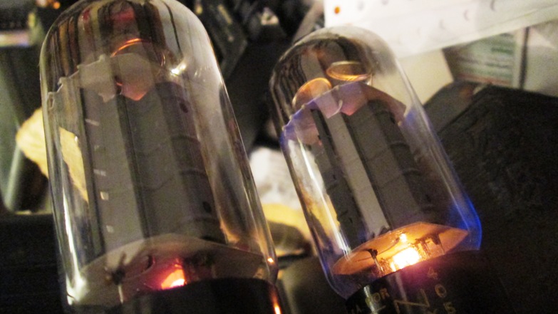
A nice glow:-
They can sound pretty good actually, as I rapidly found out.
I loved the original paper label that came with it:- "do not assume anything".
I didn't expect to, because I already had one working one before.
There's a number of threads on the internet about these units mostly on the Audioasylum & Audiokarma web sites & another one on here about modifying the paralleled up MO100A, the MO200A.
Lots of useful stuff came out of this, especially some details about the MO200A OPT which don't really interest me here, because I don't have those problems using 2 identical monoblocs.
In any case with 650V of HT & valves able to dump up to 1/4 of an amp, that adds up to a thoroughly modern way of working "a la" EL503 which are quite similar in many ways...
It's why they, like the 8417, were some of the last valves made, in a last ditch production attempt to compete with the TO3 package power transistor....so found its way into Bogen, Dynaco VI
Both the EL503 (1963) , 7591 (1960), 8417 (1961-1988) date from the early 60s, the time of the arrival of the pencil valves, ICBMs, missile guidance, compactrons and all sorts of other weird stuff.
The 6111, 6112 pencil double triodes are also brilliant, which is why temporarily I wired one into 1 channel until I could think of a new solution to the driver hassles..
High gain, low impedance valves = low drive distortion,- bit like a MOSFET.
It always strikes me you have to get valid test sequences before and after, not just what scopes and volt meters tell you.
This is the empirical approach which comes from professional audio, not from the "audiophile" freaks end, which usually sounds terrible, vetted and policed by a community that couldn't double blind test anything because their hearing invariably stops at 8-10khz.
How they can claim to hear the influence of changing any valve or wire or coupling capacitor, or cryo this or that, beats me, but they do.
In a professional studio environment you are double blind testing everything, when you are vetting & controlling a colleague's work, especially with coincident microphones techniques, but I digress...It's another subject.
Here's the thread and what was done 2-3yrs ago on these amps which was both a transplant and a conversion:-
http://www.diyaudio.com/forums/tubes-valves/218962-bogen-mo-200a-transplant-conversion.html
The interesting point about most of the thread is again how each time they were so keen to replace the output valves with 6550 or EL34, both of which have far less gain and needed much heavier negative bias as a result.
This inevitably ends up in further driver trouble, as the original amplifier has very low sensitivity anyway.
I found driving with it with a 0dB line level from proper professional studio sound cards, the original amplifier couldn't get near a decent output*.
Being as the original 8417 runs only about -15V (so 30V pk-pk) to get full output, moving to 6550 entails moving the negative supply down to about -40V so needs AT LEAST DOUBLE the drive.
The 6DW7 (12AU7) original phase invertor is "just about" able to struggle enough drive for the 8417, but does this at the cost of loss linearity, and losing near 1/2 it's AC signal into the low impedance valve bias circuit.
This is of course preceded by the other half of that valve (based on 12AX7) which suffers from exactly the same problem with a shed load of hum and noise added for good measure.
For a PA amp,(or maybe several paralleled up in a cinema) it's fine, but hi-fi it is not.
I reckon on tests, it's why the Bogen amp scores well at low frequencies but has pretty poor performance on high frequency THD and roll off as delivered.
(* I don't use any of these bespoke DAC or other consumer products, most of the sources come straight out of a digigram PCMCIA or Lynx studio sound card, which in my opinion have much better convertors than most and run native 24-96 24bit, which we record in. All is XLR based, balanced stuff.
Good stuff in=good stuff out, and no vinyl to be seen anywhere near!)
I didn't want to change the output stage, because the 8417 is a low impedance high voltage device.
It's unlikely to improve upon using the KT88, and they are in any case far too big to fit into that space.
EL34 is a non starter again because of the drive requirements, the very poor quality of that valve (1st prod 1954) & the heavy G2 emission, from as long ago as the treacherous Philips-Mullard who forced the world to adopt a valve that routinely melts.
Here's some of the other links to round it all up:-
Bopgen MO100A phase inverter for 6550's - AudioKarma.org Home Audio Stereo Discussion Forums
bogen MO100a monoblocks overhaul - AudioKarma.org Home Audio Stereo Discussion Forums
Bogen mo100a tube replacement - AudioKarma.org Home Audio Stereo Discussion Forums
https://community.klipsch.com/index.php?/topic/65409-resistors-are-futile/
Tube DIY Asylum
Hope it makes a good read.
Here's some photos from the first days when they got assembled.
The first hours were spent messing about with all kinds of things inc calibration of the whole system with Neumann microphones and all...days and days of tests and adjustments!
At least the first tests proved this was all in the right direction, a 1khz sine wave out came back as a 1khz sine recorded from the speakers.
A nice glow:-
More progress this week.
It consisted of spending countless hours trying to look up and compare lots of more or less unobtainable info with a few jokers appearing....
The main thrust of all the effort of course is to dump this 12DW7/7247 valve.
To summarise:-
The 7247 is 1/2 a 12AU7 (phase splitter) and 1/2 a 12AX7 (high gain amp)
My first tweak (being short of ONE 7247 valve at the time) was to rip out the original circuitry from one channel and replace the 7247 with a new 12AU7, I had lurking around, while at the same time check how much the distortion/noise levels might change.
That meant disconnecting all the stuff from what was supposed to be the hi gain amp section and discretely wiring a 6112 in the place of that.
This correspondingly dropped the gain as expected, but here is what actually happened...
The tiny 6112 submin valve has a very rigid internal structure and is supposed to run on about 170V max.
According to Bogen, the original 7247 (12AX7 section) input valve only has about 60V on the anode, from a 260V supply, with a 470k Rl and Rk of 1.2K.
Clearly the valve is scarcely conducting at this value, doing all of about 0.4m/a with a cathode bias of about 0.5V.
This is really outside of the proper operating area of the valve & quite non linear.
What happened in a cinema with a nice bit of drive I hate to imagine, but probably only worked because they stuck maybe 3-4 of the amps in parallel then through some 70V line transformers (?!)
It sounds bad? Oh well, bigger is better eh, let's add some more monoblocs.
No wonder the Bogen reps said they didn't sound great!
I'm not at all sure why they did all this, making a plate impedance tending towards 100k, a gain of only about 35, & such low conduction but it would explain some of the more gross distortion and the fact it could scarcely generate more than about 5-7V o/p before clipping.
I swopped the Ra for 100k this brings the anode up to more like 150V.
This is far more in the right area for this valve, swopped RK for 2k2, so more like 1m/a going thru it.
The cathode bias will be in the right area at 2V.
The gain made an immediate jump with obviously lower distortion.
Here the valve is more likely to have a Mu of 100 and a stage gain of 50.
Anode impedance drops by nearly 1/2 too, so that's the virtuous curve kicking in all over.
This was all dutifully copied over to ONE side of my little 6112, which of course is fine at Va of 150V.
It's a real nasty, soldering to any 611x wire ended triode so I used chopped IC sockets to push onto the wires and solder to them instead.
Looks messy, but who cares, it's not staying for long like that.
It all worked fine. (The 6112 has a Mu of 70, so that channel now has little less gain), but that was a temporary fix to get some handle on what is really not right on this amp, and be able to compare the 2 tweaked channels against each other.
The 2 channels in any case, each have individual gain controls.
6112 data typically quotes a gain of 50 at 1m/a with 0.9% THD at 5V out, which has got to be better than what was there before.
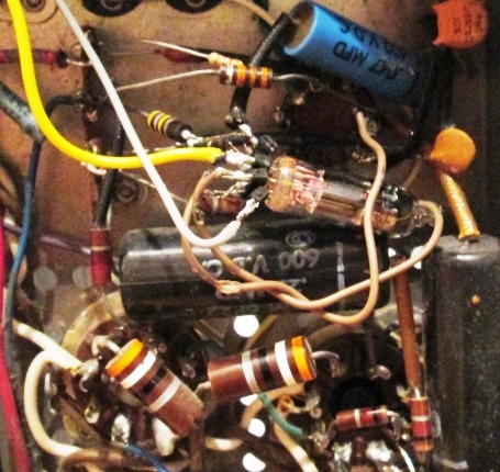
Here's a photo.
When is an extra valve not an extra valve? When it's hiding underneath!
It gets quite hot, but it says the plate can handle 0.55W in a missile.
This tweak cost peanuts and the amplifier is unrecognisably better.
Being as we have released quite a lot of spare current capacity on the HT & filament, power supply thanks to removing the 2, 8417s in each amp, I can now attend to the next big tweak consists of dumping the 7247 valve in the other channel and cleaning them both up properly
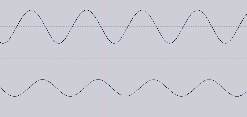
This curve looks pretty nice to me, considering the Neumann KM microphone measuring has a known roll off below 100hz.
(I have the curves for them and they matched exactly against the B +K).
It consisted of spending countless hours trying to look up and compare lots of more or less unobtainable info with a few jokers appearing....
The main thrust of all the effort of course is to dump this 12DW7/7247 valve.
To summarise:-
The 7247 is 1/2 a 12AU7 (phase splitter) and 1/2 a 12AX7 (high gain amp)
My first tweak (being short of ONE 7247 valve at the time) was to rip out the original circuitry from one channel and replace the 7247 with a new 12AU7, I had lurking around, while at the same time check how much the distortion/noise levels might change.
That meant disconnecting all the stuff from what was supposed to be the hi gain amp section and discretely wiring a 6112 in the place of that.
This correspondingly dropped the gain as expected, but here is what actually happened...
The tiny 6112 submin valve has a very rigid internal structure and is supposed to run on about 170V max.
According to Bogen, the original 7247 (12AX7 section) input valve only has about 60V on the anode, from a 260V supply, with a 470k Rl and Rk of 1.2K.
Clearly the valve is scarcely conducting at this value, doing all of about 0.4m/a with a cathode bias of about 0.5V.
This is really outside of the proper operating area of the valve & quite non linear.
What happened in a cinema with a nice bit of drive I hate to imagine, but probably only worked because they stuck maybe 3-4 of the amps in parallel then through some 70V line transformers (?!)
It sounds bad? Oh well, bigger is better eh, let's add some more monoblocs.
No wonder the Bogen reps said they didn't sound great!
I'm not at all sure why they did all this, making a plate impedance tending towards 100k, a gain of only about 35, & such low conduction but it would explain some of the more gross distortion and the fact it could scarcely generate more than about 5-7V o/p before clipping.
I swopped the Ra for 100k this brings the anode up to more like 150V.
This is far more in the right area for this valve, swopped RK for 2k2, so more like 1m/a going thru it.
The cathode bias will be in the right area at 2V.
The gain made an immediate jump with obviously lower distortion.
Here the valve is more likely to have a Mu of 100 and a stage gain of 50.
Anode impedance drops by nearly 1/2 too, so that's the virtuous curve kicking in all over.
This was all dutifully copied over to ONE side of my little 6112, which of course is fine at Va of 150V.
It's a real nasty, soldering to any 611x wire ended triode so I used chopped IC sockets to push onto the wires and solder to them instead.
Looks messy, but who cares, it's not staying for long like that.
It all worked fine. (The 6112 has a Mu of 70, so that channel now has little less gain), but that was a temporary fix to get some handle on what is really not right on this amp, and be able to compare the 2 tweaked channels against each other.
The 2 channels in any case, each have individual gain controls.
6112 data typically quotes a gain of 50 at 1m/a with 0.9% THD at 5V out, which has got to be better than what was there before.
Here's a photo.
When is an extra valve not an extra valve? When it's hiding underneath!
It gets quite hot, but it says the plate can handle 0.55W in a missile.
This tweak cost peanuts and the amplifier is unrecognisably better.
Being as we have released quite a lot of spare current capacity on the HT & filament, power supply thanks to removing the 2, 8417s in each amp, I can now attend to the next big tweak consists of dumping the 7247 valve in the other channel and cleaning them both up properly
This curve looks pretty nice to me, considering the Neumann KM microphone measuring has a known roll off below 100hz.
(I have the curves for them and they matched exactly against the B +K).
I spent the best part of 2 1/2 days into the early hours looking up valve specs, curves,old stocks, and goodness knows what before embarking on ordering bits, then getting out the soldering iron again (next week with any luck!).
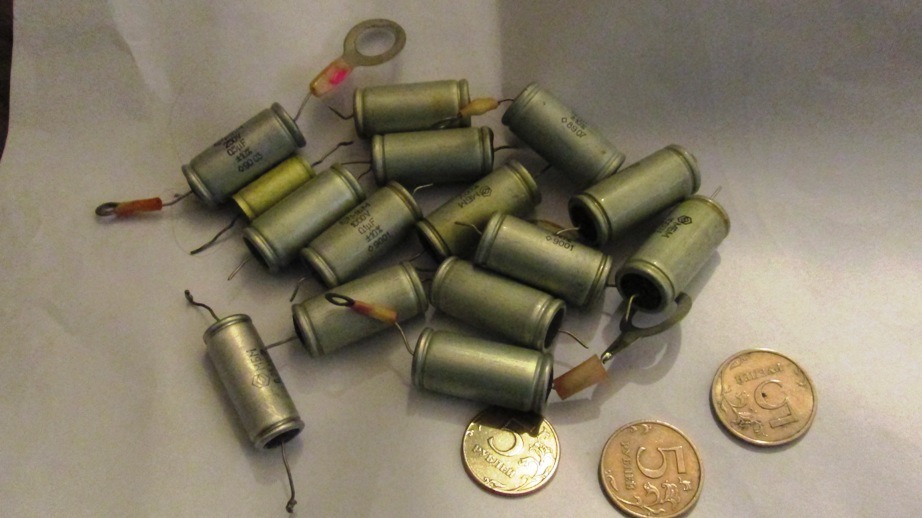
The handy thing about Russia is the element of suprise.
Go into the local sparky shop and by the door was a box of junk for 1 rouble a piece.
This of course stands for Конденсаторы металлобумажные...(MBM), some of them up 1000v rated, just perfect for the job in hand...
I am shocked to see greedy people in the west are selling these for up to a DOLLAR a shot on Ebay.
I just filled up a plastic bag and paid 50x less at the counter, all unused but some with short leads and tags soldered on.
Next tricks is going to be ordering some proper driver valves for the Bogen amp.
If you run them in series, the closer to Class A they are the more evenly balanced their load will be. Consider a full bridge instead of the doubler and run from the same B+ as the drivers currently run.
Then consider a more capable front end. An LTP of small power pentodes with Schade FB( local) is not to be despised...
cheers,
Douglas
Then consider a more capable front end. An LTP of small power pentodes with Schade FB( local) is not to be despised...
cheers,
Douglas
I wasn't sure quite what all that meant.
The output valves are never going to be anything but close to AB2 in that setup.
I was just coming to the front end, and explain how it took such a long time to get the right info and a decision (power output valve run as a triode) for the phase splitter/driver.
Principal object of course all along is to keep everything low impedance and low distortion.
A very good point, I looked at your link, and funnily enough it was exactly what I was about to do with a pentode. (shock horror!)
There are several points about the existing amplifier which make the LTP a no-go.
The balance problems simply get a lot worse, when the output valves have very high gain and low drive requirements.
As a proportion of total,- 200mV of mismatch at 10-15V drive is very different from 200mV at say the drive requirements of a 1930s valve (like the 807 needing 60-80V of drive).
Unfortunately most of the valve thinking from the Chinks is still based around 1930s valve tech, and how to cram as many Shuan-bang EL34 or KT88 clones into a space where the mains transformer can't go up in smoke.
The tolerances in dual driver tubes simply stack up badly, because they are simply never exactly the same.
As a result the "tube rolling" boys are all filling up the pages of the interweb, with the sonic nonsenses of "sound stages", "bright uppers" (WTF!), I give up!
They really are getting high on their 400$ 'funken this or 'vania that, pursued by a team of traders, with their wild claims and tube-vana "multiply by x100 prices", while the speakers are still not capable of even the resolution of a Sony DAT recorder of yester-year.
(I have a few of those and even the DAC are good quality).
There's a whole life to be wasted with such things.
You could buy a Steinway model D, and pay someone to play it in your front room, with the amount of dosh & time those people are wasting, swopping, playing, while suspending their 2000$ speaker cables on little dominos...
Hilarious!
It's like watching people on the TV tasting wines, complete with the "Oooooh...and aaahh"..."that's nice",when you know full well you'll never find that brand or vintage on your local supermarket shelf.
I digress!
The 8417 was as I mentioned in a class of valve more typical of 1960s TV scan/frame tubes, ie. low impedance devices a bit more resembling a FET.
They carried on trying to compete with the transistor, then had to give up completely with the 1970-80s FET.
I wanted to go a different route here.
I got to work, trying to download & check just about every single triode connected pentode you can find that will fit in that little noval socket, without having to add any circuit boards, and trying to make it "look" as though nothing had ever happened.
Fortunately some clever people have done the hard work and it's worth it.
I'm afraid rules out the Mosfet, the design link I thank you for.
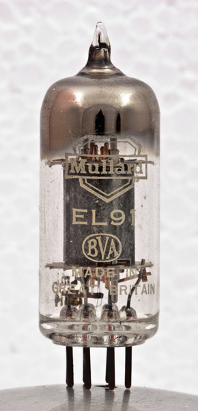
It's becoming a real cliche to talk about stuff "on steroids" but what is going in there instead, is what is still regarded as the WORST valves that Mullard ever made.
"on steroids"
Anyone who has ever had to endure the sound and video of 405line B+W TV followed by its 525 line sister will know exactly what I'm on about.
You got a big book or banged the top of the telly, when the tuning went awol or when yet another of those infernal valves got a bad contact somewhere inside.
Having all the heaters in series, across a mains supply that changed voltage anything from 255v - 225v when the 9 o'clock news came on, was bound to show some weird and wonderful anomalies, never mind the test flights of Concorde which we had to endure every 10 mins which turned VHF/UHF telly as well as FM stereo into a grand radar set.
I'll stop here to pause for breath, and tried to explain why the ECL-PCL-UCL series of audio valves got a stinking reputation in the 60s, and why the invention of the transistor was such a huge relief!
Here, it appear the UCL/ECL series is simply going to be THE BIZ!
Here a flight down nostalgia alley from our local friend.
Don't knock the technology!
There are the solid state and tube soldiers who can't see the big picture.
Every decade reaches a pinnacle of a known technology.
The Americans with their NASA and moon landings based on 1940s German V2s, still haven't rivalled our European SST complete with "fly by wire" from the 60s.
(The Russians weren't even capable of making their SST clone fly reliably at all.. )
Funnily enough. all this was about the same time, radio valves also reached their apex of development and stereo became popular, thanks to DECCA.
Sure as anything, we couldn't do any of that ever again.
There are several points about the existing amplifier which make the LTP a no-go.
The balance problems simply get a lot worse, when the output valves have very high gain and low drive requirements.
As a proportion of total,- 200mV of mismatch at 10-15V drive is very different from 200mV at say the drive requirements of a 1930s valve (like the 807 needing 60-80V of drive).
Unfortunately most of the valve thinking from the Chinks is still based around 1930s valve tech, and how to cram as many Shuan-bang EL34 or KT88 clones into a space where the mains transformer can't go up in smoke.
The tolerances in dual driver tubes simply stack up badly, because they are simply never exactly the same.
As a result the "tube rolling" boys are all filling up the pages of the interweb, with the sonic nonsenses of "sound stages", "bright uppers" (WTF!), I give up!
They really are getting high on their 400$ 'funken this or 'vania that, pursued by a team of traders, with their wild claims and tube-vana "multiply by x100 prices", while the speakers are still not capable of even the resolution of a Sony DAT recorder of yester-year.
(I have a few of those and even the DAC are good quality).
There's a whole life to be wasted with such things.
You could buy a Steinway model D, and pay someone to play it in your front room, with the amount of dosh & time those people are wasting, swopping, playing, while suspending their 2000$ speaker cables on little dominos...
Hilarious!
It's like watching people on the TV tasting wines, complete with the "Oooooh...and aaahh"..."that's nice",when you know full well you'll never find that brand or vintage on your local supermarket shelf.
I digress!
The 8417 was as I mentioned in a class of valve more typical of 1960s TV scan/frame tubes, ie. low impedance devices a bit more resembling a FET.
They carried on trying to compete with the transistor, then had to give up completely with the 1970-80s FET.
I wanted to go a different route here.
I got to work, trying to download & check just about every single triode connected pentode you can find that will fit in that little noval socket, without having to add any circuit boards, and trying to make it "look" as though nothing had ever happened.
Fortunately some clever people have done the hard work and it's worth it.
I'm afraid rules out the Mosfet, the design link I thank you for.
It's becoming a real cliche to talk about stuff "on steroids" but what is going in there instead, is what is still regarded as the WORST valves that Mullard ever made.
"on steroids"
Anyone who has ever had to endure the sound and video of 405line B+W TV followed by its 525 line sister will know exactly what I'm on about.
You got a big book or banged the top of the telly, when the tuning went awol or when yet another of those infernal valves got a bad contact somewhere inside.
Having all the heaters in series, across a mains supply that changed voltage anything from 255v - 225v when the 9 o'clock news came on, was bound to show some weird and wonderful anomalies, never mind the test flights of Concorde which we had to endure every 10 mins which turned VHF/UHF telly as well as FM stereo into a grand radar set.
I'll stop here to pause for breath, and tried to explain why the ECL-PCL-UCL series of audio valves got a stinking reputation in the 60s, and why the invention of the transistor was such a huge relief!
Here, it appear the UCL/ECL series is simply going to be THE BIZ!
Here a flight down nostalgia alley from our local friend.
Don't knock the technology!
There are the solid state and tube soldiers who can't see the big picture.
Every decade reaches a pinnacle of a known technology.
The Americans with their NASA and moon landings based on 1940s German V2s, still haven't rivalled our European SST complete with "fly by wire" from the 60s.
(The Russians weren't even capable of making their SST clone fly reliably at all.. )
Funnily enough. all this was about the same time, radio valves also reached their apex of development and stereo became popular, thanks to DECCA.
Sure as anything, we couldn't do any of that ever again.
An externally hosted image should be here but it was not working when we last tested it.
Fortunately Mr Millett has done a lot of the hard work for us...
It really does date from more than a decade ago:-
Audio Asylum Thread Printer
This guy adds a bit of convincing explanation:-
The Solid State Tube
here too:-
Valve Technology
Triode strapped pentode low distortion split load invertors (concertina) therefore produce extremely low distortion,- mostly 2nd harmonic and this will cancel out in the final stage also.
For those not so familiar with the basic ideas (there are some here) here is a good comparison:-
Valve Technology - A Practical Guide
The theme keeps coming back:-
http://www.diyaudio.com/forums/tubes-valves/165221-most-linear-triode-strapped-pentode-8.html
& here:-
http://www.diyaudio.com/forums/tubes-valves/117158-triode-versus-pentode.html
And another favourite again from Millett where he goes for a pentode driver:-
813 SE triode amps
Finally the really good stuff he posted from:-
High Gm driver pentodes
and another invaluable one:-
http://www.4tubes.com/DATASHEETS/Overviews/Overview-pentodes-in-Triode-Mode.pdf
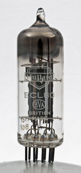
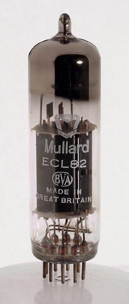
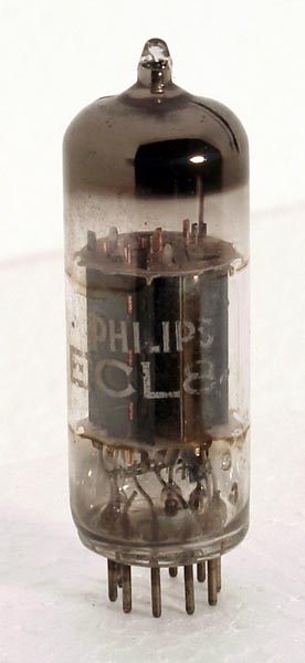
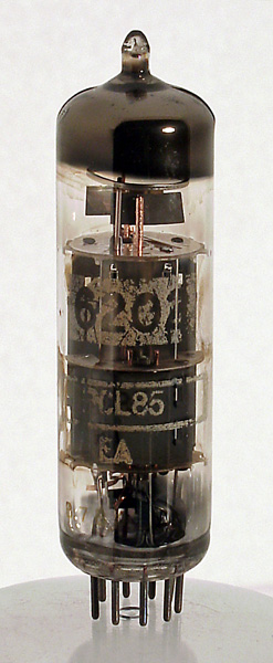
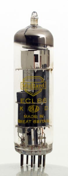
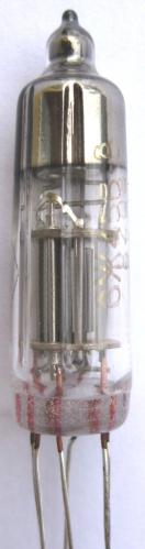
In the end after going through ALL the ECL variants from 80 to 86 plus some ELL stuff, the choice fell on only ONE possible valve in that spot, partly also because of the extreme compact package which is the same as the 7247.
Indications are a likely distortion level below 0.1% at 10-15V of output low Mu (9.4) and typically 25m/a Ik, about 2-3x what you will ever get from any small signal triode, so low low impedance....
The ECL80, ECL82, ECL84 ECL85 & ECL86 were all rejected for different reasons.
Remember how those horrible B+W telly sounded and the "dansette" lead weight pickup arms on the portable vinyl disk players for 60s picnics, or the AC mains powered bakelite radios with all the heaters in series and a live chassis?
Why did they sound so awful, with masses of hum and distortion?
(Well they typically struggled out a nasty overheating 3-8W with 10% THD!)
They must have been designed on a beer mat.
Working out what on earth is really inside the budget valves of course is a whole story of tea, late nights and Sherlock Holmes...
Did they suffer from terrible quality control or was it just the marketing dept, got it wrong and stuck them all in the wrong places?

For a start, the ECL83 is NOT the same as the PCL83, which is somewhat stupid.
The ECL83 has a high mu triode, the equivalent of which I literally can find nowhere..it;s somewhere between a 12AT7/5691 and a 12AX7 up at 83-85.
The 12V filament version (PCL83) has a triode which is a 12AU7/ECC82.
(Mu 17-19). This is not so hard to find out & takes 0.3A
Being as the filament isn't even centre tapped that means rewiring the 7247 socket which is...and now it will take 0.6A instead.
When we look at the UCL83 it reverts to the design of the ECL83 but with a 38-40v 0.1A heater.

Actually Bogen should have run the old 7247 heater at more like 60V off ground to be correct but they didn't bother, choosing to have this large potential difference internally right across the whole thing on AC.
+
The main problem as mentioned before, -the AU section of the 7247 is driving an AC load of only about 22k with Ra of about 33k from 200V.
That's a sure way to lose about half your signal before you start....
Maybe the smart way would be to put a UCL 83 in there finally, stack the heaters of both sections up at about 100V and use the hi mu triode as the upper part of a cascode adventure in the input section....with a 5719/6948 sub min (mu70) wired in there at the bottom of the cascode D-C amp to the triode strapped pentode...
I could even use a 5840/EF732 submin pentode as these are really good, and used in condensor mics already as a sub for the old AC701K so they can't be bad eh?
A weeny little transformer (5VA) rectified to DC for +/- 40V would do the whole Bogen 100A wonders for DC bias (with a 7915 reg for the 8417) as well as provide nice quiet input filaments for everything....costs peanuts.
The pentode bit I will get around to in a minute.
It needs to make some serious current and run it off a proper supply of 300V+
It really does date from more than a decade ago:-
Audio Asylum Thread Printer
This guy adds a bit of convincing explanation:-
The Solid State Tube
here too:-
Valve Technology
Triode strapped pentode low distortion split load invertors (concertina) therefore produce extremely low distortion,- mostly 2nd harmonic and this will cancel out in the final stage also.
For those not so familiar with the basic ideas (there are some here) here is a good comparison:-
Valve Technology - A Practical Guide
The theme keeps coming back:-
http://www.diyaudio.com/forums/tubes-valves/165221-most-linear-triode-strapped-pentode-8.html
& here:-
http://www.diyaudio.com/forums/tubes-valves/117158-triode-versus-pentode.html
And another favourite again from Millett where he goes for a pentode driver:-
813 SE triode amps
Finally the really good stuff he posted from:-
High Gm driver pentodes
and another invaluable one:-
http://www.4tubes.com/DATASHEETS/Overviews/Overview-pentodes-in-Triode-Mode.pdf
In the end after going through ALL the ECL variants from 80 to 86 plus some ELL stuff, the choice fell on only ONE possible valve in that spot, partly also because of the extreme compact package which is the same as the 7247.
Indications are a likely distortion level below 0.1% at 10-15V of output low Mu (9.4) and typically 25m/a Ik, about 2-3x what you will ever get from any small signal triode, so low low impedance....
The ECL80, ECL82, ECL84 ECL85 & ECL86 were all rejected for different reasons.
Remember how those horrible B+W telly sounded and the "dansette" lead weight pickup arms on the portable vinyl disk players for 60s picnics, or the AC mains powered bakelite radios with all the heaters in series and a live chassis?
Why did they sound so awful, with masses of hum and distortion?
(Well they typically struggled out a nasty overheating 3-8W with 10% THD!)
They must have been designed on a beer mat.
Working out what on earth is really inside the budget valves of course is a whole story of tea, late nights and Sherlock Holmes...
Did they suffer from terrible quality control or was it just the marketing dept, got it wrong and stuck them all in the wrong places?
For a start, the ECL83 is NOT the same as the PCL83, which is somewhat stupid.
The ECL83 has a high mu triode, the equivalent of which I literally can find nowhere..it;s somewhere between a 12AT7/5691 and a 12AX7 up at 83-85.
The 12V filament version (PCL83) has a triode which is a 12AU7/ECC82.
(Mu 17-19). This is not so hard to find out & takes 0.3A
Being as the filament isn't even centre tapped that means rewiring the 7247 socket which is...and now it will take 0.6A instead.
When we look at the UCL83 it reverts to the design of the ECL83 but with a 38-40v 0.1A heater.
Actually Bogen should have run the old 7247 heater at more like 60V off ground to be correct but they didn't bother, choosing to have this large potential difference internally right across the whole thing on AC.
+
The main problem as mentioned before, -the AU section of the 7247 is driving an AC load of only about 22k with Ra of about 33k from 200V.
That's a sure way to lose about half your signal before you start....
Maybe the smart way would be to put a UCL 83 in there finally, stack the heaters of both sections up at about 100V and use the hi mu triode as the upper part of a cascode adventure in the input section....with a 5719/6948 sub min (mu70) wired in there at the bottom of the cascode D-C amp to the triode strapped pentode...
I could even use a 5840/EF732 submin pentode as these are really good, and used in condensor mics already as a sub for the old AC701K so they can't be bad eh?
A weeny little transformer (5VA) rectified to DC for +/- 40V would do the whole Bogen 100A wonders for DC bias (with a 7915 reg for the 8417) as well as provide nice quiet input filaments for everything....costs peanuts.
The pentode bit I will get around to in a minute.
It needs to make some serious current and run it off a proper supply of 300V+
So this is the the Sherlock Holmes bit:-
Nobody gives any inkling as to what the pentode is in the ECL83, no equivalents at all nothing!
(In fact the triode resembles nothing else either really)
There's a good reason for this.
This little ECL83 has got itself inside a lot of little headphone amps, and there has to be reason apart from being so small.
I shuffled through all the normal candidates.
EL83 (Forget it, ECL83 doesn't mean anything without the C!)
EL84, 6BQ5 etc
Then a little cryptic note came up
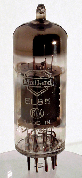
"The EL85 appears to be the little brother of the EL84 pentode"
The problem is, that family is rather big, so trying to find anything which looks remotely like it is a tough task, but that has got to be in the right ball park, and not off into the 6V6 family which it resembles a whole lot.
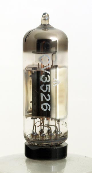
Mullard on the way back machine say "EL85 = 6BN5", which doesn't actually lead you anywhere, apart from to CV3526, looking like this little fella:-
More hunting came up with the E80L, which I never knew existed and as used for industrial measuring...or 6227.
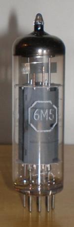
Then the EL80/6M5 which goes back to EL41..
We're looking for this after all:-
"With an anode load of 7500 Ohms this valve delivers its modest 2.5 Watts. This in the 1960s was the standard output for low cost audio products".
"As a single ended class A amplifier the E80L will deliver 2.7 Watts" so we are getting close.
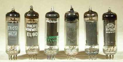
If we start going down the EL9x path it goes a different way:-
The EL91 was supposed to be a miniature 6V6.
"
EL91 is an audio output pentode valve for radio receiver use"
In single ended configuration it will produce 1.4 Watts, enough for a receiver.
If used in push pull an output of 4 Watts is possible, but this valve was not expected to be used for hi fi."
Anyone else who knows any more, welcome to find the mystery triode curves and all the other data, as there's not a lot apart from guessing or measuring.
I figured it's happy at 23-26m/a which means loading it up with a couple of 4k3-4k7 2W w/w resistors top and bottom at 320V HT, in fact almost identical to the Mosfet driver circuit the guy recommended in the last pages....
Nobody gives any inkling as to what the pentode is in the ECL83, no equivalents at all nothing!
(In fact the triode resembles nothing else either really)
There's a good reason for this.
This little ECL83 has got itself inside a lot of little headphone amps, and there has to be reason apart from being so small.
I shuffled through all the normal candidates.
EL83 (Forget it, ECL83 doesn't mean anything without the C!)
EL84, 6BQ5 etc
Then a little cryptic note came up
"The EL85 appears to be the little brother of the EL84 pentode"
The problem is, that family is rather big, so trying to find anything which looks remotely like it is a tough task, but that has got to be in the right ball park, and not off into the 6V6 family which it resembles a whole lot.
Mullard on the way back machine say "EL85 = 6BN5", which doesn't actually lead you anywhere, apart from to CV3526, looking like this little fella:-
More hunting came up with the E80L, which I never knew existed and as used for industrial measuring...or 6227.
Then the EL80/6M5 which goes back to EL41..
We're looking for this after all:-
"With an anode load of 7500 Ohms this valve delivers its modest 2.5 Watts. This in the 1960s was the standard output for low cost audio products".
"As a single ended class A amplifier the E80L will deliver 2.7 Watts" so we are getting close.
If we start going down the EL9x path it goes a different way:-
The EL91 was supposed to be a miniature 6V6.
"
EL91 is an audio output pentode valve for radio receiver use"
In single ended configuration it will produce 1.4 Watts, enough for a receiver.
If used in push pull an output of 4 Watts is possible, but this valve was not expected to be used for hi fi."
Anyone else who knows any more, welcome to find the mystery triode curves and all the other data, as there's not a lot apart from guessing or measuring.
I figured it's happy at 23-26m/a which means loading it up with a couple of 4k3-4k7 2W w/w resistors top and bottom at 320V HT, in fact almost identical to the Mosfet driver circuit the guy recommended in the last pages....
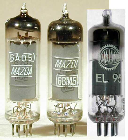
Here is the whole 6V6 family.
Officially it's tied up as an EL90 or something like that and the roots go back to 1936.
Funnily enough it's all in a page in German (a language I speak fluently)
Die 6V6 - Familie
So to use the rules of elimination here we go:-
This gets really confusing!
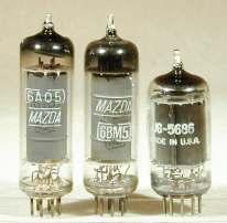
EL95 is basically a 6V6 in a 7 pin package, similar to 6005/6669/6AQ5..
EL90 is direct replacement for 6AQ5 which was claimed as the same as a 6V6.
(good luck!)
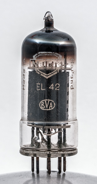
6AQ5 is also a down-rated 6V6, specifically designed for mobile service or a newer EL42...
6V6 is basically a down rated 6L6.
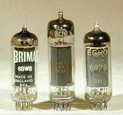
The 6BW6 is a 6V6 in a noval base.
More!
Or as made by the Russkies
So here we go on the 6BW6 V EL84 wars.....
http://www.diyaudio.com/forums/tubes-valves/223019-6v6-vs-el84-output-2.html
...which revolves around the 6V6 having more space between certain elements than the EL84/6BQ5/7189/7189A/6P14P resulting in lower gain...and of course being made 2 decades later.
Here we go again here are the EL83 and EL82!
We know the EL83/PL83 / EL82/PL82 are downgraded modified EL84 & all date from the same period 1951-2 (for TV), so what are the chances of the ECL83 being the same?
Well here's the line up:-
ECL80 1950.
ECL82 1956
ECL84 1958
ECL85 1961
ECL86 1961
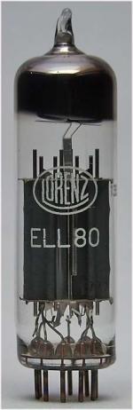
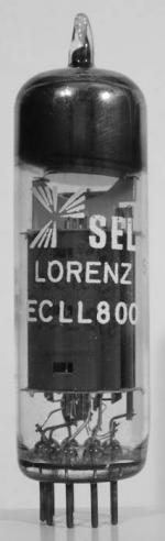
ELL80 = 2 x EL95 (ERK 6DL5!) So that's a 6V6 clone in there!
ECLL800 = same as ELL80 + a triode
Officially it's tied up as an EL90 or something like that and the roots go back to 1936.
Funnily enough it's all in a page in German (a language I speak fluently)
Die 6V6 - Familie
So to use the rules of elimination here we go:-
This gets really confusing!
EL95 is basically a 6V6 in a 7 pin package, similar to 6005/6669/6AQ5..
EL90 is direct replacement for 6AQ5 which was claimed as the same as a 6V6.
(good luck!)
6AQ5 is also a down-rated 6V6, specifically designed for mobile service or a newer EL42...
6V6 is basically a down rated 6L6.
The 6BW6 is a 6V6 in a noval base.
More!
Or as made by the Russkies
So here we go on the 6BW6 V EL84 wars.....
http://www.diyaudio.com/forums/tubes-valves/223019-6v6-vs-el84-output-2.html
...which revolves around the 6V6 having more space between certain elements than the EL84/6BQ5/7189/7189A/6P14P resulting in lower gain...and of course being made 2 decades later.
Here we go again here are the EL83 and EL82!
We know the EL83/PL83 / EL82/PL82 are downgraded modified EL84 & all date from the same period 1951-2 (for TV), so what are the chances of the ECL83 being the same?
Well here's the line up:-
ECL80 1950.
ECL82 1956
ECL84 1958
ECL85 1961
ECL86 1961
ELL80 = 2 x EL95 (ERK 6DL5!) So that's a 6V6 clone in there!
ECLL800 = same as ELL80 + a triode
Last edited:
So what was all that about?
To try to work out what exactly is inside the UCL83/ECL83.
The sheet pentodes in triode mode quotes the figures as the following:-
These look like a quite low gain triode,-
UCL83 Mu 9,4 gm 4.0ma/v RP 2,4K anode 250v Ia 45ma p=5.4W Family?
EL84 "family":-
E/PL83 25 13.5 1.8 300v 70 9W (high gain)
EL84 17 8.5 2 300v 65 12W (highish gain)
SV83 15 measured P Millett
EL86/PL84 7.5 7.5 1 200v 100 12W (low Z, low gain?)
11 P Millett measured 50 6.4W
6V6 "family"
EL90 10 5 2 315 40 14W (high Z low gain)
EL95/800 15 5 3 300 35 6W (higher gain)
6L6/KT66 8 4.7 1.7 300 125 15W (for example = low gain)
807 8 4.7 1.7 300 125 25W (low gain again)
EL82 8.8 9 1 250 75 9W
6V6 10 5 2 315 40 14W (idem to EL90!)
EL85, E80L & EL91 no figures available but suspect E80L are the closest match.
There is no match for the triode section which has Mu85 (half way between 12AT7 & 12AX7).
This higher gain triode is clearly to make up for the low gain of the pentode....
This ECL/UCL83 therefore has no equivalent.
Conclusion:-
It's has the low gain of the old style 6V6 family but the format of the EL83-84 family, bias voltages of -8>-11V so it can needs a high gain, high linearity first stag typical of a pentode or cascode amplifier.
Last edited:
To summarise:-
After all this long searching, the pentode section of the E/UCL83 seems to be closest match to the EL85/6BN5 (which as we saw is a junior cousin of the EL84).
However it is NOT based on the EL83/84 at all.
It is in fact an ancient budget design of lower output valve which goes right back to the dawn of mass radio.
This is why it would seem to have these larger spacing of internal grids and lower gain more in common with the equally ancient 6V6.
To get some history on this little sleeper, it came from the EL42.
Here is what it says and how that looked:-
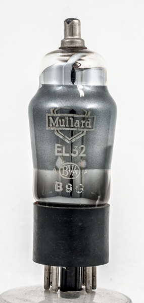
"The EL42 took over from the EL2 and EL32 and was in turn replaced by the EL95."
One thing in common, this replaced the old high current 4V, 7 pin base heaters with the lower powered 6.3V one at 0.2A, which with an extra triode ran 0.6A.
1954:-
Which was this just post war thing as the UK & Holland were recovering from wartime production needs, so these were the FIRST NOVAL OUPUT VALVES:-
1947
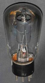
Based on this OCTAL thing looking like a 6V6 with top cap, & much less powerful:-1940
And finally the 1930s EL2 with side contacts and the rare top cap...
1934:- so predates the 6V6 and 6L6 family.....
These valves must have been the ones large numbers of people heard Lord Haw haw on.
Philips made a dual pentode version for push pull the ELL1, kind of several decades before their ELL800!
Bet those side contacts were fun for push pull!
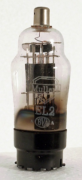
The EL1 is almost certainly a slightly modernised version of the late 20s, early 30s AC/PEN group of valves which looks like this, and has quite similar characteristics...
Those gold mettalic paints.....
And back to this:-
Hope you enjoyed the trip around Baker street.
There's nuthin new under the sun, least of all in a 60s Telly.
For the "budget" radio end in the UK, it was simply recycling and regurgitating the same old stuff for 50yrs, a bit like their motor industry.
So I am about to regurgitate it from Europe and pop it in a yankee amp with some tweeks to make it into "hi end" audio work!
What a laff!
After all this long searching, the pentode section of the E/UCL83 seems to be closest match to the EL85/6BN5 (which as we saw is a junior cousin of the EL84).
However it is NOT based on the EL83/84 at all.
It is in fact an ancient budget design of lower output valve which goes right back to the dawn of mass radio.
This is why it would seem to have these larger spacing of internal grids and lower gain more in common with the equally ancient 6V6.
To get some history on this little sleeper, it came from the EL42.
Here is what it says and how that looked:-
"The EL42 took over from the EL2 and EL32 and was in turn replaced by the EL95."
One thing in common, this replaced the old high current 4V, 7 pin base heaters with the lower powered 6.3V one at 0.2A, which with an extra triode ran 0.6A.
1954:-
Which was this just post war thing as the UK & Holland were recovering from wartime production needs, so these were the FIRST NOVAL OUPUT VALVES:-
1947
Based on this OCTAL thing looking like a 6V6 with top cap, & much less powerful:-1940
And finally the 1930s EL2 with side contacts and the rare top cap...
1934:- so predates the 6V6 and 6L6 family.....
These valves must have been the ones large numbers of people heard Lord Haw haw on.
Philips made a dual pentode version for push pull the ELL1, kind of several decades before their ELL800!
Bet those side contacts were fun for push pull!
The EL1 is almost certainly a slightly modernised version of the late 20s, early 30s AC/PEN group of valves which looks like this, and has quite similar characteristics...
Those gold mettalic paints.....
An externally hosted image should be here but it was not working when we last tested it.
And back to this:-
Hope you enjoyed the trip around Baker street.
There's nuthin new under the sun, least of all in a 60s Telly.
For the "budget" radio end in the UK, it was simply recycling and regurgitating the same old stuff for 50yrs, a bit like their motor industry.
So I am about to regurgitate it from Europe and pop it in a yankee amp with some tweeks to make it into "hi end" audio work!
What a laff!
Last edited:
Being as they were imported direct from the USA, that involved wiring the HT/Power transformers for the 2 amps in series.........How is that stable?.......ahum do you have idea what you are talking about?
The bias current through an output tube will drift with age, and the 8417 with it's high Gm has a reputation for drift, as well as cathode to grid shorts from oxide flaking. You can expect the idle current to drift with age, and possibly change drastically if an output tube fails. This will cause enough of an imbalance in two series wired amps to cause problems with overvoltage in one amp.
Back in the 60's, I often repurposed transformers from discarded junk for use as power transformers. I found that wiring two or three identical transformers in series across the mains to be a recipe for disaster....unless I wired the secondaries in parallel.
Note, three (and sometimes two) 400Hz military surplus power transformers can be used on 60 Hz in this manner.
I would suggest at least connecting the heater windings in parallel with some heavy gauge wire to force some degree of balance between the two transformers for when (not if) the load currents are not equal.
If your transformers were not designed for 230 volt operation, they probably weren't designed for 50 Hz either, and may get too hot. Removing some of the load may (one pair of tubes) may be a good compromise.
Hi.
Interesting coincidence I was just reading all about you about 5 mins ago, then you suddenly posted all this.
I wanted to ask a number of questions in fact about the driver, because I had come up with 4-5 really viable designs built around the elements I discussed above.
(The principal problem being the filament of the ECL83 will have to float BOTH halves ideally around 95-110v up), so you can see where that is inevitably leading.
As far as I am aware there is no difference in the 220V 50hz we have up here in the Baltic States and your 110V in the USA, except ours of course is about 1/3 of the price you pay, thanks to the oil shale deposits!
Being as those Bogen transformers get hot anyhow, it's not a bad plan to drop another 30-50W off them using just a pair of 8417 each
(and there's much lower distortion)
As for an amp drifting around a few m/a here or there at 650V.
10m/a inbalance at 650V is a fat lot more than 30-40m/a at the mains end.
In any case if it's going to blow up, it's going to blow up anyway, - the fuses are also in series, so one amp slides into an abyss, and the fuses are going to go, they both shut down instantly much faster than fast.
I think the 8417 has a totally undeserved reputation for unreliability.
High gain low impedance valves are/were the way to go.
TBH I've had quite a few AB2 amps years ago.
The scariest ones were always those crappy old EL34s with the screen grids melting (Mullard designed them to fail!), and of course the 807s lighting up if you had a bias supply fail or an anode resistor die.
All the GEC TT21 and other stuff was so well built, you could have a major "event" and still everything would be in one piece..(I had 2 old KT88 submarine PA amps like that, and you could get the anodes to glow red for hours with no worries at all!)
These seem very much the same, and they are being run with the same loads but hardly get warm. (Stereo).
They are part of a surround sound system anyhow.
There's a limit to how much dB you can cope with reproducing uncompressed 24bit music.
It rapidly approaches the SPL of the real concert venue, which of course not that many people know anything about anyhow (!)
I don't believe for one minute, they will keel over in that sort of way.
These Bogen amps were designed for flat out abuse for decades and thrashed constantly .
They also sound pretty good!
As far as I am aware there is no difference in the 220V 50hz we have up here in the Baltic States and your 110V in the USA, except ours of course is about 1/3 of the price you pay, thanks to the oil shale deposits!
When those amps were designed the electricity in the US was 115 / 230 volts at 60 Hz. it is now 120 / 240 volts 60 Hz. You have 50 Hz power which requires more iron in the transformers and more inductance in the primary to avoid core saturation.
Yes well if you look it up you will find the power is 230V in our country.
In the Amp spec I have unsurprisingly it states on the amp spec:-
Supply 117V 2,5A 50-60hz AC. (250W)
This means it is currently operating 1.7% BELOW the spec shown and according to the manufacturers spec.
Further:-
The 2, extra 8417 would consume 3.2A per pair MORE at 6.3V (20W), if I fitted all 4, and 120m/a static at 650V (78W), so a total of 100W more per PT which is probably 60% eff (so would be taking 40W more to produce in extra heat, so roughly doubling the heat dissipated).
As you can see I have substantially REDUCED the loading on each PT at zero signal by nearly 50% already as the mains voltage is 1.7% lower.
This means the units have considerably MORE reserves of current than they would otherwise have, and are consuming a little over HALF the power they would normally be asked to do.
This increased power supply stability means the voltage under full load is MORE stable not less, and of course one has to take care to run the right impedance back to the OPT from the speakers.
The use of 2 valves not 4, are leading to considerably lower THD distortion especially at lower frequencies, which as you can see have the most energy according to my calibration tests (where the speakers have the lowest impedance.)
So how many more people are going to tell me it's about to blow up, when it's working very conservatively within its correct design operating parameters?
---
NB:-I did finally locate the spec for the U/ECL83 type valve triode section and it's looking GOOD. Very good.
It resembles a good RF valve quite a bit, the 6ER5....no less and dates from the same year.
It's a much better triode than any 12AX7 clone will ever be.
Last edited:
Back to the fun and games of a new circuit iteration No1.
The primary idea being minimum parts count and remaining invisible with much lower distortion, hum etc.
What is better? To get a pentode to behave more like a triode, or triode(s) to behave more like a pentode?
Being as I determined the C_L83 variant has a triode something like a 6ER5, but now stuck with a pentode with a heater miles off earth, then we might as well use that heater potential for the triode too as CF.
The other clever bit is to buy a tiny input pentode off the shelf, as the local electronics shop has more than 50 in stock.
This one is going to end up mostly DC coupled too, and the data & curves look OK to me...
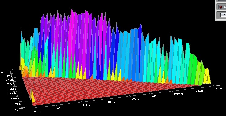
Here are the curves
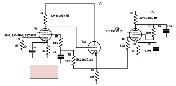
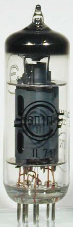
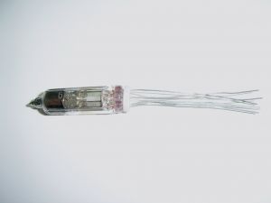
For those that don't know the 6Ж45Г-В is a submin wired ended version of the UHF wide band amplifier valve E280F, which again was one of the last things designed.
(6Ж9Г-В is a wired ended version of the E180F.)
They are all quite similar to the AC701/5840/EF732, on the basis, that if they're good enough to put inside a Lomo, Gefell, or Neumann microphone, they're good enough for my amplifer.
They all cost about 40cents here, or about 35p! NEW,
(although there's people trying to flog them on EBAY as "rare" for about 2-6USD).
They even crammed nuvistor versions of the thing into the MIG29!
The primary idea being minimum parts count and remaining invisible with much lower distortion, hum etc.
What is better? To get a pentode to behave more like a triode, or triode(s) to behave more like a pentode?
Being as I determined the C_L83 variant has a triode something like a 6ER5, but now stuck with a pentode with a heater miles off earth, then we might as well use that heater potential for the triode too as CF.
The other clever bit is to buy a tiny input pentode off the shelf, as the local electronics shop has more than 50 in stock.
This one is going to end up mostly DC coupled too, and the data & curves look OK to me...
Here are the curves
For those that don't know the 6Ж45Г-В is a submin wired ended version of the UHF wide band amplifier valve E280F, which again was one of the last things designed.
(6Ж9Г-В is a wired ended version of the E180F.)
They are all quite similar to the AC701/5840/EF732, on the basis, that if they're good enough to put inside a Lomo, Gefell, or Neumann microphone, they're good enough for my amplifer.
They all cost about 40cents here, or about 35p! NEW,
(although there's people trying to flog them on EBAY as "rare" for about 2-6USD).
They even crammed nuvistor versions of the thing into the MIG29!
Last edited:
- Status
- This old topic is closed. If you want to reopen this topic, contact a moderator using the "Report Post" button.
- Home
- Amplifiers
- Tubes / Valves
- Bogen beasts again