Now for the 2nd iteration of the driver circuit.
Actually it's pretty much the same thing apart from the impedances are different + the bottom input valve doesn't need to be a pentode.
In practice in behaves in a similar fashion at similar voltages/currents & not quite so much "Neve" stuck in there.
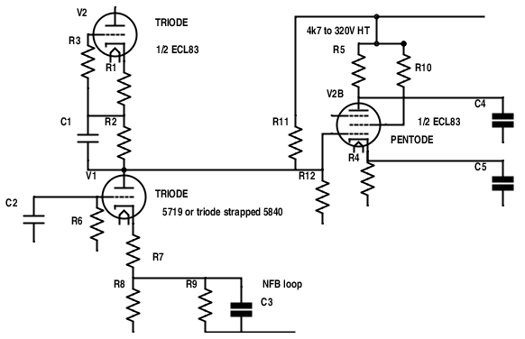
The heater differential will also be more like 30V between the 2 valve halves on this one, rather than about 10V on the last one, and that could be an excuse to use the UCL83 instead, although I'm not sure they series wired the heaters in them or parallel.
It DOES matter.
Actually it's pretty much the same thing apart from the impedances are different + the bottom input valve doesn't need to be a pentode.
In practice in behaves in a similar fashion at similar voltages/currents & not quite so much "Neve" stuck in there.
The heater differential will also be more like 30V between the 2 valve halves on this one, rather than about 10V on the last one, and that could be an excuse to use the UCL83 instead, although I'm not sure they series wired the heaters in them or parallel.
It DOES matter.
Last edited:
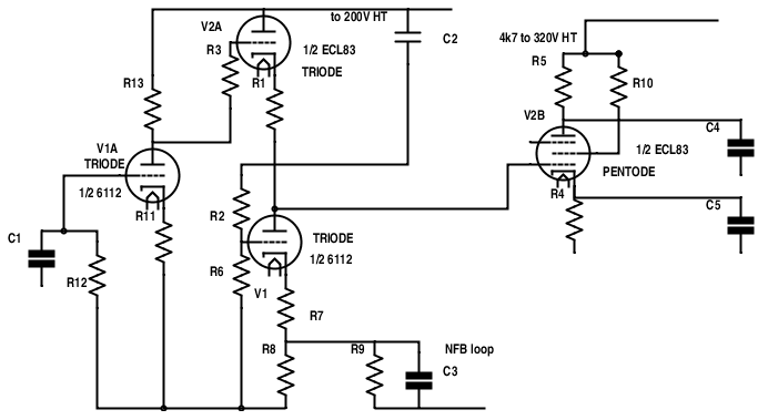
Another variation on a theme.
This one again, with different load impedances, less gain & more triode distortion.
This time the split heaters will see about 7V difference .
Of course it's now using one more valve with some PSR "a la broskie white"...
The majority of the gain will now be confined to the input valve which now has a Mu of 70, instead of the original 12AX7 (100) with all its attendant hum, noise, distortion et al.
This circuit is more similar to the original but with 2 more valves, DC coupling, and considerably better impedance & linearity.
To get a handle on all of it, this is a collection of most of the driver stages of the bogen amp, with the "much acclaimed" Dyna ST amp at the end.
There's 7027, 7591, 6L6, 6550, 8741 all those octal base things in there.
The Dynaco used EL34 (LAST), and made very few MkV1 with the 8417s in.
As you can see, there's almost no difference, so it's hardly suprising, that comprises what most people's education of how a valve amp should sound, and so do the Chinese who (fake) I mean, copy them...then call their factory a fancy "audio research" style name.
Quicksilver (8417)
Bogen M60 (8417)
Bogen MO30 6L6 (LTP)
Bogen MO100 LTP (6550)
MO100A (8417)
ST-70 (EL34)
Interesting? 🙄
Last edited:
Which of course is good reason to do something else. LTP of power pentodes( EL84 comes to mind ), with Schade local FB around just the output tubes themselves. Check out what happens to the pentode's plate curves under such FB topology...😀
http://www.diyaudio.com/forums/tubes-valves/271134-schade-cfb-exactly-equivalent.html
cheers,
Douglas
http://www.diyaudio.com/forums/tubes-valves/271134-schade-cfb-exactly-equivalent.html
cheers,
Douglas
Maybe I didn't make perfectly clear what the object of this exercise was.Which of course is good reason to do something else. LTP of power pentodes
If you notice is exactly what I am doing all in ONE valve, that's exactly the same size as the original 7247, but a quantum leap better, costing no more than 10-20 Euro for the whole conversion.
I reckon the little headphone amps using the ECL83 probably work quite well too,- even better if they were made to run SRPP into 300 ohms.
I mean,- you will never get a 12AU7 to conduct 25m/a with 4k7 loads.
The Rp of this triode (EL85?) strapped pentode is 2,4k instead of the original 60k...
The distortion falls by a factor of 4 using this idea, so judging by reports, something of the order of 0.05% THD is a strong likelihood.
The 12AU7 in the original 7247, is struggling to get to Rp of 7k.
Forget anything over 5m/a per section, as our mosfet friend reminded us, and THD is anything from 1.5-4%. No wonder it sounds bad.
I don't want the LTP.
We don't need it with such low impedances and such low output valve drive requirements, but we do need perfect balance.
Pretty much all the even order harmonics cancel out in the output stages, so the effort here is to drop odd harmonics to tiny figures.
This may be my final reason for opting for using an ultralinear or cascode input stage, rather than a plain triode.
What we are after is maximum linearity.
It's likely given the right front end, this will drop from 2% to well below 0.1% at 60W despite using minimal NFB.
If you notice, the requirement here, was to get a quantum leap in performance with an absolutely minimal parts count,- to the extent that I'm using sub-min valves so as not to have to put any more sockets in or waste more power or that very limited space.
I am absolutely convinced the output circuitry is fine.
All the indications from different sources show the OPT are well over-dimensioned and will never hit saturation, as well as being pretty much FLAT from below 8hz to 50khz at 100W rated with 2%THD.
That's good response by today's figures.
I don't believe the original THD figures, just as I don't believe those from China.
I reckon they must all be massaged at a frequency which suited them or plain made up.
Last edited:
There is nothing like taking a few days off the project to get some order in the brains and decision making processes.
Spending hours going through Russian sub-min valves, then realising they have a far larger more developed section than ever saw the light of day in the west, then comes the inevitable process of finding out who has it in stock, and at what price.
As a result of that, I decided to abandon any use of 6Ж45Г-В, as well as 6Ж39Г-В, and the 5840.
Some of the best pages were this:-
• View topic - Russian Tubes
Russian Tube Tester Files - Instrumental Curves and more
This left a choice of the 6Ж9Г / 6Ж9П which are essentially a E180F....as shown here
Amazingly the little wire ended submin is a version of the SAME THING!
That appears to be going the wrong way though, using lots of current in a high impedance high gain stage.
Another valve kept cropping up in Russia, which is a version of the well known EF86 running at 250V, called the 6ж32п.
There are 2 versions, the old Svetlana SPB /MSK version, and then this wire ended version.
(Btw:- During the war/siege Leningrad shared engineers with Melz Zelenogorsk)
If you keep looking you turn up with this amazing little beast made at NEVZ Novossibirsk (Siberia):-
6ж32б
Now the submin version has at least one thing going for it:-
The microphonics, the bane of EF86, 6BR7/6BS7, are practically non existent.
They quote them as 5x LOWER than the EF86.
Inter-electrodes capacitances are sensibly the same.

But here is even more:-
It can only run at 120V officially , but that can be taken with a pinch of salt.
It costs 45 rouble (which just now is about 65p in British money).
They are well known in Russia:-
Now take a look at this:-
Tube Tester Files - 6J33P (EF86)
DISTORTION AT 10V OUTPUT 0.05%.
Being as the following driver stages are not going to add to that significantly because they have lower than unity gain, & the output transofrmers are top rate, it's really starting to look something special for 2/3 maximum amp output.
0.1% THD from 2 amps total 120W+ , with DC coupling mostly everywhere, I like the sound of that...
😀
Spending hours going through Russian sub-min valves, then realising they have a far larger more developed section than ever saw the light of day in the west, then comes the inevitable process of finding out who has it in stock, and at what price.
As a result of that, I decided to abandon any use of 6Ж45Г-В, as well as 6Ж39Г-В, and the 5840.
Some of the best pages were this:-
• View topic - Russian Tubes
Russian Tube Tester Files - Instrumental Curves and more
This left a choice of the 6Ж9Г / 6Ж9П which are essentially a E180F....as shown here
Amazingly the little wire ended submin is a version of the SAME THING!
That appears to be going the wrong way though, using lots of current in a high impedance high gain stage.
An externally hosted image should be here but it was not working when we last tested it.
Another valve kept cropping up in Russia, which is a version of the well known EF86 running at 250V, called the 6ж32п.
There are 2 versions, the old Svetlana SPB /MSK version, and then this wire ended version.
(Btw:- During the war/siege Leningrad shared engineers with Melz Zelenogorsk)
If you keep looking you turn up with this amazing little beast made at NEVZ Novossibirsk (Siberia):-
6ж32б
An externally hosted image should be here but it was not working when we last tested it.
Now the submin version has at least one thing going for it:-
The microphonics, the bane of EF86, 6BR7/6BS7, are practically non existent.
They quote them as 5x LOWER than the EF86.
Inter-electrodes capacitances are sensibly the same.
But here is even more:-
It can only run at 120V officially , but that can be taken with a pinch of salt.
It costs 45 rouble (which just now is about 65p in British money).
They are well known in Russia:-
Now take a look at this:-
Tube Tester Files - 6J33P (EF86)
DISTORTION AT 10V OUTPUT 0.05%.
Being as the following driver stages are not going to add to that significantly because they have lower than unity gain, & the output transofrmers are top rate, it's really starting to look something special for 2/3 maximum amp output.
0.1% THD from 2 amps total 120W+ , with DC coupling mostly everywhere, I like the sound of that...
😀
Last edited:
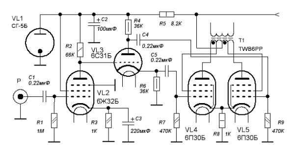
The last bit I wanted to add to this bogen amp is a decent bit of voltage stabilisation, which was sadly lacking originally and drops the 50hz ripple through the floor.
Fortunately the Russians also developed a sub miniature tube shown on the last circuit which is brilliant.
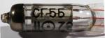
There are 1000s surplus and usually cost about 50cents...the SG5b-V
These devices are pretty much the same as zeners, and not much bigger.
Put 2, in series you can regulate the OP valve screen valves fine (2 x 150 = 300V), so perfect for eg. an 807 screen.
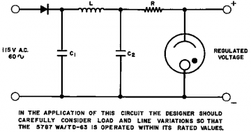
The US equiv is the Sylvania 6308 series at 87v, 5644 for 90V, 5787 which gives 100V, 6213 for 130V but no Sylvania wire ended one for 150v....
The SG5b fills this gap perfectly and the 6p30B delivers a lot more current than the 5902.
Put another small zener in series and you can adjust the thing which ever way you want so long as the steady current draw is between 5-10m/a, otherwise you will need to add a stabiliser valve circuit.
Funnily enough the 6P30b above works beautifully as a series regulator valve also...
Here's the 5902 circuit it can be substituted in:-
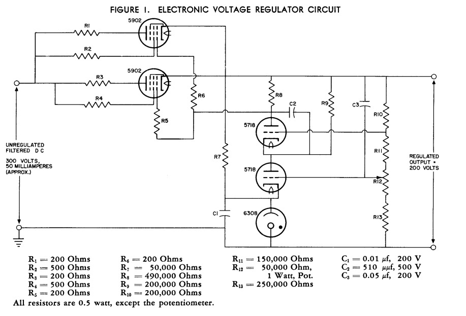
What's not to like?
😀
Fortunately the Russians also developed a sub miniature tube shown on the last circuit which is brilliant.
There are 1000s surplus and usually cost about 50cents...the SG5b-V
These devices are pretty much the same as zeners, and not much bigger.
Put 2, in series you can regulate the OP valve screen valves fine (2 x 150 = 300V), so perfect for eg. an 807 screen.
The US equiv is the Sylvania 6308 series at 87v, 5644 for 90V, 5787 which gives 100V, 6213 for 130V but no Sylvania wire ended one for 150v....
The SG5b fills this gap perfectly and the 6p30B delivers a lot more current than the 5902.
Put another small zener in series and you can adjust the thing which ever way you want so long as the steady current draw is between 5-10m/a, otherwise you will need to add a stabiliser valve circuit.
Funnily enough the 6P30b above works beautifully as a series regulator valve also...
Here's the 5902 circuit it can be substituted in:-
What's not to like?
😀
Last edited:
It looks like this could be the last post on here for various reasons:-
I searched to find ANY previous amplifier which ever used a pentode as phase inverter and finally came up with one dating back to August 1939 hosted on Oestex.
This a very good design, with some rather novel ideas.
The original image was way too big, so I reduced it to a readily visible form.
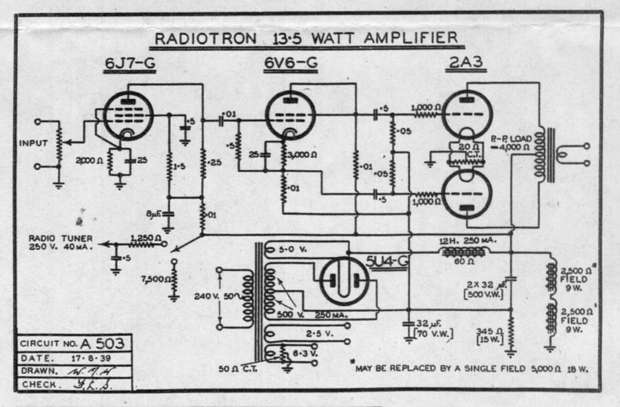
The 6V6 is connected as a power triode, so behave in an extremely similar way to the EL41/85/_L83 based tube proposed, but there, all AC coupled.
The 6J7 is almost exactly a 6J5 triode with an extra grid, so it shows the plan to drive the Bogen 100A amp with an ECL83 in the place of the weak old 12DW7 is very good, and will turn out extremely well.
I made some extra refinements to the circuit by adding a Russian СГ5ь 150V series stabiliser into the sensitive input valve circuit.
That effectively removes all the ripple from there.
This was the source of a lot of the noise and hum as it stands and would even better support full DC coupling.
Because of the "deafening" cries of interest shown in modification of any of the Bogen style amps shown above,(applicable to ST70s also) and despite over 1000 views, that will now be it folks!
😱
I searched to find ANY previous amplifier which ever used a pentode as phase inverter and finally came up with one dating back to August 1939 hosted on Oestex.
This a very good design, with some rather novel ideas.
The original image was way too big, so I reduced it to a readily visible form.
The 6V6 is connected as a power triode, so behave in an extremely similar way to the EL41/85/_L83 based tube proposed, but there, all AC coupled.
The 6J7 is almost exactly a 6J5 triode with an extra grid, so it shows the plan to drive the Bogen 100A amp with an ECL83 in the place of the weak old 12DW7 is very good, and will turn out extremely well.
I made some extra refinements to the circuit by adding a Russian СГ5ь 150V series stabiliser into the sensitive input valve circuit.
That effectively removes all the ripple from there.
This was the source of a lot of the noise and hum as it stands and would even better support full DC coupling.
Because of the "deafening" cries of interest shown in modification of any of the Bogen style amps shown above,(applicable to ST70s also) and despite over 1000 views, that will now be it folks!
😱
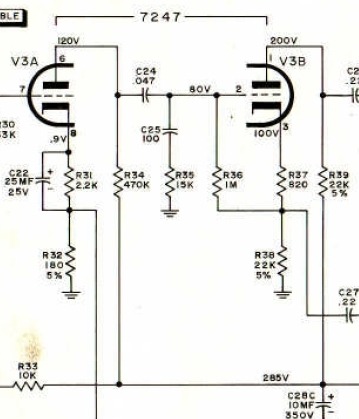
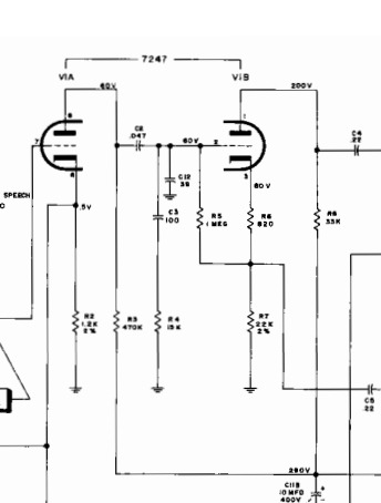
It may be of interest to see how all this worked out.
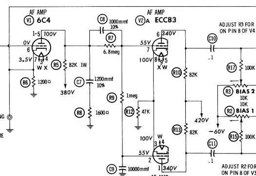
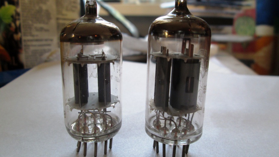
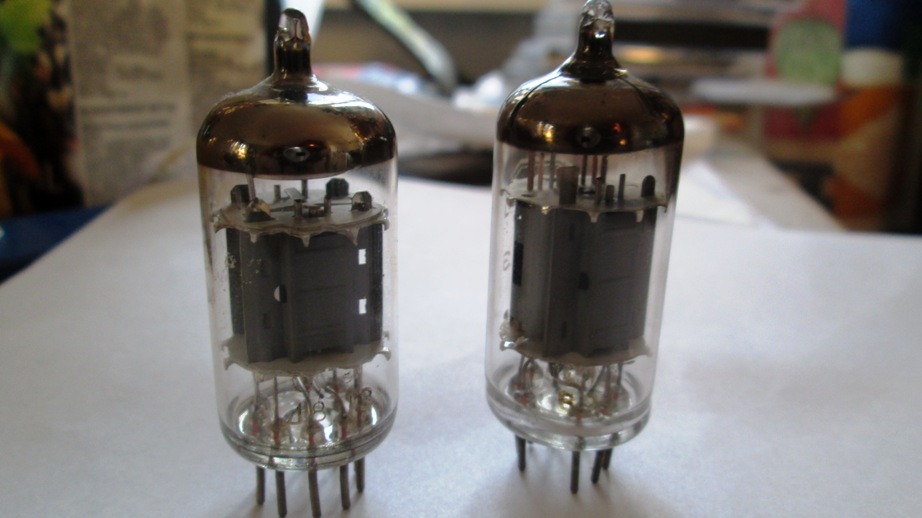
The 7247 original design was removed and the ECL83 was installed in its place.
Just for fun, the LH amplifier remained original (just with my little tweak to treble the current of the inlet hi mu valve, which worked so well), so it was the RH amp that got the new drive.
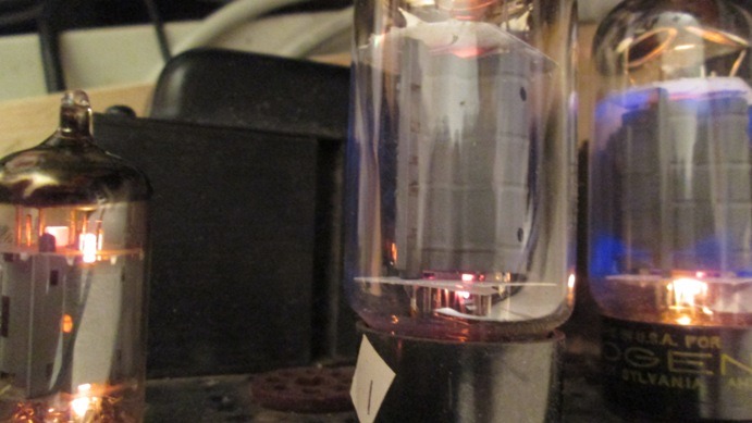
Here it is folks.....OLD versus new:-
The 7247 driver/ps...
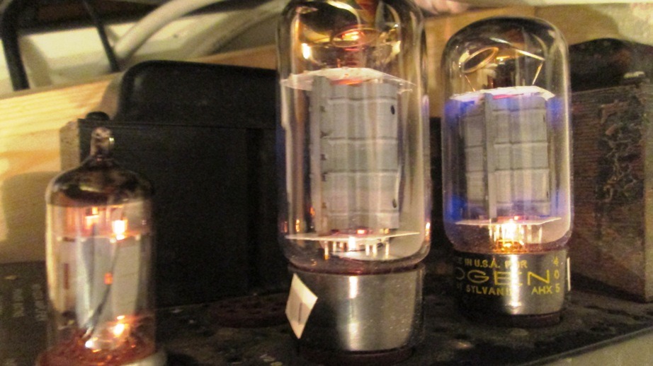
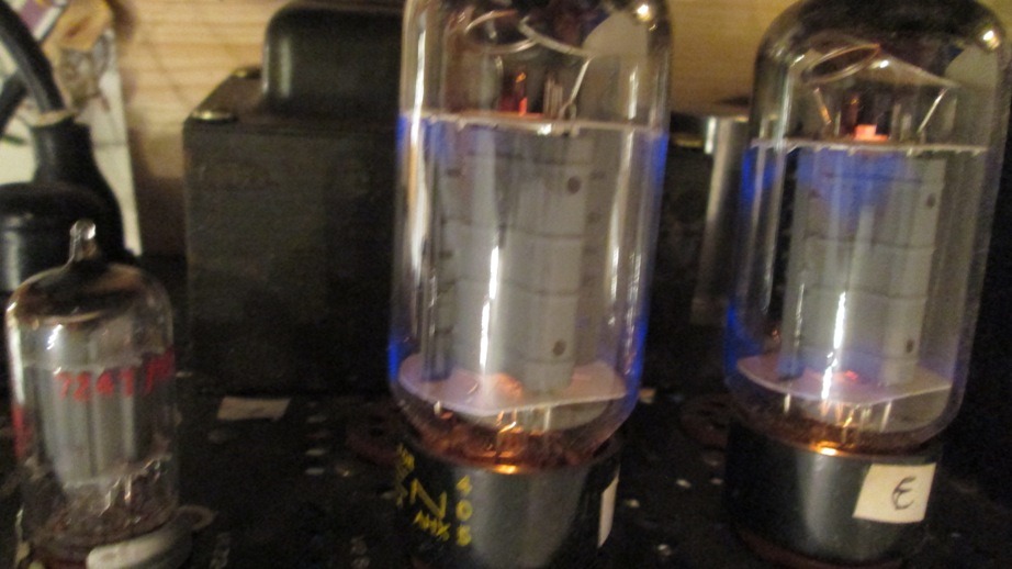
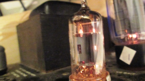
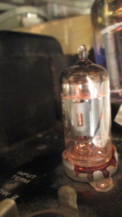
The new driver/ps, they sure glow a fair deal brighter....
In natural unplugged light they don't look so much different...
So here it is...
Compared with the (tweaked) old one
The 7247 original design was removed and the ECL83 was installed in its place.
Just for fun, the LH amplifier remained original (just with my little tweak to treble the current of the inlet hi mu valve, which worked so well), so it was the RH amp that got the new drive.
Here it is folks.....OLD versus new:-
The 7247 driver/ps...
The new driver/ps, they sure glow a fair deal brighter....
In natural unplugged light they don't look so much different...
So here it is...
Compared with the (tweaked) old one
Last edited:
So how did it sound??
TBQH when I started it all up at about 2am the new version sounded simply DREADFUL, Masses of cross over distortion, and clear intermodulation distortion.
Usual heart searching follows....what on earth had been done wrong?
Then we start measuring voltages.
The bias voltages of a power pentode even triode connected are simply light years different compared with a 12AU7, so after some quick checking it turns out the Pentode section of the ECL83 was turned hard on, and lots of hum was bleeding in too.
The cathode resistor was obviously way too low, and an attempt to get it to run 15-25m/a current clearly was NO GO.
It needed about -10V at the grid, not -5V.
Adding to this and the triode section of the ECL83 was also vastly different from the 12AX7, and this also needed far more bias.
The long and the short came to changing loads of values and junking the idea of a step down dropping resistor/on the original circuit.
Much to my suprise the "L" part of the ECL83 totally cleaned up, by using a lot less current.
I moved ALL the anodes up to the same common supply as the G2 of the output valves, junked the bleed resistor and just put 100R instead in there with the decoupling capacitor. (so theoretically running about 320V).
Now running an anode load of only 62K on the "c" part of the ECL83 comes as a bit of a suprise, and moving the load resistors of the "L" section from 4k7 to 6k2 (A & K), with 820 ohm cathode/G1 bias with only 11.5m/a also was a bit of a shock, but BOY does it work!
Previously where the amplifier would be clipping at about 40-50W, it was CLEAR and CLEAN as a bell at easily over 80W. (it's doing clean 35V into 15ohm at 30HZ..)
Job done!
All that remains to do is to swop out all the bits of the LH amp doing the same to that one.
There was more to it than that.
The essential was a shining success, and proof the initial hunch about the amps being poor because of the preamp and driver were dead on the money. 😀

That's now what I call a serious Kick - A...s amplifier, driving the output valve load impedance (22k) with a driver anode impedance of only 2K and load impedance of 7k from a 320V supply.
This gives serious nice linear class AB2 drive, instead of:-
..some whimpy little triode struggling to overcome the impedance mismatches on the phase splitter, & the input noise coming from running a 12AX7 at only 60-80v at only 400uA, as in the original circuit.
TBQH when I started it all up at about 2am the new version sounded simply DREADFUL, Masses of cross over distortion, and clear intermodulation distortion.
Usual heart searching follows....what on earth had been done wrong?
Then we start measuring voltages.
The bias voltages of a power pentode even triode connected are simply light years different compared with a 12AU7, so after some quick checking it turns out the Pentode section of the ECL83 was turned hard on, and lots of hum was bleeding in too.
The cathode resistor was obviously way too low, and an attempt to get it to run 15-25m/a current clearly was NO GO.
It needed about -10V at the grid, not -5V.
Adding to this and the triode section of the ECL83 was also vastly different from the 12AX7, and this also needed far more bias.
The long and the short came to changing loads of values and junking the idea of a step down dropping resistor/on the original circuit.
Much to my suprise the "L" part of the ECL83 totally cleaned up, by using a lot less current.
I moved ALL the anodes up to the same common supply as the G2 of the output valves, junked the bleed resistor and just put 100R instead in there with the decoupling capacitor. (so theoretically running about 320V).
Now running an anode load of only 62K on the "c" part of the ECL83 comes as a bit of a suprise, and moving the load resistors of the "L" section from 4k7 to 6k2 (A & K), with 820 ohm cathode/G1 bias with only 11.5m/a also was a bit of a shock, but BOY does it work!
Previously where the amplifier would be clipping at about 40-50W, it was CLEAR and CLEAN as a bell at easily over 80W. (it's doing clean 35V into 15ohm at 30HZ..)
Job done!
All that remains to do is to swop out all the bits of the LH amp doing the same to that one.
There was more to it than that.
The essential was a shining success, and proof the initial hunch about the amps being poor because of the preamp and driver were dead on the money. 😀
That's now what I call a serious Kick - A...s amplifier, driving the output valve load impedance (22k) with a driver anode impedance of only 2K and load impedance of 7k from a 320V supply.
This gives serious nice linear class AB2 drive, instead of:-
..some whimpy little triode struggling to overcome the impedance mismatches on the phase splitter, & the input noise coming from running a 12AX7 at only 60-80v at only 400uA, as in the original circuit.
Last edited:
Here are some final figures & some thoughts :-
Factory E*L83 pentode section:- anode impedance at 170V (as pentode 56K, 65k at 200V)
Original Bogen circuit 7247 section 2 anode load 33k, voltage across valve 107V anode impedance, 6k5....
Voltage across it now (Anode 220V, cathode 85V = 135V)
Recommended anode load 6.5-7.5K
Actual load 7k1.
Anode impedance Triode connected 200V 2,4K,
This at 135V is probably 1,8K, - a very low figure for any driver valve.
For ref:- 1/4 of the original circuit, the Va is 25% higher and the Ra load impedance is nearly 5x lower, so this circuit meets 8417 requirements for class AB2.
Va 135V
g1 bias -10V.
Rg1-k 470k.
Ig2 1.6 m/a
Ia 10 m/a (Original 7247-[12AU7] Ia 3.2m/a, voltage across valve 107V, Mu20)
Mu 9.4
Power dissipation in "L" section 1.6W (quite hot to touch, original 0.34W)
This means the external screening has to be removed, or it will get too hot, but it turns out this valve doesn't need anyway. On the original circuit the 7247 without an external screen was much noisier with a lot of PS hum & noise at full volume.
NEW Insertion loss 0.9 AC (input 25VRMS, output 22.5V RMS)
Original phase splitter AC drive insertion loss 0.6 (input 25V output 15V....), which is why it was being driven into distortion in both the preamp stage and phase splitter stage leading to heavy inbalance at high signal levels.
EC*83 Triode section input stage.
Va 210V (original Bogen design 60V was increased to 135V)
Ia 1.4m/a (original Bogen design 425uA)
Anode dissipation 300mW (originally 20mW changed to 120mW)
Anode impedance 33k (original 7247 80k)
Mu 85 (original 7247,section 1 = 100)
Gain 50 (input 500mv output 25V)
Vk 1.82V (originally 0.5V)
Rk 1k2
Coupling capacitor 0.047uf (unchanged -3dB at 7hz)
Output circuit.
Original output coupling capacitor 0.22Uf into 22k gives -3dB at 33hz.
NEW coupling capacitor 0.47Uf " -3dB at 15hz
Va 8417 660V.
Bias -17.5V
Transconductance 23ma/V. (eg. 6L6, 6ma/V)
Drive requirements of 2 x 8417 valve in AB1 class original amplifier 29V (110W)
Drive requirements of 8417 in AB2 class (Grid current >1.5m/a) 39V (135W)
Voltage drop over G1 resistor 1V.
Maximum grid drive to 8417, +4V positive.
Output transformer data, -0.5dB at 20hz. 😎
Last edited:
Looks like 2 x 6HB5 or 21JV6/21HB5 TV Sweep tubes in parallel would give an equivalent (same gm and Watts) to the 8417, except g2 screen voltage would need to be 150 V instead of 300V. (21JV6 $3 each)
Have to agree on the absurdity of converting the Bogens to KT88 etc.
The 8417 datasheet plate curves look awful, I assume there are some errors in the graphing (300V g2).
21HB5 etc. look MUCH better. Although, clearly more 2nd harmonic.
http://frank.pocnet.net/sheets/123/6/6HB5.pdf
http://frank.pocnet.net/sheets/168/8/8417.pdf
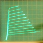
Screen grid drive for the 6HB5 though is fabulous:
Have to agree on the absurdity of converting the Bogens to KT88 etc.
The 8417 datasheet plate curves look awful, I assume there are some errors in the graphing (300V g2).
21HB5 etc. look MUCH better. Although, clearly more 2nd harmonic.
http://frank.pocnet.net/sheets/123/6/6HB5.pdf
http://frank.pocnet.net/sheets/168/8/8417.pdf
Screen grid drive for the 6HB5 though is fabulous:
Attachments
Last edited:
There's quite a bit of debate about the 8417.
Apparently it was quite a tricky thing to put together.
That would make sense, being some of the very last designed and made.
A valve with an anode rating of over nearly 700V on an octal base, but a gain as high as that, has got to have far more precise assembly quality control than the run of the mills stuff with wider spacing and lower gain dating mostly from the mid 30s.
My first step immediately on changing the drive impedances and opting for only single pairs of output valves was to put 5.5R resistors in the cathode circuit, so as I could actually check what the cathode current was and tiny presets on the bias supply so I could get the idle current the same.
Next suprise of course was to find out there was one "weaker" valve from the 4, so that needs to be replaced (although I've been able to tweak it a bit).
As this would have gone largely undetected in the original amp, I leave to imagine the kind of non linearities the original arrangement made.
Running just a pair actually has many advantages, not least of which is 3.2A less heater current draw, (that's 20W less folks!) and a much more stable g2 supply, because it's not being dragged down by an extra 40 ma of grid current.
In fact, on full load tests with my torture CD, I only saw a drop of about 20V on the anode supply, and about the same on the g2/preamp circuit supply.
(Although it's getting some extra regulation put in soon it's not high priority).
That was all enough at 30hz to get smoke pouring out of one speaker (doesn't it smell great!) and compared with the average old 5U4/valve rect style circuit, it's peanuts.
Tbh, I've never seen or heard an amplifier recently that generates such large speaker voltages at frequencies between 20-40hz.
I wouldn't mind betting it would fry a pair of those mega expensive Tannoy things I was asked to test recently. 😀
Next project is something completely different.
This time, much older Bogen units (1955) consists of taking 2 monobloc DB110 completely to pieces (one of the best 6V6 amps ever made), throwing out the 110V mains transformers, dropping the whole lot into a new chinese chassis with 230V power, and rebuilding the driver circuits in a similar way to this one to make a proper stereo pair on ONE chassis.
Last edited:
Just a little more info on the MO-200A
The Mighty Bogen MO-200A - AudioKarma.org Home Audio Stereo Discussion Forums
The Mighty Bogen MO-200A - AudioKarma.org Home Audio Stereo Discussion Forums
Hmmm, so the Bogen OTs have a 4750 Ohm primary. Looks like most any typical bigger audio tube will drive them after all, just needs a beefier driver circuit.
I'm not so impressed with the Bogens now. Too many Hi Z windings on them for good bandwidth. Wimpy driver circuits. Economy class PA amps, period.
Just some TV Sweep tubes into a low primary Z, 100 Watt Edcor, with local + global FDBK, would blow the Bogen away.
The used amplifiers on Ebay are a silly waste of money. That includes the Cit II, Macs and all the other over hyped amps. (while I'm dishing dirt, I might as well get them all!) The magic technique is just local + global feedback for low Zout into a low Z primary OT and a solid power supply. Anyone can do that, and cheaply with TV Sweep tubes, which can push the current. Classical audio amps just never made it into the modern era of high current tubes. (with a few notable exceptions)
Last edited:
Any more nonsense you want to talk, or is it jealousy counts for more? 🙄Hmmm, so the Bogen OTs have a 4750 Ohm primary.
Looks like most any typical bigger audio tube will drive them after all.
(AND SOUND TERRIBLE)
I'm not so impressed with the Bogens now. Too many Hi Z windings on them for good bandwidth.
(SO HOW COME THEY ARE FLAT+/1 0.5dB FROM 20z-50khz?)
Wimpy driver circuits. Economy class PA amps, period.
(NO, HIGH GAIN OUTPUT VALVES DIDN'T NEED BIG DRIVE)
I thought you would understand that.
Also most sweep tubes can only run g2 of about 150-200V which isn't a lot of good.
Just some TV Sweep tubes into a low primary Z, 100 Watt Edcor, with local + global FDBK, would blow the Bogen away.
(YES LIKE YOUR EDCOR ARE CRAP COMPARED WITH THE TRANSFORMERS BOGEN WOUND THEMSELVES!)
The used amplifiers on Ebay are a silly waste of money.
YES LIKE 2 EXCELLENT QUALITY 100W AMPS CAPABLE OF BEING UPGRADED I PAID A TOTAL OF 350USD FOR is a "silly waste of money!"
Last edited:
According to the above linked thread on AudioKarma, the Bogen bandwidth was found to be flat only to 10 KHz, and the feedback winding was found to be poorly coupled to the low Z output taps.
The Edcors are flat to 20 KHz in typical circuits, and with low Z drive and a low Z primary can achieve 30 KHz.
The 8417 tubes do not have aligned grids, this accounts for the high screen currents drawn, and strange plate curves. I would say these tubes were specially developed for Bogen so that a cheap amplifier could be made with a wimpy driver. The poor power supply regulation for the screen and bias voltages in the Bogen amp cause the distortion to go out of control at high power. 6%
The low bias currents in the Bogen amp caused crossover distortion, and the bias adjustment range won't allow fixing that. There is no AC balance control. There are no individual bias adjustments, so matched tubes (quads no less) have to be used.
Then the Bogen design had an outright biasing error issue in the 7247 stages that caused it to "pulse" at high power levels. Apparently never corrected, since the same problem occurs in other Bogen models.
It may have been a bargain, but you have NO choice but to re-design the Bogen amp. Using Edcor OTs and sweep tubes can get one in the same price range if some ingenuity is used for the power supply xfmr (industrial conversion xfmr or Ebay stuff) With $5 sweep tubes, one can afford to fill the closet with spares.
Last edited:
Actually if you read the whole long thread,there were reasons for the poor bandwidth that were a plus for PA use,The thread goes on to give schematics and distortions of both the 8417, and 6550 conversions to a good audio amplifier that would rival many.The output transformer is actually pretty good when used with the proper taps.
Post 483 sums it up
http://www.audiokarma.org/forums/showthread.php?t=556575&highlight=mo200&page=33
Post 483 sums it up
http://www.audiokarma.org/forums/showthread.php?t=556575&highlight=mo200&page=33
Last edited:
Work-arounds can sometimes produce miracles, as long as one knows what all the deficiencies are. Hats off to Dave G. for a tour-de-force of revealing the limitations, with superb work-arounds for fixing them, on that amplifier.
My comments about Edcor OTs were not meant to endorse them as anything special, just economical, reasonable performers. The limitations of the Edcor OTs have the unexpected effect of nearly forcing one to use the very best topologies to work around them, and then the results can be quite good.
Local feedbacks from the primary side of the OT (Cit. II, ....), CFB/Unity coupled (Mac, Crowhurst Twin, Circlotron, AR ....) point the way. My issues with the classics are mostly over hyped pricing, its not that hard to do local Fdbk. (Pete's DCPP, RCA 50 Watter,... etc)
I would be quite happy if Edcor would use split bobbins with balanced windings and more interleaves, providing the price doesn't go though the roof.
The TV Sweep tubes often get dismissed as kinky horrors. The reality is that some have completely unobservable kinks (always check on a curve tracer, grid alignment is a factor, the good ones are Top Secret), and any kinks are in the low plate voltage region anyway (due to low screen V), well out of the way of the load line. Their high current capability is a God-send though for using low primary Z cheap OTs.
Last edited:
I didn't have a good opinion of the MO-100 and 200 until Dave G. took on that project,I was surprised it could be made into a decent amp.
- Home
- Amplifiers
- Tubes / Valves
- Bogen beasts again