I don't understand.
Are you saying that a direct connection to the chassis (not using the resistor and cap 'isolation' idea) is better, that the C302 filter cap should be connected to the chassis directly....
or:
that instead of connecting the chassis ground via the resistor/cap at the heater ground, it's better to connect it (still using the resistor/cap) at C302?
I mean do not use resistors and caps. Connect the cap directly, it will be the best reference point for all currents consumed by the amp, to eliminate dirty currents through ground loops.
I agree that the heater CT is not the obvious place to connect to the chassis.
The secondary transformer CT is the worst possible point to ground, and it is most common mistake that leads to hum. Even worse with SS diodes, that caused the myth that vacuum rectifiers sound better. But it does not matter where you ground the heater CT, there is no current supply through it.
In my home builds, sometimes I've used a test wire (alligator clips) to compare different ground points to get the one with the least noise.
No need to, if you imagine that all wires have resistance, and think about currents that flow through them causing voltage drops. Currents charging caps are the worse evil, they have to be separated!
Correct; sorry for the incorrect 'quote'.No, I did not say that. I said, that bolts have to be insulated from the transformer bell. That's it. One bolt can be connected to the bell to ground it, it would not cause a shorted loop. If you add nuts between the chassis and the transformer for air flow, the grounding lug will be tightly squeezed between 2 nuts, that is fine for me, however not for UL.
Do not do that. Instead, ground the negative end of C302 filter capacitor.
Grounding to the chassis is always a great topic for disagreements!
")
http://www.valvewizard.co.uk/Grounding.pdf
I don't understand.
Are you saying that a direct connection to the chassis (not using the resistor and cap 'isolation' idea) is better, that the C302 filter cap should be connected to the chassis directly....
or:
that instead of connecting the chassis ground via the resistor/cap at the heater ground, it's better to connect it (still using the resistor/cap) at C302?
I agree that the heater CT is not the obvious place to connect to the chassis.
I'd think that in a 'kit' this would have been worked out?
One problem may be which holes in the ground circuit of the PCB are available.
In my home builds, sometimes I've used a test wire (alligator clips) to compare different ground points to get the one with the least noise.
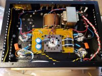
In this A9 kit I have, the negative end of the C302 filter cap (big black one on the PCB in photos) is tapped into the common circuit ground on the PCB. I have no idea where the ground for transformer is located as per the schematics that came with the kit. Does anyone out there with direct experience with this kit have any experience with this they can share because I am really confused on this grounding, earthing issue? Here is what she looks like now:


Hi Anatoliy,
Just curious, where do you connect the HT centre tap? I know this is where very distorted peak currents flow. I connect it further downstream.
It does not matter, it does not draw current through the center tap. It is too tiny to cause any significant voltage drops on ground wires.
Grounding to the chassis is always a great topic for disagreements!
http://www.valvewizard.co.uk/Grounding.pdf
...because there is infinite number of ways do do it wrong, but only one to do it right!
I have no idea where the ground for transformer is located as per the schematics that came with the kit.
The charging the cap loop through rectifiers must be closed through the first filter cap. Then the negative wire goes to the negative lead of the second cap, and positive goes to the positive lead through the choke.
Or did you ask about the shield between windings inside the transformer? To the same lug that grounds the chassis.
...because there is infinite number of ways do do it wrong, but only one to do it right!
..never lacking in self-confidence!
It's always amusing for me, as a beginner who knows little, to sit back and watch experts slugging it out.
Wavebourn: Ground circuit to chassis at power supply filter capacitor
ValveWizard: Ground circuit to chassis as far from filter caps as possible, at the signal input jack
Perhaps that explains why I sometimes resort to alligator test lead and listening/measuring hum levels!
Tim:I have no idea where the ground for transformer is located as per the schematics that came with the kit.
I don't think your power transformer has a 'shield' lead from the transformer?
My fault for showing the A10 schematic a while back.
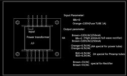
Does the diagram below (from LongRoad) show the connections (leads) from your transformer?
Assuming your PT has no shield lead:
The PT body is grounded to the chassis via the bolt where you have connected the 'green' AC safety wire.
From your photos, it looks like the black HV center tap lead is soldered to the PCB ground plane, close to the transformer, and also close to the negative connection for the filter caps.
So the question is how and where do you connect a wire between the circuit ground and the chassis. The chassis end should be a lug securely bolted with a spur washer to bare chassis metal. Get instructions from Wavebourn on where to connect the other end of that wire!
Attachments
Wavebourn: Ground circuit to chassis at power supply filter capacitor
I meant, at the point where all high current loops are being closed. It is the "cleanest" point in the amp, so if other components connected to the amp cause ground loops, there will be no harm, since no dirty currents flow through ground loops.
Did you get it now? No black magic here, just application of the same Ohm's law, and logical thinking.
The charging the cap loop through rectifiers must be closed through the first filter cap. Then the negative wire goes to the negative lead of the second cap, and positive goes to the positive lead through the choke.
Or did you ask about the shield between windings inside the transformer? To the same lug that grounds the chassis.
All of the above probably - sorry but first statement went whistling over my head. Complete noob here building my first kit with the absolute worst documentation I have ever seen anywhere. Anyway trudging along here just trying to make heads or tales of this and just wanting to make sure I don't melt this thing down when I energize this puppy for the first time (soon). I think I have it assembled correctly between the differing schematics I have seen using 120V household power from plans that say 220V - anyway I think I have the transformer stuff all sorted plus wiring but still trying to figure out where the heck to put the chassis grounding bolts as it shows 2 locations on the schematics I have posted previously (couple of posts before this one). Anyway got the green wire from the IEC connector onto the power transformer bolt inside the case. Can't see any transformer grounding thingy anywhere and I think I am more or less ready to power this sucker up and see what happens after just completing a whole wack of continuity checks...
My guess is it is going to hum like a banshee but will see....
Will I kill the thing if I apply power (using a variac plugged into a dim bulb tester and slowly dialing up the voltage) to the unit before I install the tubes? Thinking I can measure all the secondary winding outputs to see what voltages I am getting...
Here is my Dim Bulb tester (proof it is working correctly): YouTube
I meant, at the point where all high current loops are being closed. It is the "cleanest" point in the amp, so if other components connected to the amp cause ground loops, there will be no harm, since no dirty currents flow through ground loops.
Did you get it now? No black magic here, just application of the same Ohm's law, and logical thinking.
No, I don't get it.
Please see the attached pic of Tim's PCB. I've marked spots where the PT CT connects, and where the filter cap connects.
To me, all three spots look electrically equivalent.
However, you seem to be saying that one spot is 'the worst' and another only a short distance away along a fat PCB trace, is 'the best'.
Perhaps you could suggest a good spot to solder a wire from the chassis to the PCB, please.
Will I kill the thing if I apply power (using a variac plugged into a dim bulb tester and slowly dialing up the voltage) to the unit before I install the tubes? Thinking I can measure all the secondary winding outputs to see what voltages I am getting...
You should be OK.
Is there a fuse in the IEC AC inlet jack?
Be careful 'measuring voltages' if you are just using test probes with points.
Don't let them slip!
If you have alligator test leads it is easier, and safer.
Attachments
Tim:
I don't think your power transformer has a 'shield' lead from the transformer?
My fault for showing the A10 schematic a while back.
Does the diagram below (from LongRoad) show the connections (leads) from your transformer?
Assuming your PT has no shield lead:
The PT body is grounded to the chassis via the bolt where you have connected the 'green' AC safety wire.
From your photos, it looks like the black HV center tap lead is soldered to the PCB ground plane [, close to the transformer, and also close to the negative connection for the filter caps. COLOR="Red"]yes[/COLOR]
So the question is how and where do you connect a wire between the circuit ground and the chassis. The chassis end should be a lug securely bolted with a spur washer to bare chassis metal. Get instructions from Wavebourn on where to connect the other end of that wireThis has been my question all along - nowhere have I seen this being discussed by anyone on this forum. Would I not simply solder a wire from the ground plane of the PCB to the bolt where I connected the safety ground? was planning to do the alligator clip thing for that stage. Right now I just want to energize the thing "without tubes" to check voltages across the various secondaries. Is that doable without wrecking anything?
Just saw this post - somehow missed it. Same transformer yes only mine is 120VAC input as per my measurements at 12V via Variac. My hot input wire is coloured red vs orange as per the diagram - otherwise the same. Answers appended in red to your post above
Last edited:
If you haven't read the ValveWizard article on grounding, here's the main point about chassis to circuit grounding:
So, if you were going to follow this advice, you would find a spot on the input jack PCB where the shields connect, and connect a wire from that point to a lug on the same bolt as the green/yellow AC ground wire connection.
In other words, the ground-to-chassis connection should always be
made right at the input jack of an amplifier circuit. Ideally this connection should run from the jack socket to a point near the safety-earth bond, but connecting it to some other part of the chassis is usually satisfactory.
So, if you were going to follow this advice, you would find a spot on the input jack PCB where the shields connect, and connect a wire from that point to a lug on the same bolt as the green/yellow AC ground wire connection.
To me, all three spots look electrically equivalent.
Except there are traces between them that have resistance.
If the amp say draws 160 mA, the trace's resistance is 0.01 Ohm, and the filter cap is being charged during 1/10Th of the each cycle, that means the current through 0.01 ohm is 1.6A, that means 16 millivolt sharp 120 Hz pulses on that trace already. If say sensitivity of your amp is 160 millivolt, you get -20 dB hum if input current goes through the same ground trace. If it is even 1.6 volt, it would be -40 dB "only"!
Close the loop with pulses directly on the first filtering capacitor using separate wires. Connect "ground" ends of the first and second capacitor by the separate wire. Then use the second capacitor as the reference.
Here is an example. You must wire exactly as drawn on the schematic: one wire from the center tap to the first cap, from it another wire goes from the second cap, and from the second cap you can power the rest, it is the ground reference point. May be for the incandescent lamp all ground wires are electrically equal, anyway it will produce the light, but in sensitive equipment they are not, they have resistance, and currents that flow through them cause on them voltage drops that being added to weak signals cause hum and even HF oscillations due to feedback!
Attachments
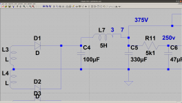
Here is an example. You must wire exactly as drawn on the schematic: one wire from the center tap to the first cap, from it another wire goes from the second cap, and from the second cap you can power the rest, it is the ground reference point. May be for the incandescent lamp all ground wires are electrically equal, anyway it will produce the light, but in sensitive equipment they are not, they have resistance, and currents that flow through them cause on them voltage drops that being added to weak signals cause hum and even HF oscillations due to feedback!
Thanks for that explanation.
Now, since the builder is dealing with a PCB......
Perhaps you could suggest a good spot to solder a wire from the chassis to the PCB, please.


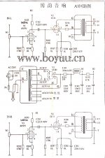
Judging by the original scheme of the A9 amplifier, the transformer screen winding is absent and not grounded.Assuming your PT has no shield lead:
The PT body is grounded to the chassis via the bolt where you have connected the 'green' AC safety wire
The circuit also does not indicate that the transformer housing is connected to the common wire.
Most likely, the author of the scheme united the earth with a common wire.
Those. the amplifier chassis is grounded.
This is valid if the chassis of the amplifier is colored and is not a conductor.
The A10 amplifier has a bare metal and cannot be used as a ground.
Location Proper connection of the common wire between all components of the amplifier is the key to its good work.
Attachments
Last edited:
Back to the drawing board. See: YouTube
Another attempt in attempt to troubleshoot: YouTube
Should have mentioned that I am using a 60 watt bulb in my DBT. I am not sure of power consumption on this amp (not much reliable info on this bad boy out there IMHO) so should I bump up to a 100 Watt bulb. The unit seems to operate well on power up. It strats up bright and then draws down shortly after. With both channels it just stays bright....
Tim-
It's difficult to tell how bright the bulb really is in a video.
If you have a short problem in the amp, the bulb will be as bright as it is in a standard lamp - i.e. normally bright.
Don't expect the lamp to 'go out' completely if the amp is working properly - don't forget that the amp and the bulb are 'sharing' the 120v AC supply (series connection).
You can see this if you operate a working amp through the dim bulb tester.
I'd be inclined to carry on, since the bulb is not full brightness, but as I said it is hard to tell from the video.
Do you have those sacrificial speakers handy?
- Home
- Amplifiers
- Tubes / Valves
- Boyuu EL34 A9 Tube Amp