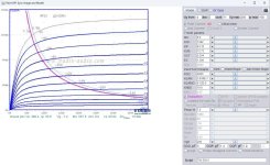
I manage to simulate these Ayumi spice models for 47 tube.Hi
I need a little help
Could someone run spice models for 47 in LTspice
to plot the characteristics?
Please?
It was a bit hard to get trough LT spice MAC OSX version... 🙁
Where to put sybols files, where to put spice model files, how to remark inside lines of symbols to accept spice models, etc..
.
I will explain later, in details HOW-TO for potential LTspice mac osx users to not spent whole afternoon in vain...
.
The models are not bad, but not so accurate against 47 General electric graph.
.
Problem is that i think that only one graph of anode chrs are existing in all datas... 🙁
.
Last edited:

spice model for 47 pentode (with tools soft)
.

.
Code:
**** 47_pentode ******************************************
* Created on 04/26/2025 17:19 using paint_kip.jar
* www.dmitrynizh.com/tubeparams_image.htm
* Plate Curves image file: 47 pentode chrs
* Data source link: 47 General Electric datas
* Model made by @Zoran DIY Audio member
*----------------------------------------------------------------------------------
* .SUBCKT  47_pentode P G2 G K ; LTSpice tetrode.asy pinout
.SUBCKT  47_pentode P G K G2 ; Koren Pentode Pspice pinout
+ PARAMS:
+ MU=8.62
+ KG1=2555.3
+ KP=67
+ KVB=12
+ VCT=0
+ EX=1.34
+ KG2=4200
+ KNEE=10.98
+ KVC=2.57
+ KLAM=3.96E-7
+ KLAMG=2.925E-5
+ KD=0.8335
+ KC=0.07392
+ KR1=1.267E-4
+ KR2=0.1691
+ KVBG=0.01219
+ KB1=1.96
+ KB2=1.511
+ KB3=1.89
+ KB4=0.4739
+ KVBGI=0.001
+ KNK=-0.00966
+ KNG=0.00325
+ KNPL=3.03
+ KNSL=0.2992
+ KNPR=123.55
+ KNSR=31.32
+ CCG=8.6P
+ CGP=1.2P
+ CCP=13P
+ RGI=2000.0
*----------------------------------------------------------------------------------
* Vp_MAX=500 Ip_MAX=100 Vg_step=4 Vg_start=0 Vg_count=9
* X_MIN=76 Y_MIN=42 X_SIZE=748 Y_SIZE=600 FSZ_X=1620 FSZ_Y=813 XYGrid=true
* Rp=7000 Vg_ac=15.3 P_max=8 Vg_qui=-15.3 Vp_qui=250
* showLoadLine=y showIp=y isDHP=n isPP=n isAsymPP=n isUL=n showDissipLimit=y
* showIg1=n isInputSnapped=n addLocalNFB=n
* XYProjections=y harmonicPlot=y dissipPlot=y
* UL=0.43 EG2=250 gridLevel2=n addKink=y isTanhKnee=n advSigmoid=y
*----------------------------------------------------------------------------------
RE1  7 0  1G    ; DUMMY SO NODE 7 HAS 2 CONNECTIONS
E1   7 0  VALUE=  ; E1 BREAKS UP LONG EQUATION FOR G1.
+{V(G2,K)/KP*LOG(1+EXP((1/MU+(VCT+V(G,K))/SQRT(KVB+V(G2,K)*V(G2,K)))*KP))}
RE2  6 0  1G    ; DUMMY SO NODE 6 HAS 2 CONNECTIONS
E2   6 0  VALUE={(PWR(V(7),EX)+PWRS(V(7),EX))} ; Kg1 times KIT current
E4   8 0  VALUE={V(P,K)/KNEE/(KVBGI+V(6)*KVBG)}
E5  81 0  VALUE={PWR(V(8),KB1)}
E6  82 0  VALUE={PWR(V(8),KB2)}
E7  83 0  VALUE={PWR(V(8),KB3)}
E8   9 0  VALUE={PWR(1-EXP(-V(81)*(KC+KR1*V(82))/(KD+KR2*V(83))),KB4)*1.5708}
RE4  8 0  1
RE5 81 0  1
RE6 82 0  1
RE7 83 0  1
RE8  9 0  1
RE21 21 0 1
E21  21 0 VALUE={V(6)/KG1*V(9)} ; Ip with knee but no slope and no kink
RE22 22 0 1 ; E22: kink curr deviation for plate
E22  22 0 VALUE={V(21)*LIMIT(KNK-V(G,K)*KNG,0,0.3)*(-ATAN((V(P,K)-KNPL)/KNSL)+ATAN((V(P,K)-KNPR)/KNSR))}
G1   P K  VALUE={V(21)*(1+KLAMG*V(P,K))+KLAM*V(P,K) + V(22)}
G2   G2 K  VALUE={V(6)/KG2*(KVC-V(9))/(1+KLAMG*V(P,K)) - V(22)}
RCP  P K  1G     ; FOR CONVERGENCE
C1   K G  {CCG}  ; CATHODE-GRID 1
C2   G P  {CGP}  ; GRID 1-PLATE
C3   K P  {CCP}  ; CATHODE-PLATE
R1   G 5  {RGI}  ; FOR GRID CURRENT
D3   5 K  DX     ; FOR GRID CURRENT }
.MODEL DX D(IS=1N RS=1 CJO=10PF TT=1N)
.ENDS 47_pentode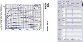
*$PL38 SPICE MODELS.
Code:
**** PL38 ******************************************
* Created on 04/29/2025 17:26 using paint_kip.jar
* www.dmitrynizh.com/tubeparams_image.htm
* Plate Curves image file: PL38.jpg
* Data source link: <plate curves URL>
*----------------------------------------------------------------------------------
.SUBCKT PL38 P G2 G K ; LTSpice tetrode.asy pinout
* .SUBCKT PL38 P G K G2 ; Koren Pentode Pspice pinout
+ PARAMS: MU=18 KG1=572 KP=108.12 KVB=12 VCT=0.568 EX=1.4 KG2=4200 KNEE=10.88 KVC=2.57
+ KLAM=1.944E-5 KLAMG=4.41E-4   KNK=-0.101 KNG=0.00582 KNPL=49.5 KNSL=11.22 KNPR=121.2 KNSR=30.45
+ CCG=18P CGP=1.2P CCP=6.5P RGI=2000.0
* Vp_MAX=400 Ip_MAX=150 Vg_step=2 Vg_start=0 Vg_count=7
* X_MIN=100 Y_MIN=126 X_SIZE=459 Y_SIZE=343 FSZ_X=1351 FSZ_Y=716 XYGrid=false
* Rp=1400 Vg_ac=20 P_max=25 Vg_qui=-6 Vp_qui=300
* showLoadLine=n showIp=y isDHP=n isPP=n isAsymPP=n isUL=n showDissipLimit=y
* showIg1=n isInputSnapped=y addLocalNFB=n
* XYProjections=n harmonicPlot=y dissipPlot=n
* UL=0.43 EG2=175 gridLevel2=n addKink=y isTanhKnee=n advSigmoid=n
*----------------------------------------------------------------------------------
RE1  7 0  1G    ; DUMMY SO NODE 7 HAS 2 CONNECTIONS
E1   7 0  VALUE=  ; E1 BREAKS UP LONG EQUATION FOR G1.
+{V(G2,K)/KP*LOG(1+EXP((1/MU+(VCT+V(G,K))/SQRT(KVB+V(G2,K)*V(G2,K)))*KP))}
RE2  6 0  1G    ; DUMMY SO NODE 6 HAS 2 CONNECTIONS
E2  6 0  VALUE={(PWR(V(7),EX)+PWRS(V(7),EX))} ; Kg1 times KIT current
RE21 21 0 1
E21  21 0 VALUE={V(6)/KG1*ATAN(V(P,K)/KNEE)} ; Ip with knee but no slope and no kink
RE22 22 0 1 ; E22: kink curr deviation for plate
E22  22 0 VALUE={V(21)*LIMIT(KNK-V(G,K)*KNG,0,0.3)*(-ATAN((V(P,K)-KNPL)/KNSL)+ATAN((V(P,K)-KNPR)/KNSR))}
G1   P  K  VALUE={V(21)*(1+KLAMG*V(P,K))+KLAM*V(P,K) + V(22)}
* Alexander Gurskii screen current, see audioXpress 2/2011, with slope and kink added
RE43 43 K 1G ; Dummy
E43  43 G2 VALUE={0} ; Dummy
G2   43 K  VALUE={V(6)/KG2*(KVC-ATAN(V(P,K)/KNEE))/(1+KLAMG*V(P,K))-V(22)}
RCP  P K  1G     ; FOR CONVERGENCE
C1   K G  {CCG}  ; CATHODE-GRID 1
C2   G P  {CGP}  ; GRID 1-PLATE
C3   K P  {CCP}  ; CATHODE-PLATE
R1   G 5  {RGI}  ; FOR GRID CURRENT
D3   5 K  DX     ; FOR GRID CURRENT }
.MODEL DX D(IS=1N RS=1 CJO=10PF TT=1N)
.ENDS
*$


* The following triode model is derived from pentode model, see above.
* In the triode model, all spice parameters come directly from the pentode model, except for Kg1,
* which for triode-strapped pentodes is derived from pentode's Kg1, Kg2 and Kvc as
*
*    4Kg1Kg2 / ((2Kvc-Pi)(2Kg1+PiKg2))

**** PL38 ******************************************
* Created on 04/29/2025 17:26 using paint_kit.jar 4.7
* www.dmitrynizh.com/tubeparams_image.htm
* Plate Curves image file: PL38.jpg
* Data source link: <plate curves URL>
*----------------------------------------------------------------------------------
.SUBCKT TRIODE_PL38 1 2 3 ; Plate Grid Cathode
+ PARAMS: CCG=18P  CGP=1.2P CCP=6.5P RGI=2000
+ MU=18 KG1=335.36 KP=108.12 KVB=12 VCT=0.568 EX=1.4
* Vp_MAX=400 Ip_MAX=150 Vg_step=2 Vg_start=0 Vg_count=7
* Rp=1400 Vg_ac=20 P_max=25 Vg_qui=-6 Vp_qui=300
* X_MIN=100 Y_MIN=126 X_SIZE=459 Y_SIZE=343 FSZ_X=1351 FSZ_Y=716 XYGrid=false
* showLoadLine=n showIp=y isDHT=n isPP=n isAsymPP=n showDissipLimit=y
* showIg1=n gridLevel2=n isInputSnapped=y
* XYProjections=n harmonicPlot=y dissipPlot=n
*----------------------------------------------------------------------------------
E1 7 0 VALUE={V(1,3)/KP*LOG(1+EXP(KP*(1/MU+(VCT+V(2,3))/SQRT(KVB+V(1,3)*V(1,3)))))}
RE1 7 0 1G  ; TO AVOID FLOATING NODES
G1 1 3 VALUE={(PWR(V(7),EX)+PWRS(V(7),EX))/KG1}
RCP 1 3 1G   ; TO AVOID FLOATING NODES
C1 2 3 {CCG} ; CATHODE-GRID
C2 2 1 {CGP} ; GRID=PLATE
C3 1 3 {CCP} ; CATHODE-PLATE
D3 5 3 DX ; POSITIVE GRID CURRENT
R1 2 5 {RGI} ; POSITIVE GRID CURRENT
.MODEL DX D(IS=1N RS=1 CJO=10PF TT=1N)
.ENDS
*$
Attachments
Hello.
I'm looking for the characteristics of the GU19-1/QQV06-40 tube in triode.
Thanks.
Piter
I'm looking for the characteristics of the GU19-1/QQV06-40 tube in triode.
Thanks.
Piter
6N13C_T SPICE MODELS.
Code:
**** 6N13C_T******************************************
* Created on 05/03/2025 11:15 using paint_kit.jar 3.1
* www.dmitrynizh.com/tubeparams_image.htm
* Plate Curves image file: 6N13C_T.jpg
* Data source link:
*----------------------------------------------------------------------------------
.SUBCKT TRIODE_6N13C_T 1 2 3 ; Plate Grid Cathode
+ PARAMS: CCG=3P  CGP=1.4P CCP=1.9P RGI=2000
+ MU=8.4 KG1=420 KP=44 KVB=654 VCT=0.328 EX=1.414
* Vp_MAX=350 Ip_MAX=200 Vg_step=5 Vg_start=0 Vg_count=11
* Rp=4000 Vg_ac=55 P_max=11 Vg_qui=-48 Vp_qui=300
* X_MIN=135 Y_MIN=268 X_SIZE=462 Y_SIZE=520 FSZ_X=1228 FSZ_Y=1100 XYGrid=false
* showLoadLine=n showIp=y isDHT=n isPP=n isAsymPP=n showDissipLimit=y
* showIg1=n gridLevel2=n isInputSnapped=n
* XYProjections=n harmonicPlot=n dissipPlot=n
*----------------------------------------------------------------------------------
E1 7 0 VALUE={V(1,3)/KP*LOG(1+EXP(KP*(1/MU+(VCT+V(2,3))/SQRT(KVB+V(1,3)*V(1,3)))))}
RE1 7 0 1G  ; TO AVOID FLOATING NODES
G1 1 3 VALUE={(PWR(V(7),EX)+PWRS(V(7),EX))/KG1}
RCP 1 3 1G   ; TO AVOID FLOATING NODES
C1 2 3 {CCG} ; CATHODE-GRID
C2 2 1 {CGP} ; GRID=PLATE
C3 1 3 {CCP} ; CATHODE-PLATE
D3 5 3 DX ; POSITIVE GRID CURRENT
R1 2 5 {RGI} ; POSITIVE GRID CURRENT
.MODEL DX D(IS=1N RS=1 CJO=10PF TT=1N)
.ENDS
*$
Attachments
Last edited:
Hi I made quick models for GU19-1 for Ug2=200V and 250VHello.
I'm looking for the characteristics of the GU19-1/QQV06-40 tube in triode.
Thanks.
Piter
Maybe they not so accurate but it is good starting point?
(
Models are for LTspice,
.SUBCKT GU19-1_200 P G2 G K ; LTSpice tetrode.asy pinout
* .SUBCKT GU19-1_200 P G K G2 ; Koren Pentode Pspice pinout
.
for PSpice ucomment LT spice lines and activate for PSpice
* .SUBCKT GU19-1_200 P G2 G K ; LTSpice tetrode.asy pinout
*.SUBCKT GU19-1_200 P G K G2 ; Koren Pentode Pspice pinout
)
Code:
*  GU19-1 Ug2=200V
 ****  ******************************************
* Created on 05/03/2025 10:42 using paint_kip.jar
* www.dmitrynizh.com/tubeparams_image.htm
* Plate Curves image file: /Users/zoran/Desktop/Model_Paint_Tools/Graph/
* Data source link: <plate curves URL>
*----------------------------------------------------------------------------------
.SUBCKT GU19-1_200 P G2 G K ; LTSpice tetrode.asy pinout
* .SUBCKT GU19-1_200 P G K G2 ; Koren Pentode Pspice pinout
+ PARAMS: MU=9.6 KG1=1088.34 KP=32.28 KVB=12 VCT=0.324 EX=1.4 KG2=4200 KNEE=23.35 KVC=2.57
+ KLAM=2.24E-6 KLAMG=3.788E-6 KNEE2=46.87 KNEX=32.4  KNK=-0.1168 KNG=0.01302 KNPL=33 KNSL=16.5 KNPR=129.6 KNSR=30.45
+ CCG=10P CGP=1.5P CCP=3.5P RGI=2000.0
* Vp_MAX=600 Ip_MAX=320 Vg_step=5 Vg_start=10 Vg_count=8
* X_MIN=122 Y_MIN=44 X_SIZE=786 Y_SIZE=524 FSZ_X=1372 FSZ_Y=703 XYGrid=true
* Rp=2400 Vg_ac=10 P_max=20 Vg_qui=-10 Vp_qui=200
* showLoadLine=n showIp=y isDHP=n isPP=n isAsymPP=n isUL=n showDissipLimit=y
* showIg1=n isInputSnapped=n addLocalNFB=n
* XYProjections=y harmonicPlot=y dissipPlot=y
* UL=0.43 EG2=200 gridLevel2=n addKink=y isTanhKnee=y advSigmoid=n
*----------------------------------------------------------------------------------
RE1  7 0  1G    ; DUMMY SO NODE 7 HAS 2 CONNECTIONS
E1   7 0  VALUE=  ; E1 BREAKS UP LONG EQUATION FOR G1.
+{V(G2,K)/KP*LOG(1+EXP((1/MU+(VCT+V(G,K))/SQRT(KVB+V(G2,K)*V(G2,K)))*KP))}
RE2  6 0  1G    ; DUMMY SO NODE 6 HAS 2 CONNECTIONS
E2  6 0  VALUE={(PWR(V(7),EX)+PWRS(V(7),EX))} ; Kg1 times KIT current
RE21 21 0 1
E21  21 0 VALUE={V(6)/KG1*ATAN((V(P,K)+KNEX)/KNEE)*TANH(V(P,K)/KNEE2)} ; Ip with knee but no slope and no kink
RE22 22 0 1 ; E22: kink curr deviation for plate
E22  22 0 VALUE={V(21)*LIMIT(KNK-V(G,K)*KNG,0,0.3)*(-ATAN((V(P,K)-KNPL)/KNSL)+ATAN((V(P,K)-KNPR)/KNSR))}
G1   P  K  VALUE={V(21)*(1+KLAMG*V(P,K))+KLAM*V(P,K) + V(22)}
* Alexander Gurskii screen current, see audioXpress 2/2011, with slope and kink added
RE43 43 K 1G ; Dummy
E43  43 G2 VALUE={0} ; Dummy
G2   43 K  VALUE={V(6)/KG2*(KVC-ATAN((V(P,K)+KNEX)/KNEE)*TANH(V(P,K)/KNEE2))/(1+KLAMG*V(P,K))-V(22)}
RCP  P K  1G     ; FOR CONVERGENCE
C1   K G  {CCG}  ; CATHODE-GRID 1
C2   G P  {CGP}  ; GRID 1-PLATE
C3   K P  {CCP}  ; CATHODE-PLATE
R1   G 5  {RGI}  ; FOR GRID CURRENT
D3   5 K  DX     ; FOR GRID CURRENT }
.MODEL DX D(IS=1N RS=1 CJO=10PF TT=1N)
.ENDS GU19-1_200
*$


* The following triode model is derived from pentode model, see above.
* In the triode model, all spice parameters come directly from the pentode model, except for Kg1,
* which for triode-strapped pentodes is derived from pentode's Kg1, Kg2 and Kvc as
*
*    4Kg1Kg2 / ((2Kvc-Pi)(2Kg1+PiKg2))
*
****  ******************************************
* Created on 05/03/2025 10:42 using paint_kit.jar 4.7
* www.dmitrynizh.com/tubeparams_image.htm
* Plate Curves image file: /Users/zoran/Desktop/Model_Paint_Tools/Graph/
* Data source link: <plate curves URL>
*----------------------------------------------------------------------------------
.SUBCKT GU19-1_200_T 1 2 3 ; Plate Grid Cathode
+ PARAMS: CCG=10P  CGP=1.5P CCP=3.5P RGI=2000
+ MU=9.6 KG1=595.22 KP=32.28 KVB=12 VCT=0.324 EX=1.4
* Vp_MAX=600 Ip_MAX=320 Vg_step=5 Vg_start=10 Vg_count=8
* Rp=2400 Vg_ac=10 P_max=20 Vg_qui=-10 Vp_qui=200
* X_MIN=122 Y_MIN=44 X_SIZE=786 Y_SIZE=524 FSZ_X=1372 FSZ_Y=703 XYGrid=true
* showLoadLine=n showIp=y isDHT=n isPP=n isAsymPP=n showDissipLimit=y
* showIg1=n gridLevel2=n isInputSnapped=n
* XYProjections=y harmonicPlot=y dissipPlot=y
*----------------------------------------------------------------------------------
E1 7 0 VALUE={V(1,3)/KP*LOG(1+EXP(KP*(1/MU+(VCT+V(2,3))/SQRT(KVB+V(1,3)*V(1,3)))))}
RE1 7 0 1G  ; TO AVOID FLOATING NODES
G1 1 3 VALUE={(PWR(V(7),EX)+PWRS(V(7),EX))/KG1}
RCP 1 3 1G   ; TO AVOID FLOATING NODES
C1 2 3 {CCG} ; CATHODE-GRID
C2 2 1 {CGP} ; GRID=PLATE
C3 1 3 {CCP} ; CATHODE-PLATE
D3 5 3 DX ; POSITIVE GRID CURRENT
R1 2 5 {RGI} ; POSITIVE GRID CURRENT
.MODEL DX D(IS=1N RS=1 CJO=10PF TT=1N)
.ENDS GU19-1_200_T
*$


*  GU19-1 Ug2=200V
****  ******************************************
* Created on 05/03/2025 10:50 using paint_kip.jar
* www.dmitrynizh.com/tubeparams_image.htm
* Plate Curves image file: /Users/zoran/Desktop/Model_Paint_Tools/Graph/
* Data source link: <plate curves URL>
*----------------------------------------------------------------------------------
.SUBCKT GU19-1_250 P G2 G K ; LTSpice tetrode.asy pinout
* .SUBCKT  P G K G2 ; Koren Pentode Pspice pinout
+ PARAMS: MU=12.5 KG1=1391.28 KP=95.67 KVB=12 VCT=0.05 EX=1.428 KG2=4200 KNEE=23.35 KVC=2.57
+ KLAM=2.262E-6 KLAMG=3.788E-6 KNEE2=42.65 KNEX=43.8  KNK=-0.1168 KNG=0.01302 KNPL=30 KNSL=15.18 KNPR=129.6 KNSR=29
+ CCG=10P CGP=1.5P CCP=3.5P RGI=2000.0
* Vp_MAX=600 Ip_MAX=320 Vg_step=5 Vg_start=10 Vg_count=7
* X_MIN=122 Y_MIN=44 X_SIZE=786 Y_SIZE=524 FSZ_X=1372 FSZ_Y=703 XYGrid=true
* Rp=2400 Vg_ac=10 P_max=20 Vg_qui=-10 Vp_qui=200
* showLoadLine=n showIp=y isDHP=n isPP=n isAsymPP=n isUL=n showDissipLimit=y
* showIg1=n isInputSnapped=n addLocalNFB=n
* XYProjections=y harmonicPlot=y dissipPlot=y
* UL=0.43 EG2=250 gridLevel2=n addKink=y isTanhKnee=y advSigmoid=n
*----------------------------------------------------------------------------------
RE1  7 0  1G    ; DUMMY SO NODE 7 HAS 2 CONNECTIONS
E1   7 0  VALUE=  ; E1 BREAKS UP LONG EQUATION FOR G1.
+{V(G2,K)/KP*LOG(1+EXP((1/MU+(VCT+V(G,K))/SQRT(KVB+V(G2,K)*V(G2,K)))*KP))}
RE2  6 0  1G    ; DUMMY SO NODE 6 HAS 2 CONNECTIONS
E2  6 0  VALUE={(PWR(V(7),EX)+PWRS(V(7),EX))} ; Kg1 times KIT current
RE21 21 0 1
E21  21 0 VALUE={V(6)/KG1*ATAN((V(P,K)+KNEX)/KNEE)*TANH(V(P,K)/KNEE2)} ; Ip with knee but no slope and no kink
RE22 22 0 1 ; E22: kink curr deviation for plate
E22  22 0 VALUE={V(21)*LIMIT(KNK-V(G,K)*KNG,0,0.3)*(-ATAN((V(P,K)-KNPL)/KNSL)+ATAN((V(P,K)-KNPR)/KNSR))}
G1   P  K  VALUE={V(21)*(1+KLAMG*V(P,K))+KLAM*V(P,K) + V(22)}
* Alexander Gurskii screen current, see audioXpress 2/2011, with slope and kink added
RE43 43 K 1G ; Dummy
E43  43 G2 VALUE={0} ; Dummy
G2   43 K  VALUE={V(6)/KG2*(KVC-ATAN((V(P,K)+KNEX)/KNEE)*TANH(V(P,K)/KNEE2))/(1+KLAMG*V(P,K))-V(22)}
RCP  P K  1G     ; FOR CONVERGENCE
C1   K G  {CCG}  ; CATHODE-GRID 1
C2   G P  {CGP}  ; GRID 1-PLATE
C3   K P  {CCP}  ; CATHODE-PLATE
R1   G 5  {RGI}  ; FOR GRID CURRENT
D3   5 K  DX     ; FOR GRID CURRENT }
.MODEL DX D(IS=1N RS=1 CJO=10PF TT=1N)
.ENDS GU19-1_250
*$


* The following triode model is derived from pentode model, see above.
* In the triode model, all spice parameters come directly from the pentode model, except for Kg1,
* which for triode-strapped pentodes is derived from pentode's Kg1, Kg2 and Kvc as
*
*    4Kg1Kg2 / ((2Kvc-Pi)(2Kg1+PiKg2))
*
****  ******************************************
* Created on 05/03/2025 10:50 using paint_kit.jar 4.7
* www.dmitrynizh.com/tubeparams_image.htm
* Plate Curves image file: /Users/zoran/Desktop/Model_Paint_Tools/Graph/
* Data source link: <plate curves URL>
*----------------------------------------------------------------------------------
.SUBCKT GU19-1_250_T 1 2 3 ; Plate Grid Cathode
+ PARAMS: CCG=10P  CGP=1.5P CCP=3.5P RGI=2000
+ MU=12.5 KG1=732.05 KP=95.67 KVB=12 VCT=0.05 EX=1.428
* Vp_MAX=600 Ip_MAX=320 Vg_step=5 Vg_start=10 Vg_count=7
* Rp=2400 Vg_ac=10 P_max=20 Vg_qui=-10 Vp_qui=200
* X_MIN=122 Y_MIN=44 X_SIZE=786 Y_SIZE=524 FSZ_X=1372 FSZ_Y=703 XYGrid=true
* showLoadLine=n showIp=y isDHT=n isPP=n isAsymPP=n showDissipLimit=y
* showIg1=n gridLevel2=n isInputSnapped=n
* XYProjections=y harmonicPlot=y dissipPlot=y
*----------------------------------------------------------------------------------
E1 7 0 VALUE={V(1,3)/KP*LOG(1+EXP(KP*(1/MU+(VCT+V(2,3))/SQRT(KVB+V(1,3)*V(1,3)))))}
RE1 7 0 1G  ; TO AVOID FLOATING NODES
G1 1 3 VALUE={(PWR(V(7),EX)+PWRS(V(7),EX))/KG1}
RCP 1 3 1G   ; TO AVOID FLOATING NODES
C1 2 3 {CCG} ; CATHODE-GRID
C2 2 1 {CGP} ; GRID=PLATE
C3 1 3 {CCP} ; CATHODE-PLATE
D3 5 3 DX ; POSITIVE GRID CURRENT
R1 2 5 {RGI} ; POSITIVE GRID CURRENT
.MODEL DX D(IS=1N RS=1 CJO=10PF TT=1N)
.ENDS GU19-1_250_T
*$
Last edited:
Thanks for the models, but they are not very accurate for my purposes, I will have to buy them and download the characteristics.
Thanks.
Piter
Thanks.
Piter
If i found some time I can extract points from these 2 graphs and load them into the MatLab sheet (Norman K. version) to try to find mode accurate model for the tube.
.
These 2 are also acurate BUT for specific Ug2=200V and Ug2=250V
constant 2 values only...
.
These 2 are also acurate BUT for specific Ug2=200V and Ug2=250V
constant 2 values only...
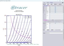
RCA-50 and UX-250 triode spice model
.
I spot that is no models for beautiful old-school-hard-to-find triode RCA-50, and UX-250
types and their equivalents.
I found that these two types are still a slight different, when graphs of anode chrs are compared.
.

.

.
Sorry that I didnt wrote on the graph picture...
Red=old RCA-50 PDF
Orange=newer RCA-50 PDF
Black=UX-250 from some PDF examining the tube. With 2 values of heating voltage
Blue=some measurement of 50 from internet
.
We see that old and newer 50-RCA Uf=7.5V graphs are the same, and somehow tent to UX-250 curves BUT with Uf=7V
.
(But I must note that Ri and Req a bit higher more than 1200 ohms, so the output transformer has to be Henry-s heavy for decent bass response...)
.
There are 2 models for each type, one DHT, other standard triode without DHT conn much more commonly in use. 6 spice models total
cheers
.
.
I spot that is no models for beautiful old-school-hard-to-find triode RCA-50, and UX-250
types and their equivalents.
I found that these two types are still a slight different, when graphs of anode chrs are compared.
.
.
.
Sorry that I didnt wrote on the graph picture...
Red=old RCA-50 PDF
Orange=newer RCA-50 PDF
Black=UX-250 from some PDF examining the tube. With 2 values of heating voltage
Blue=some measurement of 50 from internet
.
We see that old and newer 50-RCA Uf=7.5V graphs are the same, and somehow tent to UX-250 curves BUT with Uf=7V
.
(But I must note that Ri and Req a bit higher more than 1200 ohms, so the output transformer has to be Henry-s heavy for decent bass response...)
.
There are 2 models for each type, one DHT, other standard triode without DHT conn much more commonly in use. 6 spice models total
cheers
.
Attachments
Last edited:
Zoran
What circuit do you use to test the valves in LTSpice to get these curves? I want to do the same with the 2A3s.
thanx!
What circuit do you use to test the valves in LTSpice to get these curves? I want to do the same with the 2A3s.
thanx!
With this simple circuit for RCA-50 (old PDF graph anode characteristic used for Spice model)What circuit do you use to test the valves in LTSpice to get these curves? I want to do the same with the 2A3s.
.
I put in the post 2A3 sch with model of RCA version i made with MatLab, very precise...
You can use any of these LT spice files to print the curves of triode models.
Just
copy and paste spice model in the LT directive
change name of the tube must be same as in the spice model
cgange the name inside the symbol
Change the parameters of Vmax and -Ug in the spice directive
Attachments
Please do, I am just getting started with LT Spice via kicad on my M2 Max.I manage to simulate these Ayumi spice models for 47 tube.
It was a bit hard to get trough LT spice MAC OSX version... 🙁
Where to put sybols files, where to put spice model files, how to remark inside lines of symbols to accept spice models, etc..
.
I will explain later, in details HOW-TO for potential LTspice mac osx users to not spent whole afternoon in vain...
.
Has anyone seen any different KT-77 models? I've seen the ayumi ones, including the triode-mode specific one, and neither one is remotely close to the curves audiomatica has: https://www.audiomatica.com/tubes/kt77.htm
And I think at least smoking_amp said that the audiomatica curves are pretty close to the current production JJ KT-77's, for example. The ayumi models have like half the plate current in triode mode. eg, 375v, -28v is around 66-70mA on those graphs, but the ayumi model is like 36mA, which is closer to what the old Genalex datasheet curves show. It's not clear to me what brand the KT-77 that audiomatica shows. vtadiy's curves are based on the ayumi model.
Setting aside the 'which is the true KT-77', just curious if anyone has seen anything close to these higher-current curves or has any suggestions.
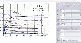
THE CHINA 6J9 SPICE MODELS.
Code:
**** 6J9_CH ******************************************
* Created on 05/19/2025 10:25 using paint_kip.jar
* www.dmitrynizh.com/tubeparams_image.htm
* Plate Curves image file: 6J9_3.jpg
* Data source link: <plate curves URL>
*----------------------------------------------------------------------------------
.SUBCKT 6J9_CH P G2 G K ; LTSpice tetrode.asy pinout
* .SUBCKT 6J9_3 P G K G2 ; Koren Pentode Pspice pinout
+ PARAMS: MU=59.6 KG1=220 KP=364.89 KVB=11.28 VCT=0.066 EX=1.4 KG2=4200 KNEE=4.618 KVC=2.57
+ KLAM=2.375E-8 KLAMG=1.013E-6 KNEE2=8.979 KNEX=0.93  KNK=-0.0997 KNG=0.00294 KNPL=47.5 KNSL=10.23 KNPR=121.2 KNSR=29.87
+ CCG=8.5P CGP=0.03P CCP=3.1P RGI=2000.0
* Vp_MAX=250 Ip_MAX=60 Vg_step=0.5 Vg_start=0 Vg_count=6
* X_MIN=56 Y_MIN=200 X_SIZE=559 Y_SIZE=334 FSZ_X=1330 FSZ_Y=723 XYGrid=false
* Rp=1400 Vg_ac=20 P_max=3 Vg_qui=-1.25 Vp_qui=300
* showLoadLine=n showIp=y isDHP=n isPP=n isAsymPP=n isUL=n showDissipLimit=y
* showIg1=n isInputSnapped=y addLocalNFB=n
* XYProjections=n harmonicPlot=y dissipPlot=n
* UL=0.43 EG2=150 gridLevel2=n addKink=y isTanhKnee=y advSigmoid=n
*----------------------------------------------------------------------------------
RE1  7 0  1G    ; DUMMY SO NODE 7 HAS 2 CONNECTIONS
E1   7 0  VALUE=  ; E1 BREAKS UP LONG EQUATION FOR G1.
+{V(G2,K)/KP*LOG(1+EXP((1/MU+(VCT+V(G,K))/SQRT(KVB+V(G2,K)*V(G2,K)))*KP))}
RE2  6 0  1G    ; DUMMY SO NODE 6 HAS 2 CONNECTIONS
E2  6 0  VALUE={(PWR(V(7),EX)+PWRS(V(7),EX))} ; Kg1 times KIT current
RE21 21 0 1
E21  21 0 VALUE={V(6)/KG1*ATAN((V(P,K)+KNEX)/KNEE)*TANH(V(P,K)/KNEE2)} ; Ip with knee but no slope and no kink
RE22 22 0 1 ; E22: kink curr deviation for plate
E22  22 0 VALUE={V(21)*LIMIT(KNK-V(G,K)*KNG,0,0.3)*(-ATAN((V(P,K)-KNPL)/KNSL)+ATAN((V(P,K)-KNPR)/KNSR))}
G1   P  K  VALUE={V(21)*(1+KLAMG*V(P,K))+KLAM*V(P,K) + V(22)}
* Alexander Gurskii screen current, see audioXpress 2/2011, with slope and kink added
RE43 43 K 1G ; Dummy
E43  43 G2 VALUE={0} ; Dummy
G2   43 K  VALUE={V(6)/KG2*(KVC-ATAN((V(P,K)+KNEX)/KNEE)*TANH(V(P,K)/KNEE2))/(1+KLAMG*V(P,K))-V(22)}
RCP  P K  1G     ; FOR CONVERGENCE
C1   K G  {CCG}  ; CATHODE-GRID 1
C2   G P  {CGP}  ; GRID 1-PLATE
C3   K P  {CCP}  ; CATHODE-PLATE
R1   G 5  {RGI}  ; FOR GRID CURRENT
D3   5 K  DX     ; FOR GRID CURRENT }
.MODEL DX D(IS=1N RS=1 CJO=10PF TT=1N)
.ENDS
*$


* The following triode model is derived from pentode model, see above.
* In the triode model, all spice parameters come directly from the pentode model, except for Kg1,
* which for triode-strapped pentodes is derived from pentode's Kg1, Kg2 and Kvc as
*
*    4Kg1Kg2 / ((2Kvc-Pi)(2Kg1+PiKg2))

**** 6J9_3 ******************************************
* Created on 05/19/2025 10:25 using paint_kit.jar 4.7
* www.dmitrynizh.com/tubeparams_image.htm
* Plate Curves image file: 6J9_3.jpg
* Data source link: <plate curves URL>
*----------------------------------------------------------------------------------
.SUBCKT TRIODE_6J9_3 1 2 3 ; Plate Grid Cathode
+ PARAMS: CCG=8.5P  CGP=0.03P CCP=3.1P RGI=2000
+ MU=59.6 KG1=135.64 KP=364.89 KVB=11.28 VCT=0.066 EX=1.4
* Vp_MAX=250 Ip_MAX=60 Vg_step=0.5 Vg_start=0 Vg_count=6
* Rp=1400 Vg_ac=20 P_max=3 Vg_qui=-1.25 Vp_qui=300
* X_MIN=56 Y_MIN=200 X_SIZE=559 Y_SIZE=334 FSZ_X=1330 FSZ_Y=723 XYGrid=false
* showLoadLine=n showIp=y isDHT=n isPP=n isAsymPP=n showDissipLimit=y
* showIg1=n gridLevel2=n isInputSnapped=y
* XYProjections=n harmonicPlot=y dissipPlot=n
*----------------------------------------------------------------------------------
E1 7 0 VALUE={V(1,3)/KP*LOG(1+EXP(KP*(1/MU+(VCT+V(2,3))/SQRT(KVB+V(1,3)*V(1,3)))))}
RE1 7 0 1G  ; TO AVOID FLOATING NODES
G1 1 3 VALUE={(PWR(V(7),EX)+PWRS(V(7),EX))/KG1}
RCP 1 3 1G   ; TO AVOID FLOATING NODES
C1 2 3 {CCG} ; CATHODE-GRID
C2 2 1 {CGP} ; GRID=PLATE
C3 1 3 {CCP} ; CATHODE-PLATE
D3 5 3 DX ; POSITIVE GRID CURRENT
R1 2 5 {RGI} ; POSITIVE GRID CURRENT
.MODEL DX D(IS=1N RS=1 CJO=10PF TT=1N)
.ENDS
*$
Attachments
I am looking for a LTspice model for a EF92 6CQ6 and would appreciate it if anyone could supply a model.
Try this EF92 SPICE MODELS.
Code:
**** EF92 ******************************************
* Created on 05/22/2025 18:44 using paint_kip.jar
* www.dmitrynizh.com/tubeparams_image.htm
* Plate Curves image file: EF92.jpg
* Data source link: <plate curves URL>
*----------------------------------------------------------------------------------
.SUBCKT EF92 P G2 G K ; LTSpice tetrode.asy pinout
* .SUBCKT EF92 P G K G2 ; Koren Pentode Pspice pinout
+ PARAMS: MU=32.02 KG1=2635.58 KP=88.54 KVB=2.232 VCT=0.003 EX=1.4 KG2=4662 KNEE=9.48 KVC=2.57
+ KLAM=4.924E-9 KLAMG=5.104E-8   KNK=-0.4039 KNG=0.003
+ CCG=4.5P CGP=0.004P CCP=7P RGI=2000.0
* Vp_MAX=500 Ip_MAX=30 Vg_step=2 Vg_start=0 Vg_count=5
* X_MIN=39 Y_MIN=64 X_SIZE=565 Y_SIZE=349 FSZ_X=1242 FSZ_Y=733 XYGrid=false
* Rp=1400 Vg_ac=20 P_max=2.5 Vg_qui=-4 Vp_qui=300
* showLoadLine=n showIp=y isDHP=n isPP=n isAsymPP=n isUL=n showDissipLimit=y
* showIg1=n isInputSnapped=y addLocalNFB=n
* XYProjections=n harmonicPlot=y dissipPlot=n
* UL=0.43 EG2=250 gridLevel2=n addKink=n isTanhKnee=n advSigmoid=n
*----------------------------------------------------------------------------------
RE1  7 0  1G    ; DUMMY SO NODE 7 HAS 2 CONNECTIONS
E1   7 0  VALUE=  ; E1 BREAKS UP LONG EQUATION FOR G1.
+{V(G2,K)/KP*LOG(1+EXP((1/MU+(VCT+V(G,K))/SQRT(KVB+V(G2,K)*V(G2,K)))*KP))}
RE2  6 0  1G    ; DUMMY SO NODE 6 HAS 2 CONNECTIONS
E2  6 0  VALUE={(PWR(V(7),EX)+PWRS(V(7),EX))} ; Kg1 times KIT current
G1   P K  VALUE={V(6)/KG1*ATAN(V(P,K)/KNEE)*(1+KLAMG*V(P,K))+KLAM*V(P,K)}
* Alexander Gurskii screen current, see audioXpress 2/2011
RE4K 4K K 1G ; Dummy, per Alex request
E4K 4K  4 VALUE={0} ; Dummy, per Alex request
G4K 4K K VALUE={V(6)/KG2*(KVC-ATAN(V(P,K)/KNEE))/(1+KLAMG*V(P,K))}
RCP  P K  1G     ; FOR CONVERGENCE
C1   K G  {CCG}  ; CATHODE-GRID 1
C2   G P  {CGP}  ; GRID 1-PLATE
C3   K P  {CCP}  ; CATHODE-PLATE
R1   G 5  {RGI}  ; FOR GRID CURRENT
D3   5 K  DX     ; FOR GRID CURRENT }
.MODEL DX D(IS=1N RS=1 CJO=10PF TT=1N)
.ENDS
*$


* The following triode model is derived from pentode model, see above.
* In the triode model, all spice parameters come directly from the pentode model, except for Kg1,
* which for triode-strapped pentodes is derived from pentode's Kg1, Kg2 and Kvc as
*
*    4Kg1Kg2 / ((2Kvc-Pi)(2Kg1+PiKg2))

**** EF92 ******************************************
* Created on 05/22/2025 18:44 using paint_kit.jar 4.7
* www.dmitrynizh.com/tubeparams_image.htm
* Plate Curves image file: EF92.jpg
* Data source link: <plate curves URL>
*----------------------------------------------------------------------------------
.SUBCKT TRIODE_EF92 1 2 3 ; Plate Grid Cathode
+ PARAMS: CCG=4.5P  CGP=0.004P CCP=7P RGI=2000
+ MU=32.02 KG1=1234.8 KP=88.54 KVB=2.232 VCT=0.003 EX=1.4
* Vp_MAX=500 Ip_MAX=30 Vg_step=2 Vg_start=0 Vg_count=5
* Rp=1400 Vg_ac=20 P_max=2.5 Vg_qui=-4 Vp_qui=300
* X_MIN=39 Y_MIN=64 X_SIZE=565 Y_SIZE=349 FSZ_X=1242 FSZ_Y=733 XYGrid=false
* showLoadLine=n showIp=y isDHT=n isPP=n isAsymPP=n showDissipLimit=y
* showIg1=n gridLevel2=n isInputSnapped=y
* XYProjections=n harmonicPlot=y dissipPlot=n
*----------------------------------------------------------------------------------
E1 7 0 VALUE={V(1,3)/KP*LOG(1+EXP(KP*(1/MU+(VCT+V(2,3))/SQRT(KVB+V(1,3)*V(1,3)))))}
RE1 7 0 1G  ; TO AVOID FLOATING NODES
G1 1 3 VALUE={(PWR(V(7),EX)+PWRS(V(7),EX))/KG1}
RCP 1 3 1G   ; TO AVOID FLOATING NODES
C1 2 3 {CCG} ; CATHODE-GRID
C2 2 1 {CGP} ; GRID=PLATE
C3 1 3 {CCP} ; CATHODE-PLATE
D3 5 3 DX ; POSITIVE GRID CURRENT
R1 2 5 {RGI} ; POSITIVE GRID CURRENT
.MODEL DX D(IS=1N RS=1 CJO=10PF TT=1N)
.ENDS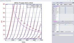
*$Chinese 4P1S electronic transistor triode connection method spice models.
Code:
**** 4P1S_T ******************************************
* Created on 05/23/2025 10:28 using paint_kit.jar 3.1
* www.dmitrynizh.com/tubeparams_image.htm
* Plate Curves image file: 4P1S_T.jpg
* Data source link:
*----------------------------------------------------------------------------------
.SUBCKT TRIODE_4P1S_T 1 2 3 ; Plate Grid Cathode
+ PARAMS: CCG=4P  CGP=0.007P CCP=4.2P RGI=2000
+ MU=9.74 KG1=1095 KP=102 KVB=159 VCT=3.125E-4 EX=1.555
* Vp_MAX=500 Ip_MAX=80 Vg_step=5 Vg_start=0 Vg_count=11
* Rp=4000 Vg_ac=55 P_max=7.5 Vg_qui=-48 Vp_qui=300
* X_MIN=107 Y_MIN=46 X_SIZE=646 Y_SIZE=630 FSZ_X=1357 FSZ_Y=790 XYGrid=false
* showLoadLine=n showIp=y isDHT=n isPP=n isAsymPP=n showDissipLimit=y
* showIg1=n gridLevel2=n isInputSnapped=n
* XYProjections=n harmonicPlot=n dissipPlot=n
*----------------------------------------------------------------------------------
E1 7 0 VALUE={V(1,3)/KP*LOG(1+EXP(KP*(1/MU+(VCT+V(2,3))/SQRT(KVB+V(1,3)*V(1,3)))))}
RE1 7 0 1G  ; TO AVOID FLOATING NODES
G1 1 3 VALUE={(PWR(V(7),EX)+PWRS(V(7),EX))/KG1}
RCP 1 3 1G   ; TO AVOID FLOATING NODES
C1 2 3 {CCG} ; CATHODE-GRID
C2 2 1 {CGP} ; GRID=PLATE
C3 1 3 {CCP} ; CATHODE-PLATE
D3 5 3 DX ; POSITIVE GRID CURRENT
R1 2 5 {RGI} ; POSITIVE GRID CURRENT
.MODEL DX D(IS=1N RS=1 CJO=10PF TT=1N)
.ENDS
*$
Attachments
Last edited:
Chinese 4P1S electronic transistore spice models.
Code:
**** 4P1S ******************************************
* Created on 05/23/2025 17:04 using paint_kip.jar
* www.dmitrynizh.com/tubeparams_image.htm
* Plate Curves image file: 4P1S.jpg
* Data source link: <plate curves URL>
*----------------------------------------------------------------------------------
.SUBCKT 4P1S P G2 G K ; LTSpice tetrode.asy pinout
* .SUBCKT 4P1S P G K G2 ; Koren Pentode Pspice pinout
+ PARAMS: MU=9.4 KG1=1342 KP=43.15 KVB=12.72 VCT=0.304 EX=1.386 KG2=4200 KNEE=19.8 KVC=2.57
+ KLAM=3.939E-7 KLAMG=6.12E-5   KNK=-0.044 KNG=0.006
+ CCG=3P CGP=1.4P CCP=1.9P RGI=2000.0
* Vp_MAX=400 Ip_MAX=160 Vg_step=2 Vg_start=-4 Vg_count=11
* X_MIN=46 Y_MIN=14 X_SIZE=633 Y_SIZE=462 FSZ_X=1253 FSZ_Y=775 XYGrid=false
* Rp=1400 Vg_ac=20 P_max=7.5 Vg_qui=-14 Vp_qui=300
* showLoadLine=n showIp=y isDHP=n isPP=n isAsymPP=n isUL=n showDissipLimit=y
* showIg1=n isInputSnapped=y addLocalNFB=n
* XYProjections=n harmonicPlot=y dissipPlot=n
* UL=0.43 EG2=200 gridLevel2=n addKink=n isTanhKnee=n advSigmoid=n
*----------------------------------------------------------------------------------
RE1  7 0  1G    ; DUMMY SO NODE 7 HAS 2 CONNECTIONS
E1   7 0  VALUE=  ; E1 BREAKS UP LONG EQUATION FOR G1.
+{V(G2,K)/KP*LOG(1+EXP((1/MU+(VCT+V(G,K))/SQRT(KVB+V(G2,K)*V(G2,K)))*KP))}
RE2  6 0  1G    ; DUMMY SO NODE 6 HAS 2 CONNECTIONS
E2  6 0  VALUE={(PWR(V(7),EX)+PWRS(V(7),EX))} ; Kg1 times KIT current
G1   P K  VALUE={V(6)/KG1*ATAN(V(P,K)/KNEE)*(1+KLAMG*V(P,K))+KLAM*V(P,K)}
* Alexander Gurskii screen current, see audioXpress 2/2011
RE4K 4K K 1G ; Dummy, per Alex request
E4K 4K  4 VALUE={0} ; Dummy, per Alex request
G4K 4K K VALUE={V(6)/KG2*(KVC-ATAN(V(P,K)/KNEE))/(1+KLAMG*V(P,K))}
RCP  P K  1G     ; FOR CONVERGENCE
C1   K G  {CCG}  ; CATHODE-GRID 1
C2   G P  {CGP}  ; GRID 1-PLATE
C3   K P  {CCP}  ; CATHODE-PLATE
R1   G 5  {RGI}  ; FOR GRID CURRENT
D3   5 K  DX     ; FOR GRID CURRENT }
.MODEL DX D(IS=1N RS=1 CJO=10PF TT=1N)
.ENDS
*$


* The following triode model is derived from pentode model, see above.
* In the triode model, all spice parameters come directly from the pentode model, except for Kg1,
* which for triode-strapped pentodes is derived from pentode's Kg1, Kg2 and Kvc as
*
*    4Kg1Kg2 / ((2Kvc-Pi)(2Kg1+PiKg2))

**** 4P1S ******************************************
* Created on 05/23/2025 17:04 using paint_kit.jar 4.7
* www.dmitrynizh.com/tubeparams_image.htm
* Plate Curves image file: 4P1S.jpg
* Data source link: <plate curves URL>
*----------------------------------------------------------------------------------
.SUBCKT TRIODE_4P1S 1 2 3 ; Plate Grid Cathode
+ PARAMS: CCG=3P  CGP=1.4P CCP=1.9P RGI=2000
+ MU=9.4 KG1=710.5 KP=43.15 KVB=12.72 VCT=0.304 EX=1.386
* Vp_MAX=400 Ip_MAX=160 Vg_step=2 Vg_start=-4 Vg_count=11
* Rp=1400 Vg_ac=20 P_max=7.5 Vg_qui=-14 Vp_qui=300
* X_MIN=46 Y_MIN=14 X_SIZE=633 Y_SIZE=462 FSZ_X=1253 FSZ_Y=775 XYGrid=false
* showLoadLine=n showIp=y isDHT=n isPP=n isAsymPP=n showDissipLimit=y
* showIg1=n gridLevel2=n isInputSnapped=y
* XYProjections=n harmonicPlot=y dissipPlot=n
*----------------------------------------------------------------------------------
E1 7 0 VALUE={V(1,3)/KP*LOG(1+EXP(KP*(1/MU+(VCT+V(2,3))/SQRT(KVB+V(1,3)*V(1,3)))))}
RE1 7 0 1G  ; TO AVOID FLOATING NODES
G1 1 3 VALUE={(PWR(V(7),EX)+PWRS(V(7),EX))/KG1}
RCP 1 3 1G   ; TO AVOID FLOATING NODES
C1 2 3 {CCG} ; CATHODE-GRID
C2 2 1 {CGP} ; GRID=PLATE
C3 1 3 {CCP} ; CATHODE-PLATE
D3 5 3 DX ; POSITIVE GRID CURRENT
R1 2 5 {RGI} ; POSITIVE GRID CURRENT
.MODEL DX D(IS=1N RS=1 CJO=10PF TT=1N)
.ENDS
*$
Attachments
I searched this thread for a 12P17L model and No Results Found.
I was hoping to find the tetrode model for this type. I don't think one has ever been made, or at least I can't find anything through a web search.
I do know of Ale Moglia's triode model, which I'll post here.
Link to Ale's site: https://www.bartola.co.uk/valves/tag/12p17l/
Any others?
I was hoping to find the tetrode model for this type. I don't think one has ever been made, or at least I can't find anything through a web search.
I do know of Ale Moglia's triode model, which I'll post here.
Link to Ale's site: https://www.bartola.co.uk/valves/tag/12p17l/
Code:
** 12P17L TRIODE ************************************************************
* Created on Fri Jun 15 19:29:17 BST 2012 using tube.model.finder.PaintKIT
* model URL:www.bartola.co.uk/valves
*--------------------------------------------------
.SUBCKT TRIODE_12P17L TRIODE 1 2 3 ; P G K ;
+ PARAMS: CCG=9.3P  CGP=0.04P CCP=8.5P RGI=2000
+ MU=12.272 EX=1.456 KG1=615.0 KP=51.0 KVB=822.0 VCT=1.3671 ; Vp_MAX=200.0 Ip_MAX=0.08 Vg_step=2.0
*--------------------------------------------------
E1 7 0 VALUE={V(1,3)/KP*LOG(1+EXP(KP*(1/MU+(VCT+V(2,3))/SQRT(KVB+V(1,3)*V(1,3)))))}
RE1 7 0 1G
G1 1 3 VALUE={(PWR(V(7),EX)+PWRS(V(7),EX))/KG1}
RCP 1 3 1G   ; TO AVOID FLOATING NODES
C1 2 3 {CCG} ; CATHODE-GRID
C2 2 1 {CGP} ; GRID=PLATE
C3 1 3 {CCP} ; CATHODE-PLATE
D3 5 3 DX ; FOR GRID CURRENT
R1 2 5 {RGI} ; FOR GRID CURRENT
.MODEL DX D(IS=1N RS=1 CJO=10PF TT=1N)
.ENDS
*$
Any others?
- Home
- Amplifiers
- Tubes / Valves
- Vacuum Tube SPICE Models