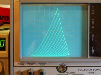
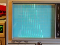
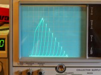
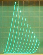
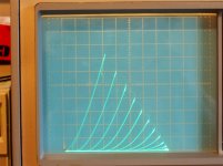
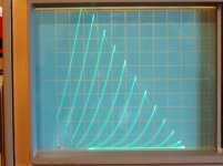
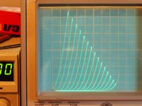
Here are some curves for another Vertical Sweep triode, the 6FJ7. (the 10 Watt section) This triode has a higher Mu (15.4) than the previous Vertical Sweep 13GF7 (Mu 5.4) (equiv. to 6EM7), so has more gain to use in the new Series Schade Fdbk scheme (CED, UnSet).
50V/div Horiz for all.
a) 6FJ7 native mode, 20 mA/div Vert.
b) 6FJ7 series Schade, 20 mA/div Vert.
c) 6FJ7 series Schade, 50 mA/div Vert.
The bent over curve sections at the top of the series Schade pic c) are from grid current I think. Notice the lack of curve roll-over for the Series Schade pics. And obviously lower Rp.
So the "oddball" Vertical Sweep 6FJ7 (with higher Mu) can perform quite well after all. I always thought it was sorta on the useless side. Fixed!
6BL7 is similar to 6FJ7.
Attachments
Last edited:
I have tried quite a few tubes in this setup, and just about anything can be made to work including some small signal remote cutoff pentodes. I have not tried to plot curves for many since I must do it manually.
The one tube I have not tried yet, and so far have not conquered, is one of the beam triodes intended for primary side high voltage regulator use in a TV set.
These have Mu around 300 and Gm over 60,000, and require positive grid voltage to even draw current on sane plate voltages (under 1000). They will oscillate if looked at funny, and I think that some may be quietly oscillating (laughing at me) while sitting on the shelf in their boxes.
Some type numbers: 6HV5, 6HS5, 6HZ5, 6JD5, and 6JH5. many of these come in two plate sizes depending on who made them, and when. Heater current doesn't always match the tube manual either, I have seen from 1.5 amps to 2.5 amps.
I believe that the 6JD5 was on the dollar list at one time because I have 10 identical tubes with the rubber band still around them from ESRC.
I'll get them wired into an UNSET board eventually, once I have tested the big box full of suspects waiting in line.
. . . . . I always thought it was sorta on the useless side. Fixed! . . . . . . . ..
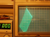
I always thought that the 'ideal triode' would have straight evenly spaced grid bias lines running at 45º from bottom left to top right. What's the best way to deal with near vertical curves? Low resistive load to maximize current swing or CCS for voltage? (Hmmm, I think I just answered my own question - I'll post it though 'cause you most certainly have more to say than I know.)
The vertical line type triode curves (or just plain lower Rp) are capable of driving lower impedance loads. Well, just plot a load line on them.
Two factors (for triodes) affecting distortion along the load line are the diode shape of each curve itself, leading to 2nd harmonic mainly, at too low a load Z.
And the other factor is the roll-over in the triode curves toward the HV end. This is caused by the grid 1 wires being too close to the cathode (relative to wire spacing) done in order to get higher gm. This proximity effect, or "island effect" makes the transfer function of grid 1 closer to square law (V to I) over the usual operating range, while the plate (or grid 2 for pentodes etc) is far enough away from the cathode and has a near 3/2 power law. The mis-match, 2 versus 3/2, causes the plate curve roll-over typically seen. The Schade type local N Fdbk removes much of this since the N Fdbk is across the offending g1 to cathode.
Your "ideal triode" with sloping equal spaced straight lines IS possible if the Schade N Fdbk is sent back via a Crazy Drive type grid setup. (Rg2g1 and Rg1k resistors) with a Mosfet follower (generally required) for grid 2 current. And using the "new" P-Mosfet cathode drive for signal input relative to g1 and g2.
Here is a pic of such a Crazy Fdbk triode setup, except not using the g2 Mosfet follower yet (hence very low V gain, since the low value Schade resistor has to carry g2 current here), hence the closely spaced curves in the pic. (I'll get around to a properly isolated g2 curve set soon, this was just a quick and dirty short-cut to demonstrate the "straight" curves proof of concept.)
Yeah, those beam triodes are going to need some plus grid 1 Volts, and some Mosfet followers to drive them. Hopefully something will work out there. If the two Mosfet voltage ratings can handle it.
Attachments
Would you say how you set up the 6FJ7 for that sweep?
My understanding of the UNSET is limited but as I've been working on a grounded grid power amp for the past few months I can't help seeing it as a sort of quasi grounded grid amplifier with only the feedback necessitating a resistor from grid to ground.
My understanding of the UNSET is limited but as I've been working on a grounded grid power amp for the past few months I can't help seeing it as a sort of quasi grounded grid amplifier with only the feedback necessitating a resistor from grid to ground.
George gave a general schematic here:
https://www.diyaudio.com/forums/tub...sing-mosfet-ultralinear-feed.html#post6267790
In this case, for the 6FJ7 triode, the g2 supply is gone, and the two resistors around the grid were done by a single 600K pot so it would provide adjustable tube gain. I have the grounded end of the pot connected to an adjustable -V power supply, since the tracer can drive the cathode negative (see below). But same modus operandi as George's schematic.
With the TEK 576 curve tracer here, the step output (usually for base or gate/grid control) can do up to an amp (the 576 tracer is originally for SS small and power devices, 220 Watt max). So I don't need to put the P Mosfet in at the cathode for tracing, I just connect the step output directly to the cathode. (it has an internal N Fdbk control loop to ensure the step output agrees with the requested setting, with 20 Amp 350V output transistors to ensure that! With adjustable current limiting of course.) The Tek 576 provides DC offset (bias) and gain/step size controls for the step output. (I modified it years ago for tube tracing, so it can do up to +/- 170V total step range) The TEK 576 is just amazing, needless to say.
Last edited:
Thanks! This is very useful. The grounded grid amp I mentioned is three stage and started out with the the two sections of a 6FJ7 directly coupled , driving an IT into the 211 cathode.
Over time I came to think the circuit might sound better with more linear input and driver stages so switched to a video pentode input driving a DHT (tried a few like 2a3, triode 307a)
The linearity helped but so also did the additional power from the DHT.
With your revelation though I'd like to go back to the 6FJ7 as if it works well would make for easy direct coupling within a single envelope and eliminate a DHT filament supply.
Not sure yet that the lower power wouldn't be missed though. . . . .
Thanks again !
Don't forget that the improved linearity with this scheme comes at the cost of less output gain from the triode. Some gain has to be used up for the N Fdbk. I used up about half the gain for the 6FJ7 curve plot.
I'll curve trace a 6LU8 next, a 14 Watt beam pentode and a 2.5 W Mu 58 triode on the same 12 pin base. The pentode provides plenty of gain for the N Fdbk and can still have good output gain. Needs a screen supply however.
By the way, a 12HL7 (curve tracer selected, triode connected) can provide a very linear Mu 24 triode. (pic)
Hmm..., I should trace the 12HL7 with series Schade (CED, UnSet) N Fdbk. Linearity should be from outer space.
Attachments
Last edited:
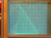
Here are some curves for the 21LU8 pentode.
All are 50 mA/div Vert., 50V/div Horiz., and 8 V steps
a) native triode mode
b) series Schade mode on pentode
c) reduced gain series Schade mode on pentode
d) native triode mode with series Schade mode added
Looks like the series Schade (CED, UnSet) on pentode mode have less of the "roll-over" issue
Attachments
Last edited:
So sad, really, for losing any member here!
Stan was never a member here, or even a serious computer user. I knew Stan from when his father, Irving ran the business in South Florida near where I worked. Both of them often attended a free flea market held in the parking lot of the Motorola plant by the ham radio club. Stan often called me to find out who was who on this forum when people called him saying that they heard about him here. Stan was not active in any audiophile activities and didn't attend any audio related shows. He did hit the major hamfests every year and hosted an antique radio show in his parking lot as often as once a quarter.
The ESRC name came from his father, the Electron Supply Replacement Corporation.
Btw, I always wonder how some get informed by such a tragedy?
I visited his shop last December and all appeared normal. I had not seen Stephanie in my last two trips to his shop, but I assumed it was due to her poor mobility. She was the computer person.
I had picked out a box full of several hundred tubes, but left them there since I was transporting a bunch of stuff for a family and friends Disney World trip. He was going to bring them to the Dayton Hamfest, which never happened because of Covid, and it now it appeared that he passed before the Dayton event day. I found out here:
ESRC Status?
Don't forget that the improved linearity with this scheme comes at the cost of less output gain from the triode.
Thanks for the warning, I won't forget.
I figured the 211 cathode input impedance to be something around 1KΩ and wanted to have around 7K on the plate of the 'FJ7 so used an an IT ratio of 2.6:1. So with the feedback a switch to IT with 1:1 ratio will probably make it about the same gain.
With the IT I'm using there's a sweet spot with around 55mA primary current no matter what the tube . I'm guessing it has something to do with balance between primary and secondary as they're both carrying DC . . . maybe part of the reason the 6FJ7 at 40mA never sounded quite right. So together with the feedback, changing to a different transformer might allow it to work well as driver.
BTW, it has the same triode sections as the 6DN7 which back in Sound Practices days I remember someone referring to as the poor man's 45.
I think 'maybe not', but still has been a useful tube, especially with sections direct coupled for an amp factor of 300. Plenty to give up for the feedback.
Thanks yet again Don !
Thanks re Stan. My audio biz partner Tom was a loyal customer; even received Christmas cards from Stan. Someone asked one time whether Tom or I had the most tubes (we were in the 'Shop' that we are leasing for storage; building and listening); we looked at each other and immediately decided to pass on that one...Tom would tend to buy 50 or 100 'tube of the week' that we had built into a Project; but I have been collecting longer.
I am a real Compactron fanatic. So for Spud Amps I favor 6FM7 or; for more power 6LU8. Want to really kick butt? 42KN6; which I just bought one for less than $15 shipping included. Doesn't hurt that Compactrons have been overlooked by the audio sheep and they are American. Europe did not make these (they favored Novar); there were some Japanese knockoffs (but very good quality). And the wonderful Chinese are manufacturing duodecar sockets.
- Home
- Amplifiers
- Tubes / Valves
- Those Magnificent Television Tubes