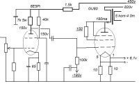
PP and SE
SE 30W, halfcathode
PP 1200W Ua=3500v
SE : http://www.lampovik.ru/Production/Tower/Tower.htm
SE 30W, halfcathode
PP 1200W Ua=3500v
SE : http://www.lampovik.ru/Production/Tower/Tower.htm
Attachments
Last edited:
Hi giorgos,
I was only (half) kidding before")
However, I have to say I must agree with Bandersnatch about the SE vs. PP choice. It's insane to build a SE amp using this tube, EVEN at low output power. The requirement causing the problem in the OPT is not power but it is the primary current. High DC current -> large air gap in core -> low primary inductance -> bad bandwidth ...
I would recommend PP but of course this brings it to 4 tubes for a stereo amp... Maybe that's too much overkill
Perhaps, given the low power level, parafeed-SE with a resistive anode load is a possibility?
Kenneth
I was only (half) kidding before
However, I have to say I must agree with Bandersnatch about the SE vs. PP choice. It's insane to build a SE amp using this tube, EVEN at low output power. The requirement causing the problem in the OPT is not power but it is the primary current. High DC current -> large air gap in core -> low primary inductance -> bad bandwidth ...
I would recommend PP but of course this brings it to 4 tubes for a stereo amp... Maybe that's too much overkill
Perhaps, given the low power level, parafeed-SE with a resistive anode load is a possibility?
Kenneth
No, no, no...that won't do at all. The g3 has both anode and socket connection and you do not want full plate voltage( both AC and DC ) on the socket for an amp like this.
cheers,
Douglas
It's insane to build a SE amp using this tube, EVEN at low output power. The requirement causing the problem in the OPT is not power but it is the primary current. High DC current -> large air gap in core -> low primary inductance -> bad bandwidth ...
Without reading all that is written here I still would like to suggest to study the possibility to make the SE version with hi-mu triode connection.
This is g1 + g2 connected together.
Then the standing current is essentially lower and the gain relatively high (>100).
But ofcourse this requires A2 operation, i.e. driving power.
I have used much smaller GU50 this way and the results were very promising.
The power output was 15 W with 800 V supply voltage and 45 mA idle current.
The OPT was 10 k.
Perhaps, given the low power level, parafeed-SE with a resistive anode load is a possibility?
perhaps ??????? can we do that way???
I would suggest a solution for OPT: take Hammond 1650R PP trans, make air gap, so you have SE with Imax = 380mA, and RL = 5k. Bat this is compromise solution
resistive anode load need to 1800 V Ua, and R 5k 400W
Last edited:
GU81m Fishbowl
The GU81m is one amazing outputpentode.
At the moment i have it running at 1300V/400mA at 5K-plateload.
The parafeedchoke is 2x11H (so 44H in series), EI180x125 (35kg).
The outputtransformer is 2x1K15 (so 5K in series), same size.
All transformers are home-made. Unable to buy them at a normal shop or internetsite.
The Parafeedcap is 6uf.
Response is about from 3Hz till end of meter. Slewrate is off-scale.
And for the price, you don`t have to worry about the lifetime.
The DC on the filaments must be perfect DC. Anny hum you will hear quite clear. I use 3-fase transformers with a very heavy stabilisator.
Since the tube is using an small current on the grid, i advice to use an interstagetransformer 2:1 or 3:1 to power the tube.
Any 18W-25W pentode can be used as driver. (i prefere to have some headspace)
This is my summertube by the way.
The TB3-2000 (500W output) and GU5b (1100W output) are producing too much heat for warm days. These are running at 1K25 plateload with an 10uf parafeedcap. All works great since the amp is fully modular.
PS. site will be updated soon.
GU81
Hi Fishbowl! Inspiring projects you do!
Would love to learn more about your GU81 experience.
How does it sound, esp. on bass?
How much power do you get? Do you use feedback?
The grid current you mention: when does it start to appear
and how heavy it is at 0V bias?
I'm thinking of a dedicated bass amp (200Hz max)
around it. Looking at the curves (if they are reliable??)
I've figured out 1500V/300mA
-85V loaded with 3.2k should give up to 190W.
For the driver I thought about triode-connected 6E5P, DC coupled, but no idea on how much power the grid would like to see at 0V???
THanks!!!
phixphi
Hi Fishbowl! Inspiring projects you do
!Would love to learn more about your GU81 experience.
How does it sound, esp. on bass?
How much power do you get? Do you use feedback?
The grid current you mention: when does it start to appear
and how heavy it is at 0V bias?
I'm thinking of a dedicated bass amp (200Hz max)
around it. Looking at the curves (if they are reliable??)
I've figured out 1500V/300mA
-85V loaded with 3.2k should give up to 190W.
For the driver I thought about triode-connected 6E5P, DC coupled, but no idea on how much power the grid would like to see at 0V???
THanks!!!
phixphi
Hey Guys, I have a working monoblock, push-pull, pure class A, based on a pair of two GU-81M (actually, GU-80 - very similar) tubes.
If anybody still interested, drop me a line.
Some preliminary photos / flims - can be found on my facebook page, as well as on my blog (hiend-audio.com)
Or on my Facebook:
https://www.facebook.com/zygmunt.jerzynski/photos_all
Cheers,
Ziggy.
If anybody still interested, drop me a line.
Some preliminary photos / flims - can be found on my facebook page, as well as on my blog (hiend-audio.com)
Or on my Facebook:
https://www.facebook.com/zygmunt.jerzynski/photos_all
Cheers,
Ziggy.
Last edited:
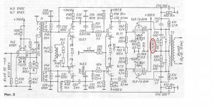
This might help...a triode curve for GU-81m monster tube
ÃÓ80 < ÃÓ < Àëôàâèò < Ëàìïû < Óñèëåíèå < ÁàçàÏðàêòèêè < AudioDB : Áàçà Çíàíèé Audio
ÃÓ80 < ÃÓ < Àëôàâèò < Ëàìïû < Óñèëåíèå < ÁàçàÏðàêòèêè < AudioDB : Áàçà Çíàíèé Audio
Hello ,
in "Linear Audio" Vol. 8 you can see a project with GU81 :
volumes | Linear Audio
106 watts with a distortion of 0,023 % . It is a MTA ( Multiplied Transconduction Amp ) circuit from my friend Frank Bloehbaum .
First parts of the power supply :
Kind regards , Alexander .
in "Linear Audio" Vol. 8 you can see a project with GU81 :
volumes | Linear Audio
106 watts with a distortion of 0,023 % . It is a MTA ( Multiplied Transconduction Amp ) circuit from my friend Frank Bloehbaum .
First parts of the power supply
:An externally hosted image should be here but it was not working when we last tested it.
Kind regards , Alexander .
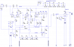
Just a quick sketch. Front end is a K2-X op-amp. But this is nothing more than the conditions from a previous post with the op-amp for accuracy. It could also be DC coupled with a cathode follower and taking the +/-300V op-amp supplies negative by 85V (or the cathode follower drop plus the proposed bias for the GU-81).
Attachments
You seem to have GU81 LTSpice model. Would you like to share that ?
I have a pair of GU-81M waiting for a project.
my version:
**** GU81 ******************************************
* Created on 03/27/2015 22:10 using paint_kit.jar 2.9
* Model Paint Tools: Trace Tube Parameters over Plate Curves, Interactively
* Plate Curves image file: gu81.jpg
* Data source link:
*----------------------------------------------------------------------------------
.SUBCKT TRIODE_GU81 1 2 3 ; Plate Grid Cathode
+ PARAMS: CCG=3P CGP=1.4P CCP=1.9P RGI=2000
+ MU=3.19 KG1=2130 KP=48 KVB=639 VCT=0.88 EX=1.4
* Vp_MAX=1300 Ip_MAX=1000 Vg_step=40 Vg_start=80 Vg_count=11
* Rp=2880 Vg_ac=273,6 P_max=450 Vg_qui=-232,8 Vp_qui=1000
* X_MIN=123 Y_MIN=63 X_SIZE=915 Y_SIZE=715 FSZ_X=1612 FSZ_Y=868 XYGrid=false
* showLoadLine=y showIp=y isDHT=n isPP=n isAsymPP=n showDissipLimit=y
* showIg1=n gridLevel2=n isInputSnapped=n
* XYProjections=n harmonicPlot=n harmonics=y
*----------------------------------------------------------------------------------
E1 7 0 VALUE={V(1,3)/KP*LOG(1+EXP(KP*(1/MU+(VCT+V(2,3))/SQRT(KVB+V(1,3)*V(1,3)))))}
RE1 7 0 1G ; TO AVOID FLOATING NODES
G1 1 3 VALUE={(PWR(V(7),EX)+PWRS(V(7),EX))/KG1}
RCP 1 3 1G ; TO AVOID FLOATING NODES
C1 2 3 {CCG} ; CATHODE-GRID
C2 2 1 {CGP} ; GRID=PLATE
C3 1 3 {CCP} ; CATHODE-PLATE
D3 5 3 DX ; POSITIVE GRID CURRENT
R1 2 5 {RGI} ; POSITIVE GRID CURRENT
.MODEL DX D(IS=1N RS=1 CJO=10PF TT=1N)
.ENDS
*$
- Home
- Amplifiers
- Tubes / Valves
- GU-81m tube amp schematics???