Here's how Rob Watts explains noise floor modulation which is not the same as Mallinson's as Terry pointed out.
Here he is pointing out that when RF noise intrudes it can create small ground plane currents in the analogue stage of a DAC which in turn causes a tiny amount of IM distortion & NFM therefore increases
Here he is pointing out that when RF noise intrudes it can create small ground plane currents in the analogue stage of a DAC which in turn causes a tiny amount of IM distortion & NFM therefore increases
‘Yes all sources create RF noise. We have two ways of coupling RF noise - via the cables, or electromagnetically. This mode is stopped with Dave being made from a solid block of aluminium - it is extremely well screened. The mains, and the outputs are RF filtered too. On the USB, we have galvanic isolation, but that will not completely isolate Dave from the source, as it has 2pF of coupling capacitance on the galvanic isolation (all isolators have some level of coupling capacitance).
Now this coupling capacitance is important, as RF noise voltages from the source will inject a small current into Dave's ground plane - and due to the ground plane having a 0.5 ohms per square and about 1 nH inductance per square will create small internal RF voltages that is picked up by the analogue electronics which will then induce a tiny amount of IM distortion, and so noise floor modulation will increase - even though Dave has immeasurably small amounts of RF noise modulation, the small extra amount is audible.
But if you run the source from batteries, and have no ground connected to the lap-top, then there are no net currents flowing into Dave, as the isolation capacitance of the lap top to ground is much smaller than the 2 pF from the isolators; in effect you are now completely isolating the source from Dave via the direct USB connection and so no RF currents from the source can be injected into Dave's ground plane. That's why this mode sounds a bit smoother and warmer than mains powering the lap-top.
Last edited:
(& doesn't show in the standard measurements)
Steady state noise vs level is a standard and easy to do measurement. The transient one not so much, but I don't know why there is not simply a noise floor impulse response.
Yes, I did state it that way which was incorrectYou seemed to talk of noise modulated before the signal came along, which can only happen in digital systems.
Sure but not showing up on a measurement usually means not present or are you saying that we have lots of measurements but that does not mean we are measuring everything that is present? I agree with this if that's what you mean!You may find it helpful to distinguish between 'showing up' and 'being present'.
Indeed, what you say makes perfect sense but only if you reduce everything down to only considering sine waves as the ONLY excitation signal that might create IMD & don't envisage any other possibility that might result in IMD.The nonlinearity which causes IMD is the same nonlinearity which causes harmonic distortion. The only difference is the frequency, which may in turn change how the distortion 'shows up'. If you put two sine waves A and B into a system with second-order distortion then you get A-B and A+B in the output. We call this IMD. If A and B are the same frequency then you still get A-B and A+B in the output, except now we call A-B a bias shift (which some people seem unaware of) and A+B we call the second harmonic. We call this harmonic distortion. Fundamentally nothing has changed.
Here's how Rob Watts explains noise floor modulation which is not the same as Mallinson's as Terry pointed out.
There is no inductance per square.
Calculator for the Inductance of a Flat Wire
The only way to avoid effect of coupling capacitance (2pF) and thus the fast edges is to use a piece of fiber optic cable. The same way as when we measure fast transients with less than 1us rise time on HV and VHV. I wonder mixed signal designers have not realized yet. Opto couplers are inefficient.
Dual tone or single tone or anything else - it is always the same non-linearity you are exploring. You just need to understand and interpret what you see and measure. In case of single sine tones you use more frequencies. 30kHz FS HD is a tough test.
Maybe some additional light from Bruno P to a similar question put to him here
Q: About correlation between sinewaves and music, we see more and more the 32 tones test (32 sines equally spaced on log scale from 20Hz to 20 kHz).
From an instinctive standpoint, it looks like being closer to a musical signal than 1 or 2 sines. Is the instinct not to be trusted in this case?
A:The more complex the test signal, the more likely you are to separate out the different nonlinearities that together make up amplifier distortion. On the other hand, it becomes harder to read the graphs. Once you use more than 2 sine waves the plots become quite hard to interpret. You have to do some calculations to work out what particular combination of tones underlies a particular spur.
............
In other words, you need to know something about the circuit you’re testing. For instance, in an optimally biased class AB amplifier the 19+20 kHz test would fail to expose thermal modulation of the bias point, so you’d need to do further testing with a signal that produces significant low-frequency power as well.
Anyone who claims to have found the ultimate test battery that will validate any piece of audio kit (and believe me, I’ve met a few who claimed that there was nothing to amplifiers but a few THD numbers) had better consider the Test Daemon.
We had some direct e-mail communication with BP regarding modulation and IM products in class D amps about a year ago.
Re your remark about those 2pF coupling noise, I have been specialized in measurements of very small fast signals in the environment with very high EM intereferences, one of the most severe conditions, hundreds of kV and units of MV dielectric breakdowns in SF6, surrounded by currents up to 100kA.
Re your remark about those 2pF coupling noise, I have been specialized in measurements of very small fast signals in the environment with very high EM intereferences, one of the most severe conditions, hundreds of kV and units of MV dielectric breakdowns in SF6, surrounded by currents up to 100kA.
Then you must have seen/understood what he is saying about sine wave testing?We had some direct e-mail communication with BP regarding modulation and IM products in class D amps about a year ago.
It wasn't my remark but I gathered you had used optical fiber on HV transient testing from your previous posts.Re your remark about those 2pF coupling noise, I have been specialized in measurements of very small fast signals in the environment with very high EM intereferences, one of the most severe conditions, hundreds of kV and units of MV dielectric breakdowns in SF6, surrounded by currents up to 100kA.
It doesn't get away from the fact that RF intrusion into devices can cause IM products but as DF96 states "Numbers would be good. How much RF? How much IM? How much noise floor modulation?"
If they aren't forthcoming just ask Richard and/or Mark for their opinions"Numbers would be good."
Hmmm. Good old SF6. Good HV dielectric. Makes for good HV, high current, fast switching for dumping HV charged C banks into load (for plasma accelerator).Re your remark about those 2pF coupling noise, I have been specialized in measurements of very small fast signals in the environment with very high EM intereferences, one of the most severe conditions, hundreds of kV and units of MV dielectric breakdowns in SF6, surrounded by currents up to 100kA.
Fond memories.
THx-RNMarsh
Well numbers, in a lot of cases, "In other words, you need to know something about the circuit you’re testing" & what is the best technique/best test signal to expose what is being searched forIf they aren't forthcoming just ask Richard and/or Mark for their opinions
"For instance, in an optimally biased class AB amplifier the 19+20 kHz test would fail to expose thermal modulation of the bias point, so you’d need to do further testing with a signal that produces significant low-frequency power as well."
That is what I'm trying to find - a better test to expose NFM with the idea of a multitone test signal that varies but perhaps this is the totally wrong direction?
Numbers can be had but they are unique to each specific product.If they aren't forthcoming just ask Richard and/or Mark for their opinions
-RNM
Last edited:
Because, as Scarface, Tony Montana said, "The time has come, we gotta expand."I don't quite understand, Joe has his Elsinore thread where he and his posse can ruminate to their hearts content.
More accurately, "in audiophile fantasy".There is of course another group who just want to collaborate with normal, well-adjusted people who are interested in audio.
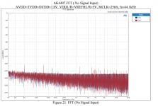
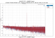
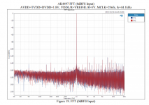
Scott, There are two definitions here. One is what M Mallinson was referring to WRT modulator state variable settling The second is what Rob Watts was referring to WRT the difference in noise floor of a DAC comparing a steady state 0dBFS signal to -60 dBFS (or lower) signal. The noise floor is modulating with signal amplitude. The latter is is easily seen in data sheets and what RW claims to be audible.
PS sorry if this is confusing the discussion, I know you guys are on a different track, just wanted to clarify.
T
See attached from AK4497 EVM datasheet. Looks like a serious problem...
I'm not sure why anyone takes Rob very seriously in terms of claims. He is marketing his product in that video. He mentions anecdotes like his kids heard changes watching cartoons. The old wife-in-the-kitchen thing.


You won't know until you try it, talk is cheap.That is what I'm trying to find - a better test to expose NFM with the idea of a multitone test signal that varies but perhaps this is the totally wrong direction?
Numbers can be had but they are unique to each specific product.
Not it's location?
You (and HvM) cannot have it both ways. Either your impedance compensation affects the output voltage of the amp+cable (in which case it is not a voltage source) or it does not (in which case it can have no effect).
But that is not what the topic is about. Why are you rephrasing it into something it is not? Simply you have not understood it, or maybe just couldn't be bothered. OK then.
Why not make sentences and paragraphs which have meaning, within the context of electronic engineering, rather than inventing your own language?
My language is just fine and understood by others. Reframing a topic is not the same thing as inventing a language. The language is the same.
But I do admit, this is a tough topic, that is why it intrigues myself and others so much. But there is an equation at the heart of this and it tricks up so many people because, in truth, it is constantly ignored: F=BLI - it has become an inconvenient truth.
Electric Drives - Electrical Machine Fundamentals - Description and Applications
(Edit: Please note at the very beginning of that article the bi-directional nature of motors - but if this topic does not interest, then OK.)
Last edited:
You continue to take any criticism of your ideas as a personal attack.
No, not at all. Now we are ramping this up to make me sound paranoid?
It was an attempt at humour, can't we lighten up?
Maybe Mark can comment...
I would love Mark to comment. We might actually get a fruitful discussion going.
... do you think this is true of the Benchmark amplifier or better yet do you think it would fail its distortion specs into an 8 Ohm load at 40 degrees of phase?
Excellent question. Can we discuss it? Mark?
BTW, what is distortion when taking into account this equation: F = BLI
The truth about that equation means we have to define just exactly what is distortion when we connect a voltage source to a current device? What do we end up listening to when connecting to dynamic loudspeakers (which are motors)? Is it the voltage of the amplifier OR is it the current of the amplifier?
Is this not a fair question to ask? What exactly are we listening to?
- Status
- Not open for further replies.
- Home
- Member Areas
- The Lounge
- John Curl's Blowtorch preamplifier part III