Most people where? Not here I don't think. Anyway, how does this set up work? It seems to me it's about balancing the sound pressure into each half of the room from each speaker?This is certainly lots different from what most people do, set the speakers whereever and just toe them straight at you and sit at the triangle point.
You haven't been paying attentionHint: it was your ears tuning into the ‘new’ sound.
")
Spider is impregnated cloth. Cone surround is rubber.
On larger 10”-12”drivers with impregnated cloth surround I have noticed a drop of Fr around 10% with a few days exercise but I haven’t made a follow up survey along time to see if Fr recovers.
George
The only explanation I can think is some kind of (work?) hardening of either surround or spider, but could impregnated cloth or rubber be subjected to that? Perhaps the rubber surround was actually made from santoprene, which can have excellent long term stability, but also may contain plasticisers. Which do not always have a lot of staying power. Dunno, remains interesting find.
In the end, it does not seem to matter much for loudspeaker alignment. Vas and Fs are on a seesaw. Take for example Keele's formula for an optimum BR enclosure: Vb=15(Q^2.87)Vas. When Fs goes down, Q also goes down, compensating at least to some extent for the increase in Vas.
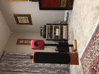
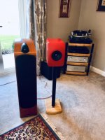
I did the North West Audio Show (Cranage Hall, Cheshire) in 2017 and we had a very small room - 3m x 3.5 or 4m IIRC. The 703’s did not work in the room (to be expected) but the LS50’s were fantastic. I used the bungs with the middle section removed and placed them about 1/2 a meter from the rear wall for some reinforcement and used a 100 watt amp. Quite a few people came back for a second listen and were very positive about the sound. Keep in mind the show had speakers ranging from half the price of the LS50’s all the way up to 20 grand horns, 22 grand B&W’s, big KEF Blades etc.
I played Bill Frisell (always fantastically recorded), George Benson, Manhattan Transfer (on vinyl) and some classical stuff.
I played Bill Frisell (always fantastically recorded), George Benson, Manhattan Transfer (on vinyl) and some classical stuff.
Last edited:
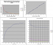
Hi Dimitri, thanks again for the measurements of the Levinson JC-2.
It is interesting that you showed the deviation in the RIAA from ideal.
I would like to explain the history of this:
Back in 1973, when the JC-2 was designed, I had a Heathkit IM analyzer and a Heathkit sine-sq generator as my reference test equipment. I did pretty well on those two, like speaker measurements, lowering the self noise of our B&K mikes by 10dB, achieving 0.4nV/rt Hz with my patented JC-1 design, etc, BUT it was not optimum for an ACCURATE RIAA. The deviation from 0dB on the Heathkit meter alone was probably 0.5dB or more over a 10dB range with level. It was just a vacuum tube based circuit and no more was expected of it.
Also, there were no PRECISE measurements easily available of what the absolute dB correction should be, just time constants of 75us, etc. No, Walt Jung, nor Dr. Lipshitz had published their RIAA passive pre-correction circuit then and would not for another 7 years. So, I used what esteemed engineer Richard Burwen did for the RIAA correction of Mark's existing LNP-2 phono stage. I just copied his caps and resistors. After, Burwen must have known what he was doing. '-) Well, he didn't, and when I confronted him about it a few years later, he said that he liked the sound of that EQ and that was good enough for him. Today, of course, with precision passive pre-correction circuits and better test equipment, we can do +/- 0.1dB over the whole frequency range with precision caps and resistors. But back then, almost nobody did it perfectly, unless by accident. The first guy to do it right was Tom Holman, I believe.
Best way to test an RIAA IMV is with an inverse filter fed from a square wave. I got the idea after reading a Baxandall article on it. He just mentioned how it worked and I tried it. Turns out it’s amazingly sensitive to response anomalies.
An Accurate Inverse RIAA Network
Of course now you can do it with a sound card, but where’s the fun in that?
Haven’t seen that - very nice write up as always from Rod Elliot.
(How’s the Bernstein/Gershwin CD BTW?)
I don't know what to say
Be Joyful. It may not be exactly the speakers he wanted, but when someone is happy with their purchase and the purchase is affordable fidelity (for given value of affordable) all is good with the world.
I don't think, Bonsai, because I've not listened a lot during the first two days: may-be 3 tunes ? Too disagreeable.Hint: it was your ears tuning into the ‘new’ sound.
I have the habit to change speakers from studio to studios, and never changed my mind with "habit": too dangerous ;-)
I thought they were "broken-in", because I bought them used. So I had email the seller and his answer was it has not used-them more than few hours because he had a better system in //.
No, very little, my triangle is 2m50. ;-(I also suspect if your listening space is big, the LS50’s will be s bit lost.
Last edited:
In the end, it does not seem to matter much for loudspeaker alignment. Vas and Fs are on a seesaw. Take for example Keele's formula for an optimum BR enclosure: Vb=15(Q^2.87)Vas. When Fs goes down, Q also goes down, compensating at least to some extent for the increase in Vas.
I agree Vacu.
Burn-in time does not seem to matter much for loudspeaker alignment.
But as T-S parameters vary with test signal level a lot, one has to be careful as to the level of test signal.
It should be at the “small signal” range but not too weak (IMO close to the level that produces 1/4 Xmax cone excursion)
George
Attachments
What you may not know is that a bunch of amps in the Store use (regulated) 24V SMPS with filtering, and lots more use (unregulated) 24V linear supplies feeding constant current loads (Class A amplifiers) and thus the supply voltage itself varies not much at all.
Nevertheless, good luck eliminating supply dependence. Node "BBB" in the 3 transistor circuit is a temperature dependent percentage of the power supply (it's a voltage divider after all). To eliminate supply dependence you would need to down-regulate to a constant voltage and then arrange your voltage divider (or Wheatstone bridge) to output a temperature dependent percentage of that constant. Don't forget, at the end, you must apply that percentage to the fan itself, i.e., (supply independent X%) times (unregulated VCC volts). Without an analog multiplier of course.
It is possible (everything is possible!) and it has been done, but the implementations I've seen all work in percent-of-supply terms from input to output, i.e., they assume that supply variations are much much slower than the bandwidth of the fan control system's feedback loop.
You might want to use the MAXIM chip inside a little mu metal box, feeding an analog control voltage output to an analog output buffer-driver that's outside the box. Build a one stage or two stage voltage regulator (3.3V!) inside the box and assure yourself that the fan voltage is a well regulated, well controlled, X volts independent of supply. Uh, that is, when the fan voltage is low. When the fan voltage X volts is high, and the varying supply means that supply < X occasionally, well, you are screwed. Maybe a cautious person runs a 12V fan from a "24V" unregulated supply, with an emitter follower fan driver. Now you can tolerate more than 33% variation on your unregulated supply with no impact upon the fan control system. And of course, double the total power dissipation.
edit- Stripboard trace cutter is, conventionally, a 5/32" drill bit twisted with fingers only, at a slow speed. The drill chews away all of the copper and only a small amount of the phenolic circuit board material. Clean-up with a continuity buzz tester, a headband magnifier, and an X-acto knife.
Mark,
This is not a competition! I am I think way cheaper than you.
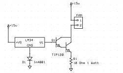
First is what I used from a 15 volt supply to a 12-14 volt fan. As I knew all the parameters a very simple design.
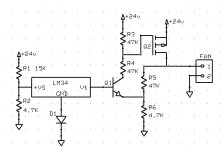
Second is the same idea modified to run on 24 volts and minimize the voltage drop as you did.
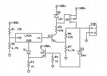
Third adds a regulator to limit the fan to 24 volts.
I think the secret is the LM34 temperature sensor. It produces .01V per degree F. It has a maximum input voltage of 35 volts and draws 90 uA. (It also seems to have gone way up in price since I laid in my supply of them! I paid under a $1.)
ES
Attachments
Last edited:
Mark,
This is not a competition! I am just I think way cheaper than you.
First is what I used from a 15 volt supply to a 12-14 volt fan. As I knew all the parameters a very simple design.
Second is the same idea modified to run on 24 volts and minimize the voltage drop as you did. I added a gate protection diode although at 24 volts a resistor would still do.
Third adds a regulator to limit the fan to 24 volts.
I think the secret is the LM34 temperature sensor. It produces .01V per degree F. It has a maximum input voltage of 35 volts and draws 90 uA. (It also seems to have gone way up in price since I laid in my supply of them! I paid under a $1.)
ES
In a related subject, I was contracted to provide a thermal stabilizing circuit with interesting constraints: it had to hold the temperature of a heatsink within +/- 1°F, had to be non-contact and had to drive a fan. Since the temperature of the air leaving a heatsink is time-delayed from the temperature of the device mounted to it, using the air temperature as the sensing element can result in a sawtooth thermal variation or very slow response to ambient changes. I ended up using a ZTP-135 optical IR thermopile as a sensing element looking at the device on the heatsink driving a PWM fan controller chip from Microchip. Once the tracking was tweaked the circuit worked well, but is too elaborate and expensive for consumer devices, as I found out trying to adapt it for ham radio use.
Howie
This is not a competition! I am I think way cheaper than you
The nontrivial bits:
LM34/35 temp sensor IC costs $2.05 qty=1 for the cheapest model link 1
Vishay thermistor costs $0.61 qty=1 link 2
Cheapest medium power transistor (fan driver) in stock costs $0.41 qty=1 link 3
My chosen PMOS (fan driver) costs $1.12 qty=1 link 4
ES $2.05 + $0.41 = $2.46
MJ $0.61 + $1.12 = $1.73
Mark,
I guess when I run out of LM34s I will have to use the LM334 and two resistors. The LM334 LM334Z/NOPB Texas Instruments | Mouser is $.87
In a related subject, I was contracted to provide a thermal stabilizing circuit with interesting constraints: it had to hold the temperature of a heatsink within +/- 1°F, had to be non-contact and had to drive a fan. Since the temperature of the air leaving a heatsink is time-delayed from the temperature of the device mounted to it, using the air temperature as the sensing element can result in a sawtooth thermal variation or very slow response to ambient changes. I ended up using a ZTP-135 optical IR thermopile as a sensing element looking at the device on the heatsink driving a PWM fan controller chip from Microchip. Once the tracking was tweaked the circuit worked well, but is too elaborate and expensive for consumer devices, as I found out trying to adapt it for ham radio use.
Howie
Has anyone come across a replacement for the now defunct TI TMP006 thermopile chip? I have a project where ZTP-135 is just too big.
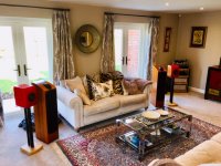
I hide this unsightly material in one of the castle's jails, to prevent the Castafiore from asking me to play her his recordings.How big is your room though - 2.5m x 2.5m and you live in a Château?
And if she finds out and asks me one day, I can lock her up.
Nb: Did I have to buy an aerosol of red paint?
- Status
- Not open for further replies.
- Home
- Member Areas
- The Lounge
- John Curl's Blowtorch preamplifier part III