Speaking of The New Generation, she's at least as soulful (!) as Bill Withers:
YouTube
I wanted to suggest that you start this video, close the window and just listen, but one of The Big Secrets here is already given away right there in the Youtube title. I saw this in a tweet in February - math professor and popular math book author (there's a contradiction there somewhere) Steven Strogatz tweeted congratulations to his daughter that after four years, one of her videos finally had a million views. Looks like it's going to close in on two million views soon.
I already know better than to ask you lol.That's easy just ask.
Dan.
It appears to be a puzzle to be solved by the reader. 🙂Ah Mark,
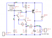
Looking at the schematic, where do you put the fan?
Also I call the card "Perf Board."
By a short analysis (and no, I didn't cheat by using LTSpice), I've determined that the fan goes between ground and the line labeled "FANPLUS," or across resistor R7.
And of course the solution to "getting rid of the heat" brings up the problem of "getting rid of the fan noise." My first thought is a PC isolation box, but that's surely not as pretty as the device being cooled. The second thought is a "fake" amplifier that's the same (or looks the same) as the real one, but only the volume and power controls are wired up, connecting to the "real" amplifier in a closet somewhere.
Hi Dimitri, thanks again for the measurements of the Levinson JC-2.
It is interesting that you showed the deviation in the RIAA from ideal.
I would like to explain the history of this:
Back in 1973, when the JC-2 was designed, I had a Heathkit IM analyzer and a Heathkit sine-sq generator as my reference test equipment. I did pretty well on those two, like speaker measurements, lowering the self noise of our B&K mikes by 10dB, achieving 0.4nV/rt Hz with my patented JC-1 design, etc, BUT it was not optimum for an ACCURATE RIAA. The deviation from 0dB on the Heathkit meter alone was probably 0.5dB or more over a 10dB range with level. It was just a vacuum tube based circuit and no more was expected of it.
Also, there were no PRECISE measurements easily available of what the absolute dB correction should be, just time constants of 75us, etc. No, Walt Jung, nor Dr. Lipshitz had published their RIAA passive pre-correction circuit then and would not for another 7 years. So, I used what esteemed engineer Richard Burwen did for the RIAA correction of Mark's existing LNP-2 phono stage. I just copied his caps and resistors. After, Burwen must have known what he was doing. '-) Well, he didn't, and when I confronted him about it a few years later, he said that he liked the sound of that EQ and that was good enough for him. Today, of course, with precision passive pre-correction circuits and better test equipment, we can do +/- 0.1dB over the whole frequency range with precision caps and resistors. But back then, almost nobody did it perfectly, unless by accident. The first guy to do it right was Tom Holman, I believe.
I have some wonderful Ella Fitzgerald vinyls (from the Norman Grantz Great American Songbook series) and the brass, bass, drums and piano sound wonderful on the LS50's.
You were right, folks.
After 3 days+night of continuous music playing (with the door closed ;-), I made an other listening attempt this night.
It is day and night.
It is suddenly like an lens put in focus.
If the sound is thinner and still oriented high treble, I have gain a lot of substance everywhere. And I can afford the voices and the drums (appart cymbals, still too bright and still a little too light for my taste, "hifi").
The separation between the instruments are now not so far from my big system.
I will keep them, and, if I am in the middle of the break-in way, be totally satisfied:
80% of the horrible hardness and haze has yet disappeared.
Never seen an enclosure changing as much with break-in. Is it because the amps were new in the same time ?
A little problem: I wanted a little system full of indulgence and it seems they are even less tolerant to mixing faults than my big ones. If I still worked today, I would take them to watch my back.
Surprising little speakers.
if I am in the middle of the break-in way, be totally satisfied: 80% of the
horrible hardness and haze has yet disappeared. Never seen an enclosure
changing as much with break-in. Is it because the amps were new in the
same time ?
I believe this is the drivers breaking in. The passive version does the same.
Another week or two should help further.
It appears to be a puzzle to be solved by the reader. 🙂
By a short analysis (and no, I didn't cheat by using LTSpice), I've determined that the fan goes between ground and the line labeled "FANPLUS," or across resistor R7.
And of course the solution to "getting rid of the heat" brings up the problem of "getting rid of the fan noise." My first thought is a PC isolation box, but that's surely not as pretty as the device being cooled. The second thought is a "fake" amplifier that's the same (or looks the same) as the real one, but only the volume and power controls are wired up, connecting to the "real" amplifier in a closet somewhere.
Yes that is right. I was teasing Mark as he left off the terminals. He mentioned the smoothing capacitor but was not quite explicit in the fan connection or Zener diode power dissipation. With a slight modification the circuit would not be rail voltage dependent.
Looking at the schematic, where do you put the fan? ... ... Also I call the card "Perf Board."
Hi Ed, as member benb has remarked, the fan is the load which the Pchannel MOSFET drives. It connects between the drain of the MOSFET driver, and the opposite supply. As benb said.
The schematic I attached, was from LTSPICE. I think it creates prettier schematics than the alternative. But LTSPICE does not have "connectors" as primitive elements. The schematic I actually used to make the board, because it inter-operates with VeeCad, was from TinyCAD. The TinyCAD schematic is attached below. It is not as pretty. But it DOES show the connector for the fan, and the two other connectors as well. (These are visible as green blobs of plastic in the photograph). Member benb was right.
Stripboard (wikipedia entry) has a grid of holes with parallel stripes of copper which span the length of the board; each stripe is one row wide. It is the stripes of copper which make it useful, in my opinion. Perf Board, in my experience, does not have board-spanning long stripes of copper. It has either no copper at all, or else it merely has freestanding individual donuts around each hole, where no two holes are spanned by copper.
BTW the Zener part number explicitly given in the post, is 1N5929B which is 15V & 3W ... more than good enough for any of the little whizzers I bought off Mouser. In fact it's more than good enough for ANY of the 24V fans sold at Mouser for less than $20. (All the sub $20 fans are less than 4 watts i.e. 167 mA). Want more? Redesign!
_
Attachments
Last edited:
Mark,
I didn't see the copper busses. Vero board is different that way. Never heard the wiki name. Do you have a Vero board trace cutter or just use a knife.
I do take things like showing the fan connection seriously, particularly if you look at many of the posts here. Also have a dislike of circuits with a strong dependence on all parameters. A 24 volt unregulated rail is subject to AC power line whimsy. It can range from the equivalent of 110 volts or even less to an actual 135 volts RMS. (110 equivalent from flattened voltage peaks due to diode supplies loading.)
I need to look around to find the way I did it when I had the fan control issue. I recall using one of the solid state temperature sensors. (LM35 family.)
My day's effort was correcting the design of a microphone.
Last edited:
Thanks for the tip, rayma. Without your advice, I would have given up.I believe this is the drivers breaking in. The passive version does the same.
Another week or two should help further.
I don't know what is inside, but I will try, if it is possible and if I find some courage, to compensate the impedance curve of the drivers by a passive network. The only way i know to soften and densify the sounds without loosing attacks and micro dynamic.
(No ferrites in my stock of coils, Max, don't worry, only fresh air ;-)
One thing is pretty strange, while I have the feeling that basses are now present in the room, from outside, door closed: mainly high medium goes out.
Not the case with my big system.
Also have a dislike of circuits with a strong dependence on all parameters. A 24 volt unregulated rail is subject to AC power line whimsy.
What you may not know is that a bunch of amps in the Store use (regulated) 24V SMPS with filtering, and lots more use (unregulated) 24V linear supplies feeding constant current loads (Class A amplifiers) and thus the supply voltage itself varies not much at all.
Nevertheless, good luck eliminating supply dependence. Node "BBB" in the 3 transistor circuit is a temperature dependent percentage of the power supply (it's a voltage divider after all). To eliminate supply dependence you would need to down-regulate to a constant voltage and then arrange your voltage divider (or Wheatstone bridge) to output a temperature dependent percentage of that constant. Don't forget, at the end, you must apply that percentage to the fan itself, i.e., (supply independent X%) times (unregulated VCC volts). Without an analog multiplier of course.
It is possible (everything is possible!) and it has been done, but the implementations I've seen all work in percent-of-supply terms from input to output, i.e., they assume that supply variations are much much slower than the bandwidth of the fan control system's feedback loop.
You might want to use the MAXIM chip inside a little mu metal box, feeding an analog control voltage output to an analog output buffer-driver that's outside the box. Build a one stage or two stage voltage regulator (3.3V!) inside the box and assure yourself that the fan voltage is a well regulated, well controlled, X volts independent of supply. Uh, that is, when the fan voltage is low. When the fan voltage X volts is high, and the varying supply means that supply < X occasionally, well, you are screwed. Maybe a cautious person runs a 12V fan from a "24V" unregulated supply, with an emitter follower fan driver. Now you can tolerate more than 33% variation on your unregulated supply with no impact upon the fan control system. And of course, double the total power dissipation.
edit- Stripboard trace cutter is, conventionally, a 5/32" drill bit twisted with fingers only, at a slow speed. The drill chews away all of the copper and only a small amount of the phenolic circuit board material. Clean-up with a continuity buzz tester, a headband magnifier, and an X-acto knife.
Last edited:
Not as easy as comparing painting with photo of that painting but it can be done by listening. That would be the job of the one who records and masters the replayable music. As for the replaying job of hi-fi electronic equipment to convert digital signal to analog signal, amplify and convert it to sound waves would be to make output at high level of faithfulness to input.Side by side painting/photo image comparisons should easy, but how can you compare recorded music with unprocessed live music?
Amazon - LS50 - Pic is this what you have ?.Thanks for the tip, rayma. Without your advice, I would have given up.
I don't know what is inside, but I will try, if it is possible and if I find some courage, to compensate the impedance curve of the drivers by a passive network. The only way i know to soften and densify the sounds without loosing attacks and micro dynamic.
(No ferrites in my stock of coils, Max, don't worry, only fresh air ;-)
One thing is pretty strange, while I have the feeling that basses are now present in the room, from outside, door closed: mainly high medium goes out.
Not the case with my big system.
My reference to ferrite is Class D amp output filtering, not crossover coils, but you knew that 😉.
Zobels ought to help ime with Class D.
I would not expect a 5" bass driver to shake the walls....the sub is needed !.
- Connect wirelessly via dual-band Wi-Fi connectivity or Bluetooth 4.0, as well as wired via an asynchronous USB Connection, digital (TOSLINK) input, or an RCA analog input.
- The LS50W uses a 5.25" Uni-Q driver capable of reaching down to 40Hz, combined with a built-in 192Khz/24bit DAC and 230W amplifier.
- Wirelessly control the LS50W with the accompanying iOS or Android app. Wi-Fi Network Standard : IEEE 802.11a/b/g/n. Wi-Fi Network Frequency Band : Dual-band 2.4GHz/ 5 GHz
- If you're after additional bass, the LS50W can output to a connected subwoofer. Output to the connected subwoofer is controlled by the LS50W app. Frequency Response : (plus/minus 3dB) Measured at 85dB/1m
- Choose from Titanium Gray/Red, Gloss Black/Blue, or Gloss White/Copper for your LS50W.
Have fun tweaking them.
Dan.

I bought them used and aged of 14 month. So I supposed they were "broken-in".
I don't know what to say 🙂You were right, folks.
After 3 days+night of continuous music playing (with the door closed ;-), I made an other listening attempt this night.
It is day and night.
It is suddenly like an lens put in focus.
If the sound is thinner and still oriented high treble, I have gain a lot of substance everywhere. And I can afford the voices and the drums (appart cymbals, still too bright and still a little too light for my taste, "hifi").
The separation between the instruments are now not so far from my big system.
I will keep them, and, if I am in the middle of the break-in way, be totally satisfied:
80% of the horrible hardness and haze has yet disappeared.
Never seen an enclosure changing as much with break-in. Is it because the amps were new in the same time ?
A little problem: I wanted a little system full of indulgence and it seems they are even less tolerant to mixing faults than my big ones. If I still worked today, I would take them to watch my back.
Surprising little speakers.
That's easy just ask.
Did you explain to him that your taste in music is ‘industrial thrash metal’?
Haha, I'm well aware lol, hence my reply...Did you explain to him that your taste in music is ‘industrial thrash metal’?
I already know better than to ask you lol.
Dan.
You were right, folks.
After 3 days+night of continuous music playing (with the door closed ;-), I made an other listening attempt this night.
It is day and night.
It is suddenly like an lens put in focus.
If the sound is thinner and still oriented high treble, I have gain a lot of substance everywhere. And I can afford the voices and the drums (appart cymbals, still too bright and still a little too light for my taste, "hifi").
The separation between the instruments are now not so far from my big system.
I will keep them, and, if I am in the middle of the break-in way, be totally satisfied:
80% of the horrible hardness and haze has yet disappeared.
Never seen an enclosure changing as much with break-in. Is it because the amps were new in the same time ?
A little problem: I wanted a little system full of indulgence and it seems they are even less tolerant to mixing faults than my big ones. If I still worked today, I would take them to watch my back.
Surprising little speakers.
Hint: it was your ears tuning into the ‘new’ sound.
This why you can go to a show where they play an £250 000 pair of ‘Vox Olympian’ horns and they sound ‘horny’: hollowed out and nothing like real life. Some shake their heads in disbelief while other also shake their heads in a different kind of disbelief.
I have a pair of B&W 703’s and a pair of Q320’s (these cost me about £180).
The 703’s are sonorous, lively and exciting and the bass goes deep. The LS50’s are accurate and on jazz and vocals they excel. On the 320’s I can listen to classical music and the sound is quite acceptable. Put some pop or rock music on and straight away you can tell they re not right and especially in the mid- range.
I also suspect if your listening space is big, the LS50’s will be s bit lost.
- Status
- Not open for further replies.
- Home
- Member Areas
- The Lounge
- John Curl's Blowtorch preamplifier part III