Harmonic distortion probably in the AP. I sometimes get noise at 2.7 k. Don't know where it comes from. I think the skill in looking at any measurement is the feel for what is real or not.
Try a set of headphones on the AP jack and select analyzer residual as the source. You can quite often hear what you can't see. You are trying to look at Nano Volt levels in a world full off many Micro Volts. I often hear voices from radio stations (I hope).
You mean this one 900hp Quant EV powered by flow cell batteryLast I looked the claim was distortion inversely proportional to current and the load was still noted with a question mark! This is the kind of stuff the water powered cars folks do.

No, the batteries where you replace just the electrolyte have been around a while. The water power is literally the water or sometimes an "unknown" state of the hydrogen atom. The creative dance some of these folks do in Youtube videos with a bunch of cheap meters is amusing.
No, the batteries where you replace just the electrolyte have been around a while. The water power is literally the water or sometimes an "unknown" state of the hydrogen atom. The creative dance some of these folks do in Youtube videos with a bunch of cheap meters is amusing.
Some experimental cars even run on compressed air.
Thanks for that paper.
You are welcome.
If we still can't model it without getting wormy deviations from the measured result, then I doubt we understand it enough to rule out nonlinearity based on the very math that's failed to model it without anomalies.
We (they
) understand it enough (introduce eddy currents in the picture).Are the models used in that paper compromised to provide computational expediance, or do they represent the best effort at modeling skin effect?
There has to be an exact model against which the other –less computation intensive- models were compared.
If you like, look for details in parts 1,2,3
G3YNH info: Components and Materials.
Rest parts only confirm that RF guys are some levels higher than Hi-End audio guys, plus only technical talk, no BS (no pun intended
)George
Last edited:
Try a set of headphones on the AP jack and select analyzer residual as the source. You can quite often hear what you can't see. You are trying to look at Nano Volt levels in a world full off many Micro Volts. I often hear voices from radio stations (I hope).
Thanks
skin effect paper addresses numerical problems, not math, modeling limits
Linear Systems, the required math to show Linearity is very well established
the "Classical" equations of EM in Linear media meet the requirements for Linearity
"Classical" meaning pre-Quantum, up to the approximation of continuously divisible charge - but charge is discrete so we do get a zoo of effects - many which can only be seen at cryogenic temps - when air is liquid or even solid - not so helpful in Audio
http://www2.physics.ox.ac.uk/sites/default/files/BandMT_11.pdf I don't get a lot from this - over my head - but it does show anisotropic magnetoresistance in Cu - at 4.2K, of course in loudspeaker voice coils the Cu may occasionally reach 400K
also looks like audiophile cable people could step up their Quantum buzz words
The exact calculation of the internal impedance of a solid cylindrical conductor or 'round wire' involves Bessel functions of the first kind, of zero order, with complex arguments (and derivatives thereof).
This type of problem can be separated into real and imaginary parts using the Kelvin Bessel functions, Ber, Bei, Ber' and Bei'.
The Kelvin functions are computed from infinite series expansions of alternating sign, and higher terms involve large powers of the argument divided by large factorials; small increments to the returned value being obtained by subtraction of one very large number from another.
This, unfortunately, is the kind of procedure that falls foul of the range limitations inherent in standard computer arithmetic.
Linear Systems, the required math to show Linearity is very well established
the "Classical" equations of EM in Linear media meet the requirements for Linearity
"Classical" meaning pre-Quantum, up to the approximation of continuously divisible charge - but charge is discrete so we do get a zoo of effects - many which can only be seen at cryogenic temps - when air is liquid or even solid - not so helpful in Audio
http://www2.physics.ox.ac.uk/sites/default/files/BandMT_11.pdf I don't get a lot from this - over my head - but it does show anisotropic magnetoresistance in Cu - at 4.2K, of course in loudspeaker voice coils the Cu may occasionally reach 400K
also looks like audiophile cable people could step up their Quantum buzz words
compensated semimetals (equal number of holes and electrons at Fermi surface) such as Bi
Last edited:
Random time dither does not make harmonic distortion. In fact wiggle either axis (amplitude/time) randomly and you get randomly phased noise sidebands another thing not shown in your plot. The magnitude only FFT losses the phase information.
I think Simon thinks time variant, not phase noises. Not that it makes any sense here...
Linear Systems, the required math to show Linearity is very well established
the "Classical" equations of EM in Linear media meet the requirements for Linearity
We all agree on linear systems.
Try calculating the Lorentz force on a wire loop under sinusoidal excitation. edit: this is the force that tries to open the loop..
Place two air core inductors next to each other, power them in series such that they magnetically attract. What is the equation for the magnetic force?
A small variant: what is the acoustic output of an electrodynamic speaker where the magnetizing current is not DC, but sine?
jn
Last edited:
gee, I'm pretty sure I mentioned the forces between wires many months ago - that is one of what I would call "multiphysics" effects - if the wires don't move it has no consequence for circuit analysis
and we have the known result of ordinary construction twisted pairs carrying audio signal don't spoil our measurement with 2nd harmonic at -120 levels
I have personally made -160 dB noise floor 2nd order IMD nonlinearity tests with null result after replacing AVX brand NPO with polystyrene caps in a 40 kHz Sallen-Key lowpass
another "multiphysics" effect is tempco and self heating
maybe you should pot your coils in polystyrene?
and spell out in small words exactly what your talking about, where the nonlinearity arises, I think DF and I have been very clear on specifically talking Classical EM which we believe is a fantastically good approximation in good metallic conductors at room temp home audio wiring current density...
Last edited:
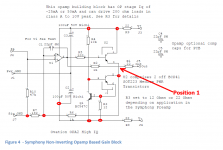
I think Figure 4 really needs a solder-dot in Position 1. I've noted a few other places where solder-dots might be nice to have, but IMHO it's mandatory for Position 1.
Attachments
I think Simon thinks time variant, not phase noises. Not that it makes any sense here...
Time/phase at some point equivalent, I wonder if we have crossed the KBK threshold and are due for some more Canadian poetry.
I know your point I was just being a little snarky showing a real product . Given the large amount of lab research done in the world an "unknown" state of hydrogen atom did not get misted by the germans or USA in WWII sorry .No, the batteries where you replace just the electrolyte have been around a while. The water power is literally the water or sometimes an "unknown" state of the hydrogen atom. The creative dance some of these folks do in Youtube videos with a bunch of cheap meters is amusing.

Well Scott I'll make you you happy I may have an error in my AP test, as I got different results on today's run with a slightly different approach. I left the abused cable in place with a load resistor and then ran an FFT, then not moving anything clipped the load resistor's lead. I did not get the same results as before. Much less change.
So skin effect SHUNTS inductance? Does this mean that if I maximize skin effect, I am actually reducing inductance? This means that in a wire, impedance vs F starts with 0 phase, then goes to 90 phase, then 45 phase with skin effect onset. IE skin effect only occurs while DC resistance is swamped by inductance.
Furthermore, would current crowding cause a change in inductance? Could nonlinear distortion here be attributed to a modulation in inductance? What are the phase of the harmonics relative to the fundamental? In a ground plane current density affects inductance, why not in a wire?
Also, what proportion of the skin resistance is nonlinear? It can't be completely nonlinear if it can be modeled well with linear components. So for instance what would be the THD of the wire current from a voltage source, how would it vary depending on frequency and signal level?
To get your answer, you need to take a look at the way physics explains things --- fields. If you know the density of the field varies and where that density changes in, say, a conductor or strip-line etc, you will konw where the impedance (L) is greatest and where it is lowest.
For example, in a round wire geometery .... looking into the end of the wire, the flux density is greatest in the center and less towards the outside. Where the flux density is greatest, the L is highest.And, since the flux density is lowest away from the center, the L is also lower away from the center.
Using a different geometry... on a pcb - a flat conductor over a ground plane or a strip-line: The most dense flux field lines are directly between the two conductors... except at the edge of the strip-line conductor where fringing affects reduce the density.... thus, the pcb edge has lower inductance... this is where the higher freqs will tend to travel.
THx-RNMarsh
Last edited:
Multiphysics? That's a new word on me.. Unless you think Asimov.gee, I'm pretty sure I mentioned the forces between wires many months ago - that is one of what I would call "multiphysics" effects
- if the wires don't move it has no consequence for circuit analysis
Mentioning the forces on the wire was used to demonstrate the conceptual math, it was not to explain any movement caused distortion.
The electrodynamic speaker was another example, perhaps more intuitive for everybody here, which shows a consequence of the physical structure. A voice coil within a magnetic field will have a force exerted on it proportional to the product of the field and the current in the coil. If the magnetic field is varied as a sine, and the voice coil current is the same sine, the force will be proportional to sine squared. If one now examines the resultant force vs time, to quote a wise sage...."toto, I don't think we're in kansas anymore".
The resistance of a wire in a coil undergoing proximity based modulation is just a wee bit more difficult to comprehend, but only because the resistance modulation is occurring as a result of the absolute value of the slew rate, or abs(derivative), of the exitation current. It rears it's ugly head whenever high fast changing fields and currents are desired, like in SMPS transformers.
I've left this in for continuity of post, although it is not part of my discussion..
and we have the known result of ordinary construction twisted pairs carrying audio signal don't spoil our measurement with 2nd harmonic at -120 levels
I have personally made -160 dB noise floor 2nd order IMD nonlinearity tests with null result after replacing AVX brand NPO with polystyrene caps in a 40 kHz Sallen-Key lowpass
another "multiphysics" effect is tempco and self heating
Polystyrene is not capable of the forces I have to contend with, anywhere from 1kpsi to 10kpsi for the simple stuff, 60kpsi and up once we exceed 20 tesla.maybe you should pot your coils in polystyrene?
He is actually ignoring the elephant in the room, and diverting to "everything is linear", despite actual examples to the contrary. The best example for most being the electrodynamic speaker example. Everything within an electrodynamic speaker is linear (small signal), yet how can it produce an acoustic output which is sine squared given a sine input?? (note, sine(x)^2 =1/2 minus 1/2 cos(2x), 2x is double freqency)and spell out in small words exactly what your talking about, where the nonlinearity arises, (I did) I think DF and I have been very clear on specifically talking Classical EM which we believe is a fantastically good approximation in good metallic conductors at room temp home audio wiring current density...
jn
Everything within an electrodynamic speaker is linear (small signal), yet how can it produce an acoustic output which is sine squared given a sine input?
I think you meant, "Everything electrical within an electrodynamic speaker is linear..." since the mechanical portion is largely responsible for the second order distortion in the limit of low displacement.
I think you meant, "Everything electrical within an electrodynamic speaker is linear..." since the mechanical portion is largely responsible for the second order distortion in the limit of low displacement.
Nitpickers, you and Steve Eddy, the bane of my existence...
But the mechanical portion is not responsible for the sine squared force caused by dual excitation of coil and field by the same sine.
jn
- Status
- Not open for further replies.
- Home
- Member Areas
- The Lounge
- John Curl's Blowtorch preamplifier part II